UTC Fire and Security Americas 773A-SMOKE Wireless Smoke Detector User Manual L66 esl
UTC Fire & Security Americas Corporation, Inc. Wireless Smoke Detector L66 esl
user manual

Installation Instructions
1
ESL Smoke Sensor Model 562
P
re
li
m
i
nary
Product Summary
The ESL Smoke Sensor Model 562 (smoke alarm) is a
Learn Mode, wireless, photoelectric smoke sensor with a
self-contained alarm siren, a low-battery annunciator, and a
status light. The smoke alarm is part of a security/fire
alarm system and communicates with the system control
panel.
Each smoke alarm uses two 3-volt lithium batteries. The
batteries are shipped with the unit.
Installation Guidelines
❑This equipment should be installed in accordance with
the National Fire Protection Association’s Standard 72
(National Fire Protection Association, Batterymarch
Park, Quincy, MA 02269).
❑Avoid installing the unit until all construction is com-
pleted. The mounting ring may be pre-installed.
CAUTION
Not compatible with CareTaker
Plus
and custom
versions with software versions 3.0 or earlier.
Not compatible with Commander 2000 and custom
versions with software versions 4.0 or earlier.
Equipment Needed
❑Phillips screwdriver.
❑Pocket-sized slotted screwdriver.
Programming
This section describes the basic steps for adding the sensor
to panel memory. For more detailed programming
information, refer to the specific panel installation
instructions.
Figure 1.Mounting Bracket.
To add the smoke alarm to panel memory:
1. Remove smoke unit from mounting bracket.
2. Put the panel in Program Mode/Learn Sensors.
3. Select a sensor group and sensor number.
4. Remove mounting bracket.
5. Press and hold the test button.
6. The panel will indicate that the sensor has been
learned.
7. Exit from program mode.
Note
Reinstall smoke unit on mounting bracket.
Mounting Guidelines
Determine the best mounting location for the smoke alarm
using the following guidelines:
❑NFPA 72, Chapter 2, Section 2-2.1.1.1 states as fol-
lows: “Smoke alarms shall be installed outside of each
separate sleeping area in the immediate vicinity of the
bedrooms and on each additional story of the family
living unit, including basements and excluding crawl
spaces and unfinished attics. In new construction, a
smoke alarm also shall be installed in each sleeping
room.”
❑NFPA 72, Appendix A, Section A-2.5.2.1 states as fol-
lows: “Smoke Detection - Are More Smoke Alarms
Desirable? The required number of smoke alarms
might not provide reliable early warning protection for
those areas separated by a door from the areas of the
house protected by the required smoke alarms. For this
reason, it is recommended that the household consider
the use of additional smoke alarms for those areas of
increased protection. The additional areas include the
basement, bedrooms, dining room, furnace room, util-
Document Number: 466-xxxx Rev. A
PRELIMINARY
April 2000
ITI Part No. 60-848-95, 60-849-95
2ESL Smoke Sensor Model 562
Mounting Guidelines Preliminary
ity roo, and hallways not protected by the required
smoke alarms. The installation of smoke alarms in
kitchens, attics (finished or unfinished), or garages is
not normally recommended, as these locations occa-
sionally experence conditions that can result in
improper operation.”
The above NFPA standards are a minimum
requirement for smoke sensor installation. For better
protection, we also require the installation of a smoke
sensor inside every bedroom in existing construction.
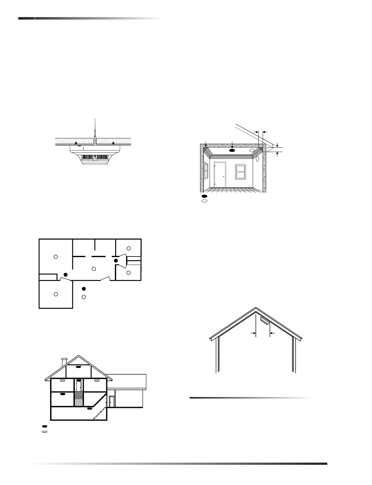
❑DO NOT mount a smoke alarm to a drop ceiling tile;
mount it to a metal runner (see figure 2).
Figure 2. Smoke alarm mounted to drop ceiling.
❑Mount all smoke alarms within 100 feet of the panel.
❑Install a minimum of two smoke alarms in any house-
hold, no matter how small it is.
❑Put a smoke alarm in the hallway outside of every bed-
room area. A minimum of two smoke alarms are
required in homes with two bedroom areas (see
figure 3).
A78-1171-02
Figure 3. Residence with multiple sleeping areas
❑Put a smoke alarm on every level of a multi-level resi-
dence (see figure 4).
Figure 4.Multi-level residence
❑Install basement alarms on the ceiling at the bottom of
the basement stairwell.
❑Install smoke alarms on the ceiling as close to the cen-
ter of the room as possible. If this is not practical,
install it on the ceiling no closer than 4 inches (10 cm)
from any wall or corner (see figure 5).
❑If ceiling mounting is not practical, install on an inside
wall between 4 and 6 inches (10 and 15 cm) from the
ceiling (see figure 5).
❑Put smoke alarms at both ends of a bedroom hallway if
the hallway is more than 30 feet (9 meters) long. Large
rooms over 900 square feet require more than a single
sensor.
Figure 5. Smoke alarm mounting locations
❑Areas with rough ceilings or short, transom-type walls
coming down from the ceiling require additional smoke
alarms.
❑Install second-floor smoke alarms on the ceiling at the
top of the first-to-second floor stairwell. Be sure no
door or other obstruction blocks the path of smoke to
the unit.
❑In rooms with sloped, peaked, or gabled ceilings,
install smoke alarms 3 feet (0.9 meter) measured down
on the slant from the highest point of the ceiling (see
figure 6).
Figure 6. Sloped, peaked, or gabled ceilings
Limitations
All alarms are subject to possible compromise or failure-to-
warn for a variety of reasons, for example:
❑Smoke alarms cannot detect smoke in chimneys, walls,
roofs, or smoke blocked by a closed door.
❑Alarms may not detect smoke on other levels of the
building.
BEDROOM
SMOKE DETECTORS FOR
MINIMUM PROTECTION
SMOKE DETECTORS FOR
MORE PROTECTION AND
REQUIRED IN NEW CONSTRUCTION
BEDROOM
BEDROOM
LIVING ROOM
DINING
ROOM
KITCHENFAMILY ROOM
BEDROOM
BEDROOM BEDROOM
LIVING
ROOM
KITCHEN
BASEMENT
GARAGE
SMOKE DETECTORS FOR MINIMUM PROTECTION
SMOKE DETECTORS FOR MORE PROTECTION AND
REQUIRED IN NEW CONSTRUCTION
BEST LOCATION
ACCEPTABLE LOCATION
DEAD AIR
SPACE BEST IN CENTER
OF CEILING
NO CLOSER THAN 4
"
(10 cm)
FROM SIDE WALL
MOUNT ON WALL
AT LEAST 4
"
(10 cm)
FROM CEILING
NO MORE
THAN 6
"
(15 cm)
FROM CEILING
HORIZONTAL
DISTANCE
FROM PEAK
3 FEET
(.9M)

3
ESL Smoke Sensor Model 562
Mounting
Preliminary
❑Alarms may not warn in time when fires are caused by
smoking in bed, explosions, improper storage of flam-
mables, overloaded electrical circuits, or other hazard-
ous conditions.
Do Not Install Smoke Alarms in the
Following Locations:
❑In or near areas where combustion particles are nor-
mally present such as kitchens; in garages where there
are particles of combustion in vehicle exhausts; near
furnaces, hot water heaters, or gas space heaters.
❑On the ceiling in rooms next to kitchens where there is
no transom between the kitchen and these rooms.
❑In damp or very humid areas, or next to bathrooms with
showers. Install sensors at least 5 feet (1.5 meters)
away from bathrooms.
❑In very cold or very hot areas.
❑In dusty, dirty, or insect-infested areas.
❑Near fresh air inlets or returns or excessively drafty
areas. Air conditioners, heaters, fans, and fresh air
intakes and returns can drive smoke away from smoke
alarms.
❑In dead air spaces at the top of a peaked ceiling or wall/
ceiling intersect. Dead air may prevent smoke from
reaching a smoke alarm.
❑Near fluorescent light fixtures. Install smoke alarms at
least 10 feet (3 meters) away from fluorescent light
fixtures.
Mounting
The mounting bracket must be separated from the unit
before you begin.
To mount the smoke alarm:
1. Secure the mounting bracket directly onto wood sur-
faces using No. 8, 1½ inch wood screws. If mounting
onto plaster or dry wall, use appropriate anchors.
2. Align the arrows on the mounting bracket with the
raised marks on the smoke alarm. Turn the smoke
alarm clockwise until it locks in place.
Testing
Test each smoke alarm every week to verify that its siren
and signal integrity are adequate. Refer to the specific panel
installation instructions for system response.
To test the smoke alarm:
1. Put the panel in sensor test mode. Although not neces-
sary for this model, it is a good practice to maintain.
Refer to the specific panel installation instructions for
details.
❑Simon and Advent panels must be in sensor test. If
not, you will not see anything at the panel.
WARNING
!
Commander and Caretaker panels will go into
alarm if not in sensor test when the test button is
pressed.
2. Press and hold the test button on the smoke alarm for 3
to 4 seconds.
Figure 7. Smoke Alarm Test Switch and Indicator Light.
The sensor should immediately transmit an alarm signal,
causing the siren inside the smoke alarm to sound and the
status light to flash rapidly. Refer to the panel’s installation
instructions for response details.
Note
After verifying that the siren and signal integrity are
adequate, you may want to cover the center opening
with your thumb. This will help reduce the siren noise
until the test is completed.
Maintaining the System
Replacing Batteries
When the batteries need to be replaced, the unit transmits a
signal to the panel. If the batteries are not replaced within 7
days, the unit will chirp every 40 seconds until the batteries
are exhausted.
Note
If you test the smoke alarm or it goes into alarm during
this 7-day period, chirp delay is canceled and the unit
begins chirping immediately.
Constant exposure to high or low temperatures or high
humidity may reduce battery life. Replace both batteries
when the smoke alarm or panel notifies you that the
batteries are low.
Note
For UL installations, use the following battery brands:
Sanyo CR123A, Panasonic CR123A, or Duracell
DL123A. These can be obtained through Interactive
Technologies, Inc. Do not mix brands.
Cleaning
Clean the smoke alarm chamber at least once each year.
Figure 8.Smoke Alarm diagram
To clean the smoke alarm chamber:
1. Place the panel in sensor test mode.
2. Remove smoke alarm from mounting ring.
3. Remove the batteries.
4. Separate housing from base.
5. Remove screen and chamber housing.
6. Vacuum screen, chamber housing, and chamber.
4ESL Smoke Sensor Model 562
Emergencies Preliminary
7. Reassemble smoke alarm.
8. Re-install the batteries.
9. Attach smoke alarm to mounting ring.
10. Test operation as describe in the “Testing” section.
Servicing
In the event that the smoke alarm needs servicing, send it to:
Interactive Technologies, Inc., 2266 Second St. North,
North St Paul, MN 55109.
Emergencies
Develop plans for a variety of emergency situations.
Periodically discuss and rehearse emergency plans that
includ the following:
❑Know the normal stat of doors and windows; open,
closed, or locked.
❑Use a different escape rout if closed doors feel hot to
the touch.
❑Emphasize that everyone should escape as quickly as
possible. Do not stop to gather any belongings.
❑Crawl and hold your breath as much as possible to help
reduce smoke inhalation during your escape.
❑Meet at a designated outdoor location.
❑Emphasize that no one should return to the premises if
there is a fire.
❑Notify fire department from a neighbor’s phone.
WARNING
!If you arrive at the premises and hear sirens, do
not attemp to enter the building. Call for emer-
gency assistance from a neighbor’s phone.
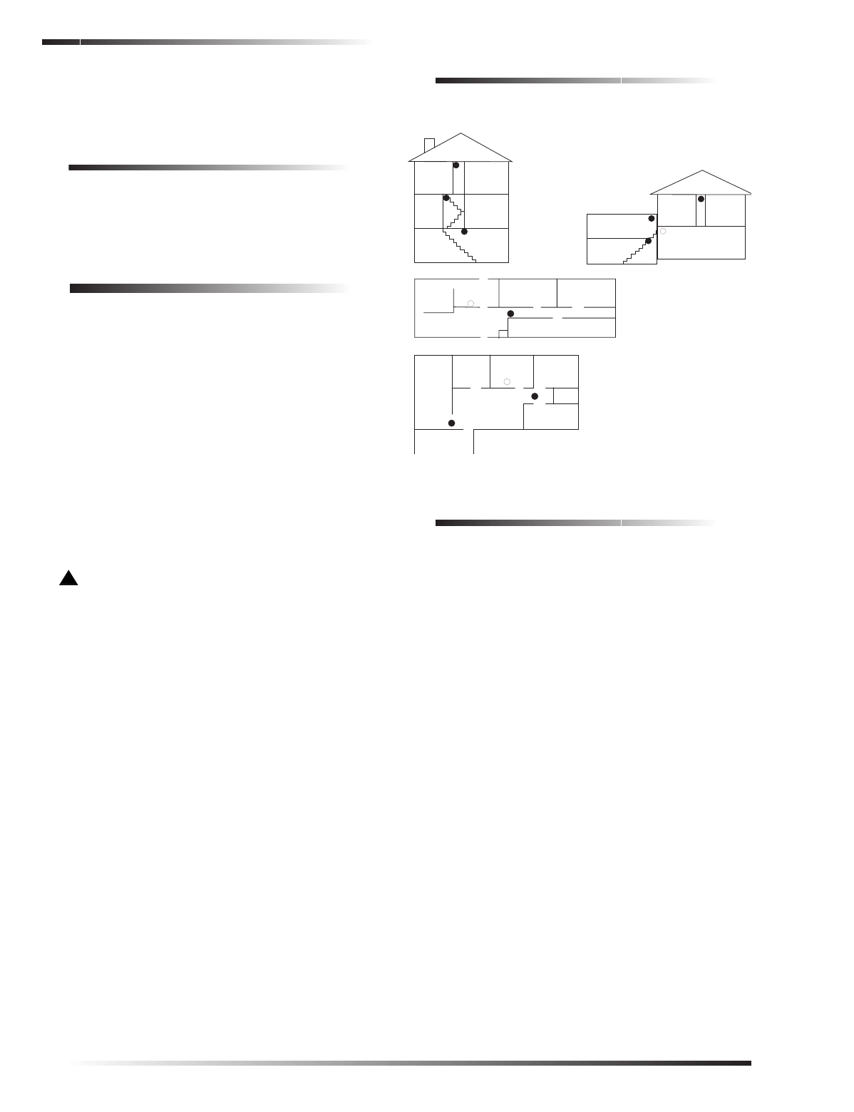
Floor Plan Example
Figure 9 is an example of a multilevel floor plan. Use it as a
guide and draw your floor plan on the next page.
Figure 9. Example of a floor plan.
Your Floor Plan
When establishing your excape routes, consider the
following guidelines:
❑Show all building levels.
❑Show all exits, (two exits per room are recommended).
❑Show the location of all components of the fire system.
❑Show the locations of any fire extinguishers, hoses,
ladders, etc.
Living
Room
Dining
Room
Basement
x
H
Hall
Bedroom Bedroom
Living
Room Recreation
Room
Basement
Hall
Bedroom Bedroom
Living
Room
Dining
Room
Hall
Bedroom Bedroom
Bedroom
Kitchen
A smoke detector should
be located on each level.
Smoke detectors should
be located between the
sleeping area and the rest
of the family living unit.
Living
Room
Bedroom
Bedroom
Bedroom
Dining
Room Kitchen
TV
Room
In family living units with more
than one sleeping area, locate a
smoke detector at each area.
H

5
ESL Smoke Sensor Model 562
Emergencies
Preliminary

6ESL Smoke Sensor Model 562
Specifications Preliminary
Specifications
Compatibility: Advent, Commander 2000 and
Custom Versions with software
versions 4.1 and later UltraGard, and
Custom Versions, Concord, Concord
Express, Simon
Dimensions: 2.25 × 5.0″ (without mounting
bracket)
2.25 × 5.5″ (with mounting bracket)
Temperature Range: 32° to 100°F
Humidity: 70% non-condensing
Power Source: Two 3-volt lithium batteries of the
same type. UL-approved types:
Sanyo CR123A, Panasonic
CR123A, Duracell DL123A.
Notices
Agency Listings: UL 217 (60-848-95)—Residential Installations
UL 268 (60-849-95)—Commercial Installations
This device complies with part 15 of the FCC rules. Operation is
subject to the following two conditions:
This device may not cause harmful interference.
This device must accept any interference received, including
interference that may cause undesired operation.
Changes or modifications not expressly approved by Interactive
Technologies, Inc. can void the user’s authority to operate the
equipment.
FCC Registration No.: B4Z-773A-SMOKE
651-777-2690
651-779-4890
ITI, Advent, CareTaker, Commander, UltraGard, and Simon are
registered trademarks of Interactive Technologies, Inc. Concord,
Concord Express, and Learn Mode are trademarks of ITI.