UTC Fire and Security Americas 779A-PIR Wireless Passive Infrared Motion Detector User Manual L661812a
UTC Fire & Security Americas Corporation, Inc. Wireless Passive Infrared Motion Detector L661812a
Contents
- 1. Users Manual
- 2. User Manual
Users Manual
1
ITI® Aritech APW 450 PIR Motion Sensor
ITI Part No. 60-XXX
Installation Instructions
Document Number: 466-1812 Rev. A PRELIMINARY
April 2000
P
re
li
m
i
nary
4/18/00
Product Summary
A motion sensor (passive-infrared or PIR) detects move-
ment within a specific area by sensing the infrared energy
emitted from a body as it moves across the sensor’s field of
view, causing a temperature change in the sensor’s zones.
When this motion is detected, the sensor transmits an alarm
signal to the control panel.
Use this motion sensor to protect locations where door/win-
dow sensors are impractical or not needed. For example,
use a motion sensor to protect large areas or open floor
plans. Motion sensors also provide backup protection for
door/window sensors.
The ITI® PIR utilizes advanced signal processing, a new
custom designed lens, and a new custom designed sensing
element. The combination of these improvements provides
false alarm immunity for pets with a combined weight of up
to 40 pounds while still providing superior human catch
performance.
This wireless motion sensor includes the following features:
❑35 feet by 40 feet coverage area
❑Three minute transmitter lockout time after an alarm
that helps extend battery life
❑Cover-activated tamper (optional wall-activated tamper
is included)
❑Supervisory signal transmitted every 64 minutes to the
control panel
❑Sensor low battery reports (trouble) to the control panel
❑Field-selectable sensitivity options (standard setting
required for pet applications)
Installation Guidelines
This PIR was designed for use in the presence of pets hav-
ing a combined weight of up to 40 pounds. The following
installation guidelines must be met to provide this false
alarm immunity.
1. If possible, locate sensors within 100 feet of the panel.
While a transmitter may have a range of 500 feet or
more out in the open, the environment at the installa-
tion site can have a significant effect on transmitter
range. Sometimes a change in sensor location can help
overcome adverse wireless conditions.
2. The required mounting height is 7 1/2 feet.
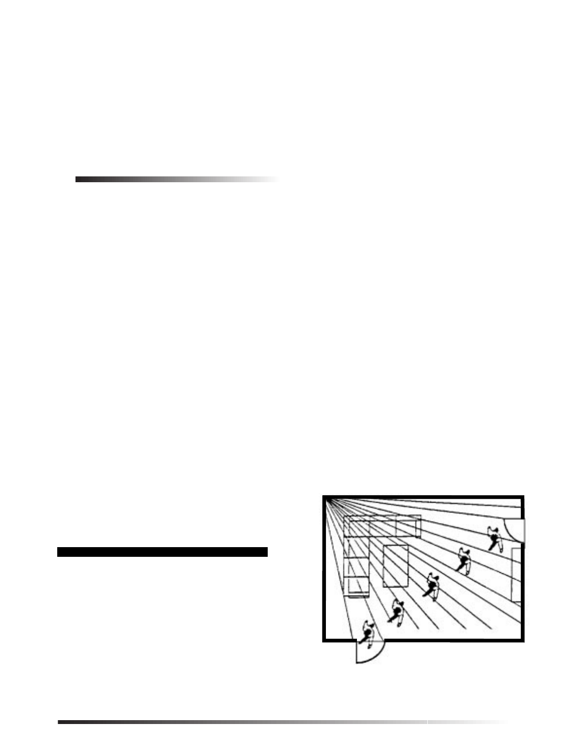
3. Position the sensor to protect an area where an intruder
would be most likely to walk across the detection pat-
tern (see Figure 1).
4. Mount the motion sensor on an insulated, outside wall
facing in.
5. Mount the motion sensor on a rigid surface which is
free from vibrations.
6. Position the sensor so it faces a solid reference point,
like a wall.
7. Do not aim the sensor at windows, fireplaces, air condi-
tioners, area heaters, forced air heating vents, or place
it in direct sunlight.
8. Do not mount the sensor near duct work or other large
metallic surfaces which may affect the RF signals (see
“Final Testing” on page 4). Actual acceptable transmit-
ter range should be verified for each installation.
9. Mount the sensor permanently on a flat wall or in a cor-
ner. Do not set it on a shelf.
10. Windows should be closed in any area which has an
armed motion sensor.
11. The pet must not be allowed to climb on objects such as
furniture, boxes, etc. within the field of coverage. See
Figures 2 and 3 to determine the sensor’s field of cov-
erage.
12. Room temperature must be kept at 60º F or higher.
13. The sensitivity switch must be set to Standard.
Figure 1.Overhead (Bird’s Eye View) Detection Path
8362G04B.DS4
Person walking across detection path
2ITI® Aritech APW 450 PIR Motion Sensor
Product Summary Preliminary 4/18/00
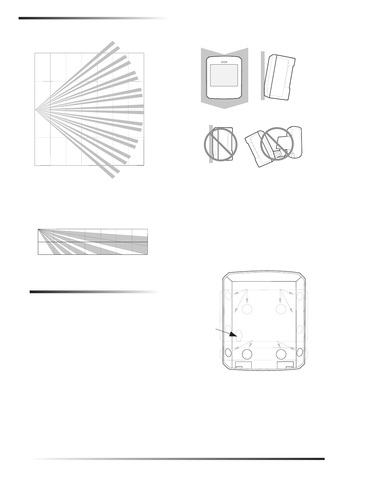
Figure 2.This graph shows the top view of the lens cov-
erage area, for the indoor motion sensor’s
lens.
Figure 3.Side view (Motion Sensor) at a mounting
height of 7.5 feet.
Mounting the Motion Sensor
This sensor must be incline-mounted on a wall surface or
incline mounted in a corner at a mounting height of 7.5 feet.
Figure 4.Wall mount options
To mount the sensor:
1. Remove the mounting plate by depressing the button
on the top of the sensor body. With the opposite hand
pull the mounting plate away from the body of the sen-
sor.
2. Punch out two of the bottom four mounting holes. See
Figure 4 for wall mount options. Use the lower-side
holes for corner mounting, or the lower-middle holes
for surface mounting.
3. If you desire wall-tamper functionality, remove the
wall-tamper knockout.
Figure 5.PIR Mounting plate knockouts
Note
The wall-tamper switch cannot be used when the sen-
sor is corner mounted.
4. Mark the location of the required holes on the mount-
ing surface.
5. Use wall anchors and screws to secure into place.
Attach the sensor to the mounting plate.
8362G11A.DS4
0 ft
20 ft
20 ft
0 ft
10 ft
2
0 ft
0 m 11 m
TOP VIEW
6 m
3 m
0 m
3 m
6 m
35 ft
7.5 ft
0 m
4 ft
0 ft 35 ft
11 ft
2.4 m
1.2 m
0 m
0 ft
DO NOT FLUSH MOUNT
INCLINED MOUNTCORNER MOUNT
DO NOT MOUNT
USING SWIVEL MOUNT
USE WITH
STANDARD LENS
U S E W IT H
ANIM AL ALLEY LEN S
8855G01A.DS
F
WALL
TAMPER
KNOCKOUT
USE THESE
MOUNTING
HOLES
DO NOT
USE THESE
MOUNTING
HOLES

3
ITI® Aritech APW 450 PIR Motion Sensor
Programming
Preliminary 4/18/00
6. When testing is completed the PIR can be securely
attached to its mounting plate by screwing the smallest
enclosed screw into the hole at the top of the mounting
plate.
Setting the Sensitivity on the Indoor
Motion Sensor
For pet applications, the PIR must be set to standard sensi-
tivity.
Walk Testing the Motion Sensor
Walk testing should be done to determine the sensor’s
actual coverage area. The edge of the coverage pattern is
determined by the first flash of the LED. This may change
slightly depending upon the sensitivity setting. Walk test
the unit from both directions to determine the pattern
boundaries.
1. Remove the sensor body from the mounted mounting
plate, activate the tamper switch, and then remount the
body to activate the 60 second walk test mode.
2. Walk across the coverage pattern to determine the cov-
erage area, indicated by LED activation. Each activa-
tion extends the walk test mode for an additional 60
seconds.
After 60 seconds without motion the walk test mode and the
LED will no longer activate when motion is detected.
CAUTION
Excessive use of the walk test mode may reduce
battery life. Use only for initial setup and maintenance
testing.
Note
When the walk test mode has ended, an alarm can be
transmitted only after 3 minutes have passed since
the previous alarm. This 3 minute lockout time
reduces unnecessary RF transmissions in high traffic
areas thereby extending battery life.
Environment Testing
Turn on all heating or air conditioning sources which would
normally be active during the protection period. Stand
away from the sensor and outside the coverage pattern and
watch for alarms.
Programming
Refer to the panel installation manual for information on
programming the sensor into the panel.
To trip the sensor:
1. Remove the back cover to activate the tamper switch.
2. Exit the panel’s programming mode.
3. Return the PIR to its mounting plate.
Maintenance
At least once a year, the range and coverage should be veri-
fied for proper operation. The end user should be instructed
to put the sensor in walk test mode and walk through the far
end of the coverage pattern to verify proper detection.
Replacing Batteries
When battery replacement is necessary, observe proper
polarity (as shown in the battery compartment) when
installing the new battery, or the sensor may be damaged.
Be sure to note that as you look at the battery compartment,
on the left side the positive side is down and on the right
side the positive end is up. When the battery is replaced,
wait at least 3 minutes after installing the battery before
activating the walk test mode.
Final Testing
Final testing should be done to verify radio signal integrity
and confirm control panel programming and response. The
actual transmitter range can be determined by performing a
sensor test as follows:
1. After the sensor has been mounted, remove it from its
mounting plate and activate the tamper switch to start
the walk test mode.
2. Replace the sensor in its mounting plate
3. Place the control panel in test mode. Move across the
detection pattern until the sensor’s LED turns on.
STOP your motion.
4. Listen for the appropriate system response. If the sys-
tem does not respond, proceed to Troubleshooting sec-
tion.
Troubleshooting
Use the following guidelines if the system does not respond
correctly when the sensor is activated.
❑Check programming and re-program sensor into panel
if necessary.
❑Move the sensor to another location and test for correct
response.
To relocate a sensor:
1. Test the sensor a few inches from the original position.
2. Increase the distance from the original position and
retest until an acceptable location is found.
3. Mount the sensor in the new location.
4. If no location is acceptable, test the sensor as follows:
❑Test a known good sensor at the same location.

4ITI® Aritech APW 450 PIR Motion Sensor
Specifications Preliminary 4/18/00
❑If the system does not respond, avoid mounting a
sensor at that location.
❑If the replacement sensor functions, return the prob-
lem sensor for repair or replacement.
Specifications
Power source: One 3-volt lithium
(CR123A) battery
Typical battery life: 2-4 years at 68° F
(not verified by UL)
Temperature range: 32° to 120° F
(Non-pet applications)
60° to 120° (Pet applications)
Notices
These devices comply with part 15 of the FCC rules. Opera-
tion is subject to the following two conditions:
❑These devices may not cause harmful interference.
❑These devices must accept any interference received,
including interference that may cause undesired opera-
tion.
Changes or modifications not expressly approved by Inter-
active Technologies, Inc. can void the users’ authority to
operate the equipment.
FCC ID: B4Z-779A-PIR
Patent No: 4,855,713
651-777-2690
651-779-4890
ITI is a registered trademark of Interactive Technologies, Inc