UTC Fire and Security Americas 779EPIR Wireless Outdoor Motion Detector User Manual Page 1 USA
UTC Fire & Security Americas Corporation, Inc. Wireless Outdoor Motion Detector Page 1 USA
UserManual.wiki
>
UTC Fire and Security Americas
>
779EPIR User Manual
user manual
Navigation menu
Upload a User Manual
Namespaces
Wiki Guide
HTML
PDF
Info
Views
User Manual
Discussion / Help
Navigation
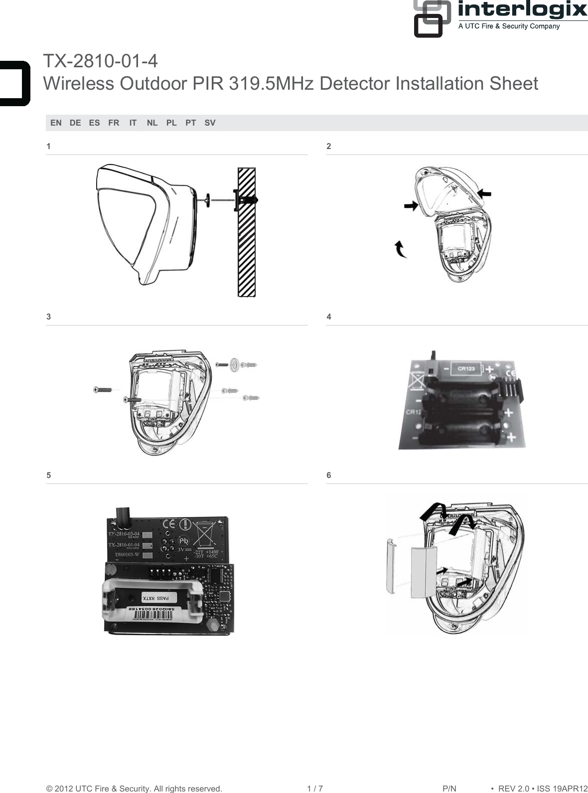
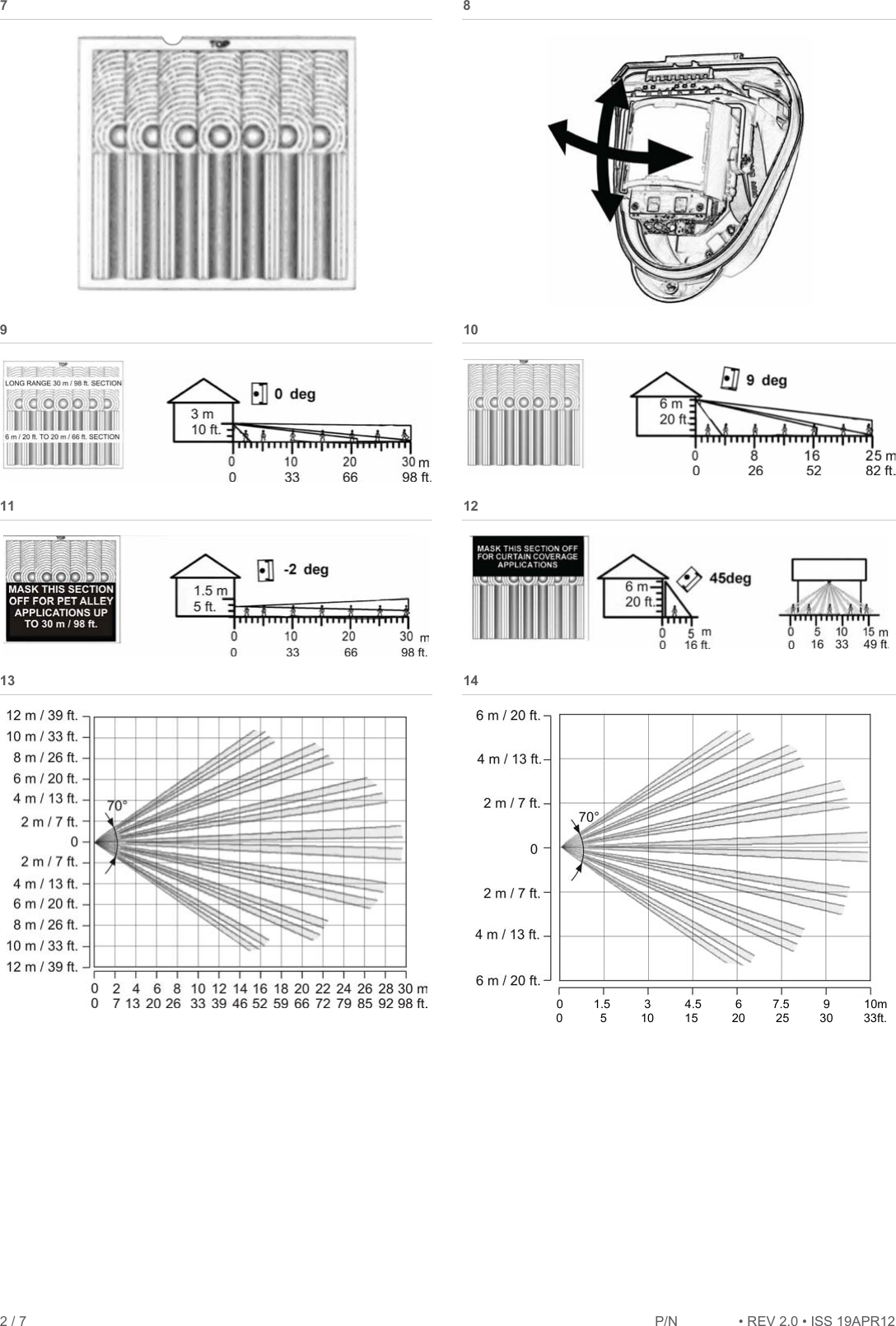
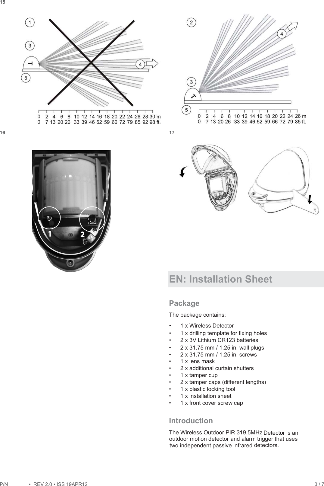
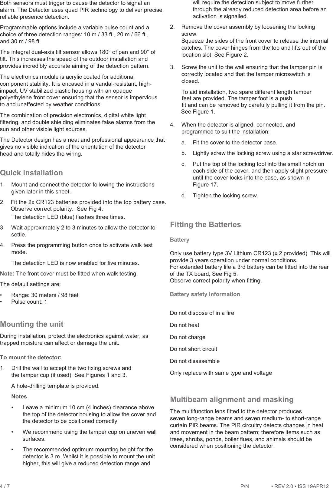
![P/1REV 2.ISS 19APR12 5 / 7 Note: PIR sensor is more sensitive to a movement across the beams, and less sensitive to a movement directly towards or away from the beams. The detector module is fitted with two sliding shutters to reduce the detection angle. The curtains are fitted to the pan and tilt module as shown in Figure 6. Each section of the detector lens gives a coverage pattern of approximately 10 degrees. An additional set of curtain sliders is provided should the beam pattern be narrowed even further, e.g. if the minimum detection angle of 10 degrees is required. When coverage exceeds the desired detection area, adjust the module as required and mask off any beams, either vertically or horizontally, to avoid unwanted detection. Use portions of the self-adhesive silver mask applied to the rear, smooth side of the lens as shown in Figures 11 and 12. Gently lift the top and bottom edges of the pan and tilt module to release the lens. To replace the module, please begin by sliding one side of the lens into the clips on the pan and tilt module. After one side is secure, do the same for the opposite side. Once both sides are secure, gently lift the top and bottom edges of the pan and tilt module and press on the lens to click it into place. Always replace the lens the correct way up to ensure exact beam pattern coverage. The top of the lens has a notch and is marked TOP as shown in Figure 7. Table 2 below summarizes typical masking configurations for use when the range option is set to 30 meters. Table 2: Masking configurations for maximum range Configuration Height (m / ft.) Tilt (°) Max. range (m / ft.) ReferenceMultibeam, optimum 3 / 10 0 30 / 98 Figure 9 Multibeam 6 / 20 9 25 / 82 Figure 10 Pet immunity [1] 1.5 / 5 í2 30 / 98 Figure 11 Curtain coverage [2] 6 / 20 45 5 / 16 Figure 12 [1] Black area should be masked for pet alley applications up to 30 meters / 98 feet. [2] Black area should be masked for curtain coverage applications. Figure 13 shows the pattern for the maximum range in the optimum position (see Figure 9). Masking the top section of the lens reduces the range to 20 m / 66 ft. Figure 14 shows the pattern for the minimum range (10 m / 33 ft.) In this case masking the top section of the lens reduces the range to 6 meters. Figure 15 shows possible alignments when the detector is mounted close to a wall. Figure 15 legend Item Description 1. 90° mounting, not recommended 2. 55° mounting, recommended 3. Detector housing 4. Long range beam direction 5. Wall The alignment shown as item 1 in Figure 15 is not recommended. If the detector head is mounted at an angle of 90° to the perimeter, the mounting wall may cut off short and medium range beams. The long-range beam will still detect an intruder, however the wall can cause false alarms when heated by sunlight. Item 2 in Figure 15 shows the recommended alignment. The detector head is mounted at a 55° angle to the perimeter. As a result, short and medium range beams are parallel to the perimeter, but the detection range along the perimeter is reduced to 25 m. LEDs The detector has one LED as shown on Figure 16. Figure 16 legend Item Colour Description 1. Blue Detection alarm Programmable options (PIR) Range and Pulse count Pulse count is the number of times the detector must detect a presence before signalling an alarm. When the pulse count is set to 1, the detector is most sensitive. Programming (PIR) 319.5MHz Detector Figure 16 legend Item Description 1. Programming LED 2. Programming button All available settings are listed in Table 3 below. Table 3: Programming settings eulaV 1 noi tpO 2 3 1. Range (m / ft.) 10 / 33 20 / 66 30* / 98* 2. Pulse count 1* 2 * Default settings](https://usermanual.wiki/UTC-Fire-and-Security-Americas/779EPIR/User-Guide-1724850-Page-5.png)