UTC Fire and Security Americas 781A-PANIC Wrist Panic User Manual
UTC Fire & Security Americas Corporation, Inc. Wrist Panic
Contents
- 1. User Manual
- 2. user manual
user manual
1
Micro Wristwatch Panic Button
Installation Instructions
P
re
li
m
i
nary
9/11/01
Product Summary
The Panic Button is a wireless device designed to be used
throughout the premises for police, medical, or auxiliary
alarm activation. When the panic button is pressed, the
built-in transmitter sends a signal to the panel. Press the
molded front round cover to activate the button. The switch
inside has a tactile feel, so you can also “feel” when the but-
ton has been fully depressed. If the panic button was
pressed correctly, the LED mounted under the front cover
blinks once with each transmission sent.
The status of the battery is sent in every transmission. How-
ever, it is important to note that there is no special low bat-
tery transmission. The battery is field replaceable.
The rubber o-ring used to seal off the inner chamber ensures
that the water-resistant design helps prevent damage in case
the button gets wet.
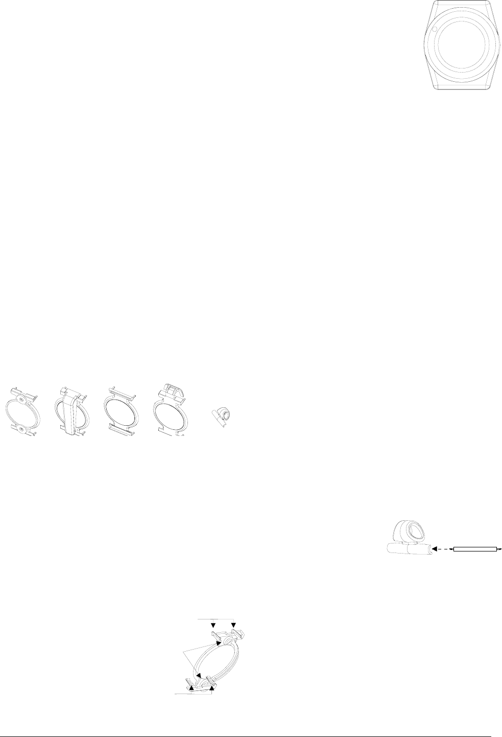
The button has five adapters which easily fit onto the panic
button. Using these adapters, the panic button can be
mounted on the wall, worn as a belt clip, as a watch, or as a
pendant.
Figure 1. Panic Button Adapters
Installation Guidelines
Use the following guidelines when installing this button.
❑The transmitter in the button has an open-air range of
up to 500 feet, but the installation environment may
influence this range.
Wall Mount Adapter
1. Place the wall mount adapter
on the wall at the desired
location and mark through the
mounting holes with a pencil.
2. Secure the holder to the wall
with the screws supplied. Use
the anchors supplied where
studs are not present.
3. Snap the panic button onto the four snap-on posts on
the wall mount adapter.
Belt Clip Adapter
The belt clip adapter is very easy to use. Simply snap the
panic button onto the four snap-on posts on the belt clip
adapter.
Wrist Adapter
The panic button can be worn on the wrist two different
ways. Using a plastic wrist band with spring loaded pins or
with a velcro wrist band.
❑Plastic Wrist Band - To use the plastic wrist band,
compress the spring-loaded pins with a small screw
driver and slip into the pin slots located on the back of
the panic button. The plastic wrist band or almost any
other 18 mm watch band can be used.
❑Velcro Wrist Band - To use the velcro wrist band, first
snap the panic button onto the four snap-on posts on the
wrist band adapter. Next, thread the band through the
slots on the ends of the adapter.
Pendant Adapter
The panic button can be worn as a pendant two different
ways. It can be worn with a necklace by using the pin-
mounted necklace adapter, or it can be worn with the rope
necklace that comes with it using the snap-on pendant
adapter.
To use the pin-mounted necklace adapter:
1. Check to make sure the necklace or chain fits through
the larger hole in the pin-mounted necklace adapter.
2. Remove one of the
spring-loaded pins
from the plastic wrist
band and insert it into
the smaller hole on the
necklace adapter.
3. Compress the spring-
loaded pins with a small screw driver and slip into the
pin slots located on the back of the panic button.
8958G10A.DSF
WALL MOUNT
ADAPTER BELT CLIP
ADAPTER WRIST BAND
ADAPTER PENDANT
ADAPTER
PIN-MOUNTED
NECKLACE
ADAPTER
Wall
Mount
Adapter
Pendant
Adapter
Velcro
Wrist Band
Adapter
Belt
Clip
Adapter
Pin-Mounted
Necklace
Adapter
MOUNTING
HOLES
SNAP-ON
POSTS
S
NAP-ON
POSTS
Snap-On
Posts
Mounting
Holes
Snap-On
Posts
PIN-MOUNTED
NECKLACE
ADAPTER
SPRING-LOADED
PIN
Spring-Loaded
Pin
Pin-Mounted
Necklace
Adapter
0LFUR:ULVWZDWFK3DQLF
%XWWRQ
ITI Part No. 60-XXX
Document Number: L66-1815 Rev. A PRELIMINARY
September 2001
8958
g
07a.ds
f
Preliminary 9/11/01
To use the pendant adapter:
1. Slip the rope necklace into the
top slot on the pendant adapter
and hook the plastic ends
together.
2. Snap the panic button onto the
four snap-on posts on the pen-
dant adapter.
Programming
This section describes the basic steps for adding the panic
button sensor to panel memory. For complete instructions,
refer to the specific panel’s installation instructions.
1. Set the panel in the program mode.
2. Enter the appropriate group number (groups 00 through
07) when prompted by the panel.
3. Select the desired sensor number when prompted by
the panel.
4. When prompted by the panel, trip the sensor by press-
ing the button.
5. Exit from program mode.
Testing the Panic Button
This section describes the basic steps for testing the panic
button. For complete instructions, refer to the specific
panel’s installation instructions.
1. Set the system to the Dealer Sensor Test mode.
2. Press the button on the sensor.
3. Listen for beeps sounded from system sirens.
4. Test the panic button sensor from several locations
within the premises to check for consistent response.
Replacing the Battery
You must be free of all static electricity before handling the
transmitter circuit board. Touch a grounded, bare metal
surface before touching the circuit board, or wear a
grounding strap.
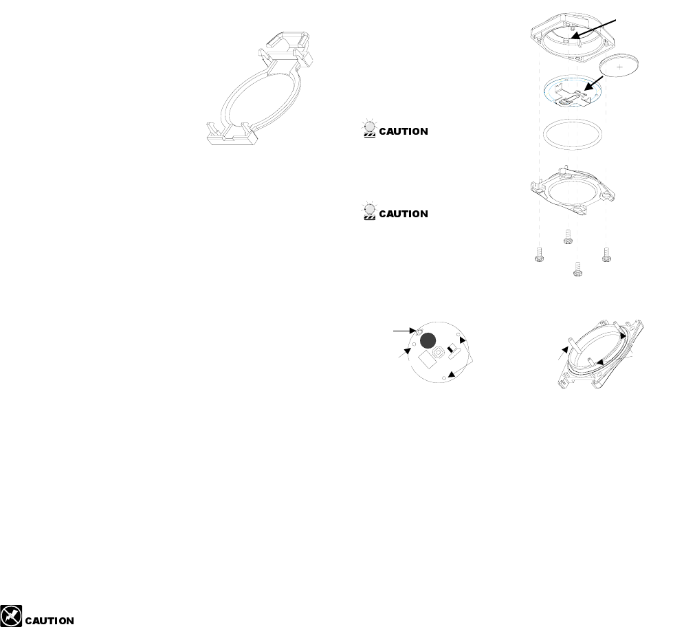
1. Disassemble the button by removing the four screws on
the back of the button and separate the cover and base.
Note
Many need to “rock” the cover to loosen it due to the tight
seal created by the o-ringRemove the old battery from its
holder and install the new battery, observing polarity.
Note
Install only Duracell
DL2032.
2. Reassemble the but-
ton. Make sure to line
up the LED indicator
bump on the cover with
the LED on the PCB.
If the board is not
correctly lined up with
the cover, it can create
stress on the plastic.
Be sure to assemble
the panic button
correctly to ensure
water resistance. Be
especially careful not to
nick or damage the
rubber o-ring.
3. Test the sensor as described in “Testing the Panic But-
ton” section.
Lithium Battery Disposal
Lithium batteries that are no longer usable are considered
hazardous waste. Be sure to properly dispose of the old bat-
tery. Contact your local city government for hazardous
waste disposal laws.
Specifications
Compatibility: ......................All ITI Learn Mode Panels
Power Source: ......................3.0 VDC Duracell (DL2032)
Lithium Battery (will last at
least 12 months)
Temperature:
Operating ..............................32° to 120° F (0° to 49° C)
Storage..................................-30° to 140° F (-34° to 60° C)
Maximum Humidity .............90% Relative Humidity,
non-condensing
Enclosure: ............................Water-Resistant
Dimensions w/o adapters
or wrist bands: .....................1.5” x 1.3” x .5” (L x W x D)
Listings
UL 636: Holdup Alarm Units and Systems (applied for)
UL 1023: Household Burglar Alarm System Units
(applied for)
PENDANT
ADAPTER
Pendant
Adapter
BASE
RUBBER
O-RING
PCB
BATTERY
COVER
8958g05a.dsf
LED
INDICATOR
BUMP
Cover
Battery
Rubber
O-Ring
PCB
LED
LINE UP
WITH LONGEST
MOUNTING POST
MOUNTING
HOLES OTHER
MOUNTING
POSTS
LONGEST
MOUNTING
POST
Mounting
Holes
LED
Line up
Mounting Post
with Widest
Widest
Mounting
Post
Other
Mounting
Posts

3
Micro Wristwatch Panic Button
Notices
Preliminary 9/11/01
UL 1610: Central Station Burglar Alarm Units (applied for)
UL 1637: Home Health Care Signaling Equipment
(applied for)
Notices
This device complies with FCC Rules Part 15. Operation is subject to the
following two conditions.
This device may not cause harmful interference.
This device must accept any interference that may be received, including
interference that may cause undesired operation.
Changes or modifications not expressly approved by Interactive Technolo-
gies, Inc. can void the user’s authority to operate the equipment.
FCC ID: B4Z-781A-PANIC (located on back of Panic Button).
US Patents 4,855,713; 4,864,636, and others pending.
2266 Second Street North | North Saint Paul Mn | 55109 | 800-777-2624 | www.interlogixinc.com
©2001 Interlogix,™ Inc. Interlogix is a trademark of Interlogix, Inc. ITI, is a registered trademark of Interlogix, Inc.