UTC Fire and Security Americas 785B-ALTP Dialog QS1000 Remote Station User Manual
UTC Fire & Security Americas Corporation, Inc. Dialog QS1000 Remote Station
User Manual
1
,QVWDOODWLRQ,QVWUXFWLRQV
*(,QWHUORJL[
'
Product
Summary
The Dialog™ QS1000 Allegro Remote Station is a wireless wall-mount remote station designed
to provide remote security system control and status checking. The Remote Station allows the
user to perform the following functions:
• Arming and Disarming
• Activating Police, Auxiliary and Fire Panic Alarms
• Checking of System Status
The remote station has the following features:
• One Hardwire Input
• Built-in Siren
• Wall Tamper
• Custom Liquid Crystal Display (LCD)
• Armed and Ready LEDs
Programming The following steps describe the general process for programming (learning) the remote station
into panel memory. Refer to the specific panel Installation Instructions or Reference Manual for
complete programming details.
¾To program the remote station into the system:
1. Enter the appropriate code to access the panel menus.
2. Enter the panel Learn/Add Sensors/Devices menu.
3. Change the sensor number if necessary.
4. Press and hold both Police Panic buttons on the remote station.
¾To set the volume of status beeps from the remote station:
1. Press and hold the 8 button. The remote station will beep every 2 seconds.
2. Release the button when the desired volume is reached.
Mounting Use the following procedure to mount remote station to the wall or wall studs.
¾To mount the remote station:
1. Remove the remote station from the back mounting plate by lifting
the tab located on the top and pulling back.
2. Remove the wiring knockout.
3. Feed all device wires through the knockout and place the back
mounting plate in position against the wall.
4. Level the back mounting plate and mark the top and bottom mounting holes.
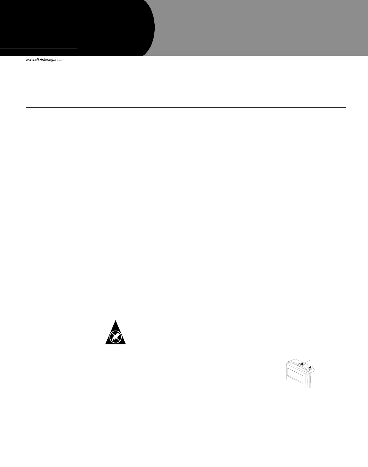
You must be free of static electricity before handling circuit boards. Wear a grounding
strap or touch a bare metal surface to discharge static electricity.
Static
Tab
Antenna
(Standard)
Figure 1. Tab location
'RFXPHQW1XPEHU5HY$
6HSWHPEHU
35(/,0,1$5<
Preliminary 9/19/03
'LDORJ46
$OOHJUR5HPRWH6WDWLRQ
3DUW1R5
2Allegro Remote Station Installation Instructions
Preliminary 9/19/03
Note
The wiring knockout is
approximately the same
width as a wall stud. If
mounting the remote station
to a wall stud be sure you
have enough room to feed
the wires through the knock-
out.
5. Install anchors where studs are not present.
6. Partially insert a screw into the top mounting hole location then hang the back mounting
plate on the screw.
7. Recheck for level, insert the lower screw, and tighten both mounting screws.
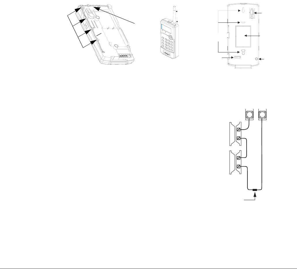
8. Install the antenna. There are three antenna options to choose from:
•Standard Range- Leave the antenna as is.
•Extended Range - Attach the optional antenna housing (included in the accessory
pack) to the remote station.
a.Push the antenna housing down into the top right hole of the remote station until it
snaps into place (see Figure 2).
b.Remove the antenna loop from the last clip on the remote station cabinet and insert
it into the antenna housing.
•Longest Range - Hang the antenna in the wall.
a.When you mark the back mounting plate’s two mounting holes, also mark where
the antenna hole is (see Figure 2 for antenna wire hole location).
b.Where the antenna hole was marked, drill a hole into the wall.
c.Remove the antenna loop (see Figure 2) from the remote station cabinet clips and
feed through the antenna hole and down into the wall.
Figure 2. Antenna configurations
9. Place the remote station cabinet into the back mounting plate and snap into place.
Connecting Detection Devices to the
remote station
The remote station has one hardwire input. The input is
supervised using a 2.2 k Ohm, end-of-line (EOL) resis-
tor (included with the remote station) at the last device
on the circuit. It accepts normally closed (N/C) detec-
tion devices. Figure 3 shows the typical wiring for a N/
C door/window intrusion detection.
The maximum loop resistance for each zone input is
300 ohms, plus the 2.2 k Ohm EOL resistor.
Important !
The 2.2 kOhm EOL resistor must be installed across termi-
nal 3 and 4 even when no detection device is connected. If
this is not done the panel will indicate the zone is open.
Clips
Antenna
Loop
6087495g02a.dsf
Antenna
Housing
Push Down
Into Panel
Antenna Wiring Optional Antenna Housing
Antenna
Wire Hole
Wire
Clip
Mounting Knockout
Tamper
Switch
Holes
Wiring Hole (Longest Range)
(Extended Range)
(Standard Range)
Panel Terminals
Normally
Closed
(N/C)
Contacts
In Series
3 4
Figure 3. Wiring N/C Intrusion
Detection devices
2.2 k Ohm
EOL Resistor
49-467
3Allegro Remote Station Installation Instructions
Preliminary 9/19/03
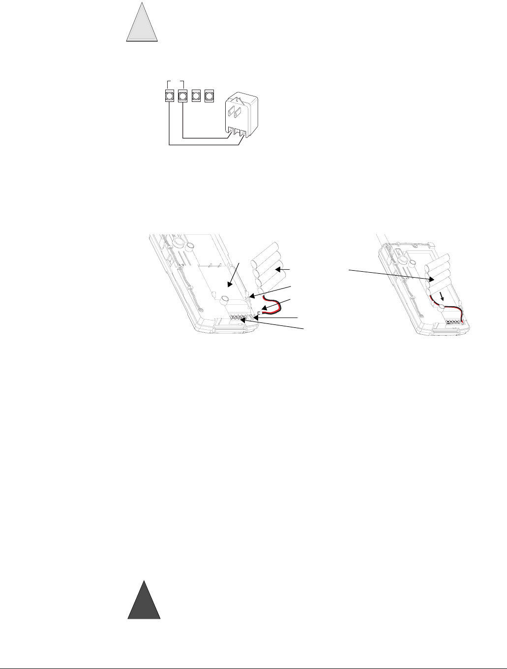
Connecting the AC Power Transformer
The remote station must be powered by a UL
approved transformer. Connect the power trans-
former to the panel as shown in Figure 4.
Note
In Canada, use the AC
power transformer without a
securing tab, (part no. 22-
117-CN).
Connecting the Backup Battery Pack
The remote station will receive its primary power from an AC class II transformer. In the event of
an AC power failure, the remote station will be powered by a battery pack containing four
rechargeable NiCd batteries.
Figure 5. Connecting the Battery Pack
¾To connect the backup battery pack:
1. Remove the panel housing from the back mounting plate by lifting the tab located on the top
of the remote station and pulling back.
2. Slide the battery pack into the space provided on the back of the remote station (Figure 5).
Note
Be sure to run the battery
pack wires below the battery
and through the wire chan-
nel.
3. Plug the battery pack lead into the slot provided next to the wire terminals
(Figure 5).
4. Replace the remote station housing on the back mounting plate and snap into place.
Note
Verify the front door is in place before replacing the panel on the mounting plate. It is not possible to
attach the door after the panel is secured to the mounting plate.
Powering Up the Remote Station
After connecting and wiring all devices to the panel, you are ready to apply AC power to the
panel.
¾To power up the panel:
Plug the transformer into an outlet that is not controlled by a switch or ground fault circuit
interrupt (GFCI). Be sure to screw the top of the transformer onto the outlet so that it doesn’t
fall out of the outlet.
Do not plug in the power transformer at this time. The panel must be powered up using
the sequence of steps described in the “Powering up the Panel” section.
Caution
!
3
4
1
2
Z
C
O
M
Z
O
N
E
AC
Figure 4. Connecting a Power Transformer
Battery
Location
Wire Terminals
Pack
Battery Pack
Wire Channel
Battery Pack
Lead
Battery Connector
Be careful when securing the transformer to an outlet with a metal cover. Hold the cover
tightly in place. You could receive a serious shock if the metal outlet cover drops onto the
prongs of the plug while you are securing the transformer and cover to the outlet box.
If the panel does not display anything, immediately unplug the transformer and discon-
nect the backup battery.
Warning
!

4Allegro Remote Station Installation Instructions
Preliminary 9/19/03
Specifications Model No.: ................................60-982-95R
Compatibility: ..........................Allegro™ Software Version 1.3 and later
RF Frequency:..........................319.5 + or - 140 kHz
Power Source: .........................8 or 9 VAC, minimum 300 mA (Must be a GE Interlogix recommended
transformer.)
Battery Type:............................4.8 VDC rechargeable NiCd battery pack
Typical Standby Current:........
Operating Temp Range: ..........32° to 122° F (0° to 49° C)
Storage Temp Range:...............-30° to 140° F (-34° to 60° C)
Relative Humidity:...................90% non-condensing
Dimensions (in): .......................7.5 x 6.75 x 1.5 (L x W x D)
Weight (lb):...............................1.0
Installation: ..............................Wall mount
Nominal Range:........................500 Feet, (150 m) open-air receiving range
Notices This device complies with FCC Rules Part 15. Operation is subject to the following two conditions.
This device may not cause harmful interference.
This device must accept any interference that may be received, including interference that may cause undes-
ired operation.
Changes or modifications not expressly approved by GE Interlogix can void the user’s authority to operate the
equipment.
FCC ID: B4Z-785B-ALTP
2266 Second Street North
North Saint Paul MN 55109
Technical Support: 800-777-2624
)
*(,QWHUORJL[
©2003 GE Interlogix. Dialog and Allegro are trademarks of GE Inter-
logix. All other trademarks are properties of their owners.
All rights reserved.