UTC Fire and Security Americas 786A-DTIM Telephone Interface Module User Manual
UTC Fire & Security Americas Corporation, Inc. Telephone Interface Module
Contents
- 1. User manual
- 2. Install Manual
Install Manual
)
1
,QVWDOODWLRQ,QVWUXFWLRQV
*(,QWHUORJL[
Product
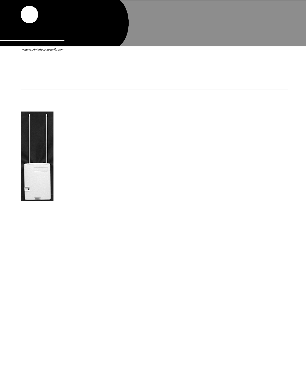
Summary The Dialog Telephone Interface Module (DTIM) is a battery operated communication link
between the security system control panel and the central monitoring station. The DTIM
receives radio signals from the panel, then uses the phone line to report security system events to
the central monitoring station.
The DTIM provides added security by separating the telephone interface from the panel. If the
panel is damaged during a break-in or fire, the DTIM can still report to the central monitoring
station.
The DTIM is a supervised device that transmits supervisory signals every hour for the panel to
receive. When the battery is low, the module transmits a low battery signal.
Note
The DTIM does not have a backup power supply. Therefore, the battery must be replaced within 7 days
when a low battery condition occurs to ensure that system events can be reported. If the battery is
allowed to completely drain, the panel identifies the DTIM as being in a supervisory (non-working)
state, which prevents system events from being reported.
Tools and Supplies Needed
• Phillips screwdriver
• Mounting Hardware (included)
• Ty-wrap and Cover Screw for UL Listed installations (included)
Installation This section describes guidelines for installing the DTIM, programming, testing, mounting, and
phone line connections.
Installation Guidelines
• Before permanently mounting to a wall, test the DTIM from the desired location to ensure
communication with the panel. This means you must first add (learn) the DTIM into panel
memory, then perform a sensor test.
• Mount the module within 100 feet of the panel, but not closer than 10 feet to another DTIM
or the panel.
• Always mount the DTIM in the upright vertical position.
• The DTIM can be connected to a standard analog (loop-start) phone line, with or without
digital subscriber line (DSL) service.
Note
The DTIM cannot be used on digital or PBX phone lines, which are designed only for digital type
devices that operate anywhere from 5 volts DC and up. The DTIM uses an analog modem and does
not have a digital converter, adapter, or interface to operate with such systems.
• When connecting the DTIM to a standard analog phone line, it is recommended that you
install an RJ-31X jack (CA-38A in Canada) ahead of all phones and other devices on the line
for full line seizure. This allows the DTIM to take control of the phone line when an alarm
occurs, even if the phone is in use or off-hook. It also provides customers with a quick dis-
connect in case the DTIM malfunctions, allowing them to use their phone.
• For UL Listed installations, mount the RJ-31X jack within 5 feet of the DTIM.
'RFXPHQW1XPEHU5HY%
2FWREHU
35(/,0,1$5<
Preliminary 10/4/02
'LDORJ7HOHSKRQH,QWHUIDF
H
0RGXOH
2Dialog Telephone Interface Module Installation Instructions
Preliminary 10/4/02
Programming—Adding the DTIM to Panel Memory
Note
We recommend learning the DTIM into Allegro panels as zone 1, since zone 1 is set up to learn
into Group 36 automatically and has pre-programmed sensor text for the DTIM (PHONE MOD-
ULE).
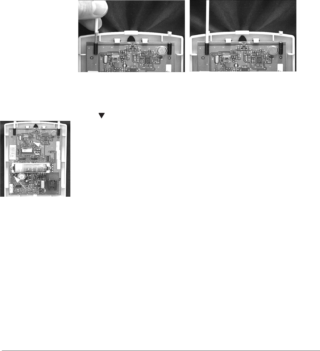
The DTIM uses a 3-2-1 tamper switch activation sequence for learning, which causes the
LED to blink in a corresponding 3-2-1 sequence. You must wait for the LED to turn off after
each flash sequence before releasing the tamper switch (see Figure 2).
To learn the DTIM into the panel:
1. Remove the DTIM cover and install the antennas (see Figure 1).
Figure 1. Antenna Installation
Note
Antennas must be installed for learning.
2. With the system disarmed, enter program mode at the Allegro panel by pressing
8 + CODE.
3. Press twice and ƒ twice. The Allegro display shows ZONE 01 - TRIP.
4. Locate the DTIM tamper switch and LED (see Figure 2 at left).
Important !
Timing is the key to success with step 5. Read the complete step before you begin to help
ensure successful programming. Do not wait more than 1 second between tamper switch activa-
tions in step 5. If you wait too long, the LED will not flash and you must start over. Also, do not
release the tamper switch before the LED is done flashing or you must start over.
5. Press and release the DTIM tamper switch as follows:
Press 3 times, holding the tamper switch down on the third press until the LED flashes 3
times, then release after the third flash.
Immediately press 2 times, holding the tamper switch down on the second press until the
LED flashes 2 times, then release after the second flash.
Immediately press and hold until the LED flashes 1 time, then release the tamper switch.
6. Exit from program mode.
Testing DTIM Transmitting Range
The following describes the basic steps for testing transmitting range from the DTIM to the
panel. For complete testing instructions, see the panel installation instructions.
Note
Be sure to attach the cover onto the DTIM before testing wireless communications.
1. Place the DTIM in the desired location.
2. Put the Allegro panel into sensor test mode. The panel piezo should sound 7 - 8 beeps.
This indicates good reception from the DTIM to the panel.
3. If you hear fewer than 7 beeps, test the DTIM in different locations. Mounting locations
should be limited to areas where the panel responds with 7 - 8 beeps.
4. To retest transmitting range after relocating the DTIM, press ‚ then ƒ at the Allegro
panel and listen for 7 - 8 beeps.
5. Exit from test mode after determining acceptable locations.
Align antenna.. ...push down until bare metal is
not visible. Repeat for other
antenna.
LED
Tamper Switch
Figure 2. Tamper Switch and
LED Locations
3Dialog Telephone Interface Module Installation Instructions
Preliminary 10/4/02
Mounting
After finding an acceptable mounting location (based on testing), mount the DTIM as described.
You must be free of static electricity before handling circuit boards. Touch a bare metal surface or wear
a grounding strap to discharge yourself.
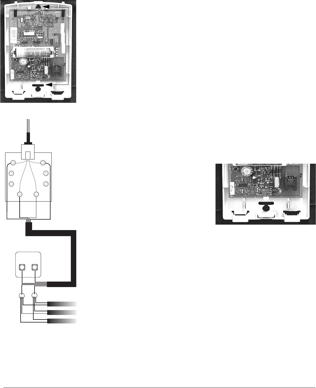
1. With the cover off, place the DTIM at the desired location and mark the mounting holes (see
Figure 3 at left).
2. Make holes in the wall for anchors at the marked locations.
3. Insert wall anchors where necessary, then use two #6 screws to secure the DTIM to the wall.
Wiring a Phone Line to the Module
Connect the DTIM ahead (or in front) of all other phones, answering machines, computers, or any
other devices on the phone line. This allows the DTIM to take over (seize) the phone line, even if
another device on the line is in use.
An RJ-31X (CA-38A) jack should be installed when wiring for full line seizure. This lets the user
quickly and easily disconnect the DTIM from the phone line in case the DTIM disables the phone
line due to a malfunction.
Note
For UL Listed systems, the RJ-31X jack must be mounted within 5 feet of the DTIM.
1. Run a 4-conductor cable from the TELCO block to the RJ-31X (A in Figure 4).
2. Connect the 4-conductor cable wires to the RJ-31X (B in Figure 4).
3. Disconnect the Green and Red premises phone jack wires from the TELCO block and splice
them to the 4-conductor cable Black and White (or Yellow) wires (C in Figure 4). Use weath-
erproof wire connectors for these splices.
4. Connect the 4-conductor cable Green and Red wires to the TELCO block TIP (+) and Red to
RING (-) posts (D in Figure 4).
5. Insert the 8-conductor phone cord plug into the RJ-31X jack (E in Figure 4).
6. Remove the right knockout on the DTIM plastic,
feed the 4-conductor phone cord plug through it
and connect the plug into the DTIM phone jack
(Figure 5 at right).
Phone Test
After connecting the phone line to the DTIM, conduct
a phone test to verify reports are made to the central
monitoring station. The following steps describe the
basic steps for conducting a phone test. Refer to the
specific panel installation instructions for complete
details.
Note
You must conduct a phone test whenever the DTIM battery is replaced.
1. Call the central monitoring station to inform them you are testing the system.
2. Make sure the panel has the correct account number and central station receiver phone num-
ber programmed.
3. Enter the appropriate phone test command for the panel used in the system.
4. Contact the central monitoring station when you are finished testing.
Installing the Battery Ty-wrap and Cover Screw (UL Listed
Installations Only)
After installation, programming, and testing are completed install the Ty-wrap around the battery
and battery holder. Cut off any access.
Secure the cover with the cover screw by installing it through the cover push tab.
Figure 3. Mounting Hole Locations
A
B
C
D
TIP
(+) RING
(-)
BRN GRY
GRN RED
Green Red
White (or Yellow)
Black
Black
Green
Red
White
(or Yellow)
E
Knockout
Removed
Phone
Jack
Figure 5. Knockout and Phone Jack Locations
Figure 4. RJ31X Phone Wiring

4Dialog Telephone Interface Module Installation Instructions
Preliminary 10/4/02
Trouble-
shooting Note
Disconnect the phone line from the DTIM before servicing.
No Dial Tone
If there is no dial tone at on-site phones after wiring the RJ-31X jack, use the following to find the
cause.
• Wait 2 minutes and try again. The DTIM may be busy trying to report to the central station.
• Check the DB-8 cord connections at the module and RJ-31X jack. Replace the cord if neces-
sary.
• Disconnect the DB-8 cord from the RJ-31X jack. If the phone still doesn’t work, the problem
is in the RJ-31X jack wiring. Check the RJ-31X jack wiring and TELCO block wiring.
Replace the RJ-31X jack if necessary.
•Perform a phone test after troubleshooting the phone line (see your panel installation instructions
for phone test procedures).
Constant Dial Tone
• If a constant dial tone prevents you from using the phone, there may be one or more polarity-
sensitive phones on the premises. Reverse the phone wires connected to the brown and gray wire
terminals on the RJ-31X jack.
No System Response
If the system does not respond in sensor test (as described in the panel installation instructions),
try the following:
• Change the antenna position. Best range is achieved by inserting the antenna into the wall.
• Check that the DTIM battery is installed.
• Check the DTIM for a dead battery. Replace the battery if necessary.
• Use an RF Sniffer (60-401) to verify that the DTIM is transmitting.
• Verify that the DTIM was added (learned) into panel memory correctly.
Trouble Condition
• The tamper switch may have been tripped. Check that the cover is securely in place.
• The DTIM battery may be low. Check the battery, replace if necessary and conduct a phone
test.
Module Supervisory
• If the panel indicates a DTIM supervisory condition, use an RF Sniffer (60-401) to verify that
the DTIM transmits when the tamper switch is pressed. If it does not transmit, check the bat-
tery and replace it if necessary.
• If the sniffer indicates that the DTIM is transmitting, it may be out of panel receiving range.
Use the sensor test to verify that the DTIM is within panel range. If necessary, test the DTIM
from other locations until an acceptable location is found.
Specifications Compatibility: ..............Allegro™
Wireless Range .............500 feet open-air (nominal)
Power Source: .............. 3.6 V AA Lithium Battery
Storage Temperature:.... -30° F to 140° F (-34° C to 60° C)
Operating Temperature: 32° F to 120° F(0° C to 49° C)
Maximum Humidity: ... 90% relative humidity, noncondensing
Dimensions: 4.6” (12 cm) W, 6.6” (3 cm) H, 1.20” (17 cm) D
US Patents 4,855,713 and 4,864,636
5Dialog Telephone Interface Module Installation Instructions
Preliminary 10/4/02
Notices FCC Part 15 Information to the User
Changes or modifications not expressly approved by Interlogix, Inc. can void the user’s authority to operate the equip-
ment.
FCC Part 15 Class B
This equipment has been tested and found to comply with the limits for a Class B digital device, pursuant to part 15 of the
FCC Rules. These limits are designed to provide reasonable protection against interference in a residential installation.
This equipment generates, uses, and can radiate radio frequency energy and, if not installed and used in accordance with
the instructions, may cause harmful interference to radio communications. However, there is no guarantee that interfer-
ence will not occur in a particular installation.
If this equipment does cause harmful interference to radio or television reception, which can be determined by turning the
equipment off and on, the user is encouraged to try to correct the interference by one or more of the following measures:
Reorient or relocate the receiving antenna.
Increase the separation between the equipment and receiver.
Connect the affected equipment and the panel receiver to separate outlets, on different branch circuits.
Consult the dealer or an experienced radio/TV technician for help.
FCC Part 15 ID No. B4Z-786A-DTIM
ACTA Part 68
This equipment complies with Part 68 of the FCC Rules. Located on this equipment is a label that contains, among other
information, the FCC registration number and the ringer equivalence number (REN) for this equipment. If requested, this
information must be provided to the telephone company.
FCC Part 68 Registration No. B4ZAL01B46059
The REN is used to determine the maximum number of devices that may be connected to your telephone line. Excessive
RENs on a telephone line may result in devices not ringing in response to an incoming call. In most areas, the sum of all
device RENs should not exceed five (5.0). To be certain of the number of devices that may be connected to a line, as deter-
mined by the total RENs, contact the local telephone company. For products approved after July 23, 2001, the REN for
this product is part of the product identifier that has the format US:AAAEQ##TXXXX. The digits represented by ## are
the REN without a decimal point (e.g., 03 is a REN of 0.3). For earlier products, the REN is separately shown on the label.
A plug and jack used to connect this equipment to the premises wiring and telephone network must comply with the appli-
cable FCC Part 68 rules and requirements as adopted by ACTA. A compliant telephone cord and modular plug is provided
with this product. It is designed to be connected to a compliant modular jack that is also compliant. See the Installation
Instructions for details.
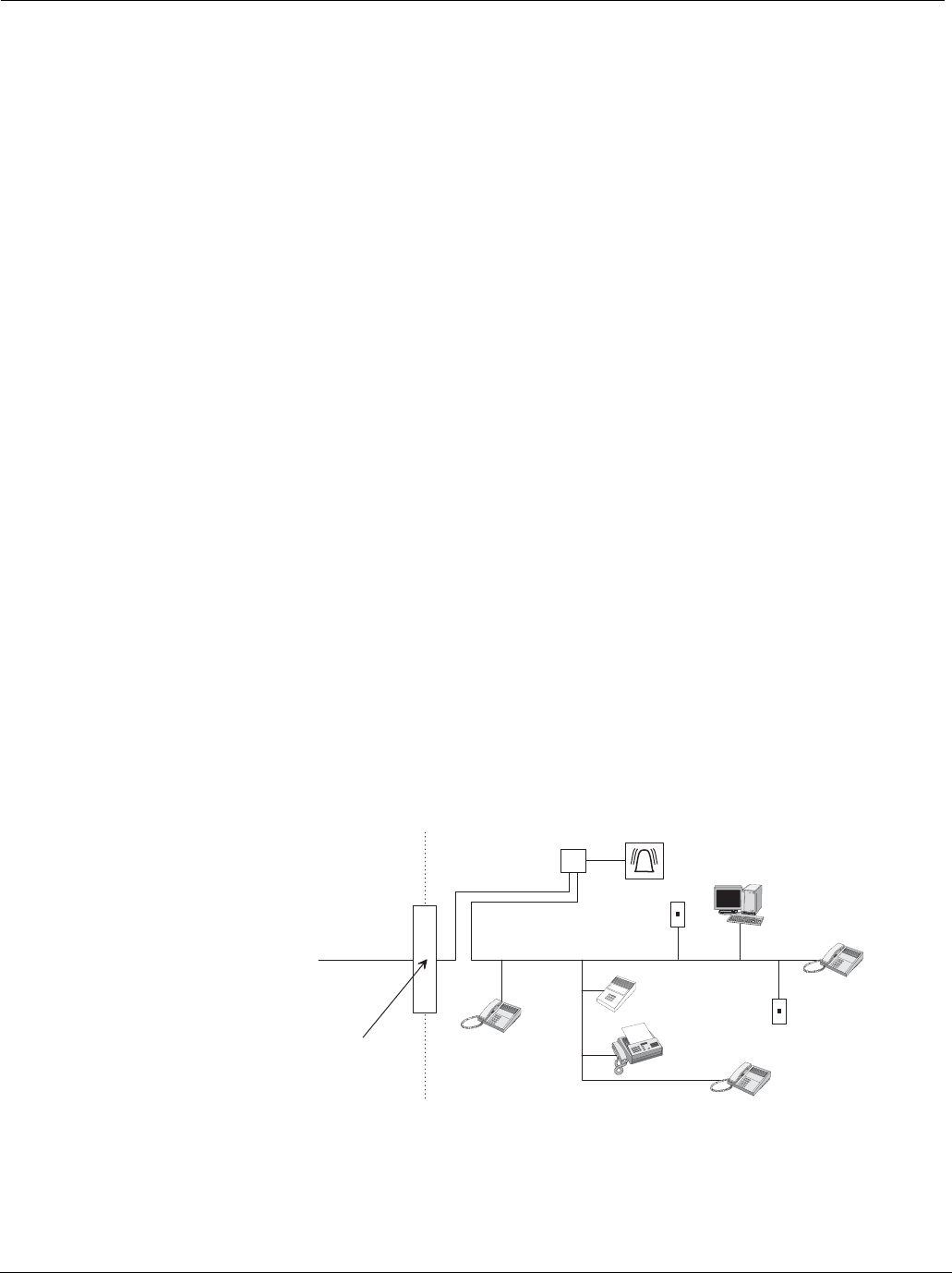
Alarm dialing equipment must be able to seize the telephone line and place a call in an emergency situation. It must be
able to do this even if other equipment (telephone, answering system, computer modem, etc.) already has the telephone
line in use. To do so, alarm dialing equipment must be connected to a properly installed RJ31X jack that is electrically in
series and ahead of all other equipment attached to the same telephone line. Proper installation is depicted in the following
diagram. If you have any questions concerning these instructions, consult your local telephone company or a qualified
installer about installing an RJ31X jack and alarm dialing equipment for you.
If this equipment causes harm to the telephone network, the telephone company may temporarily disconnect your service.
If possible, you will be notified in advance. When advance notice is not practical, you will be notified as soon as possible.
You will also be advised of your right to file a complaint with the FCC.
The telephone company may make changes in its facilities, equipment, operations, or procedures that could affect the
operation of the equipment. You will be given advance notice in order to maintain uninterrupted service.
N e t w o r k
S e r v i c e
P r o v i d e r ' s
F a c i l i t i e s
Telephone
L i n e
N e t w o r k
D e m a r c a t i o n
P o i n t
Telephone
A n s w e r i n g
S y s t e m
F a x M a c h i n e
C o m p u t e r
Telephone
Telephone
A l a r m D i a l i n g
E q u i p m e n t
R J 3 1 X
J a c k
U n u s e d
R J - 1 1 J a c k
U n u s e d
R J - 1 1 J a c k
C u s t o m e r P r e m i s e s E q u i p m e n t a n d W i r i n g

6Dialog Telephone Interface Module Installation Instructions
Preliminary 10/4/02
If you experience trouble with this equipment, please contact the company that installed the equipment for service and/or
repair information. The telephone company may ask you to disconnect this equipment from the network until the problem
has been corrected or you are sure that the equipment is not malfunctioning.
This equipment may not be used on coin service provided by the telephone company. Connection to party lines is subject
to state tariffs.
Declaration of Conformity (DoC)
GE Interlogix, Inc. declares that the model no. 60-879-95R is in conformity with Part 15 of the FCC Rules. Operation of
this product is subject to the following two conditions: (1) This device may not cause harmful interference, and (2) this
device must accept any interference received, including interference that may cause undesired operation.
Canada Notice
The Canadian Department of Communications label identifies certified equipment. This certification means that the
equipment meets certain telecommunications network protective, operational, and safety requirements. The department
does not guarantee the equipment will operate to the user’s satisfaction.
Before installing this equipment, users should ensure that it is permissible to be connected to the facilities of the local tele-
communications company. The equipment must also be installed using an acceptable method of connection. In some
cases, the company’s inside wiring associated with a single-line individual service may be extended by means of a certi-
fied connector assembly (telephone extension cord). The customer should be aware that compliance with the above condi-
tions may not prevent degradation of service in some situations.
Repairs to certified equipment should be made by an authorized Canadian maintenance facility designated by the supplier.
Any repairs or alterations made by the user to this equipment, or equipment malfunctions, may give the telecommunica-
tions company cause to request the user to disconnect the equipment.
For your protection, make sure that the electrical ground connections of the power utility, telephone lines, and internal
metallic water pipe system, if present, are connected together.
Do not attempt to make connections yourself. Contact the appropriate electrician or electric
inspections authority.
The Load Number (LN) assigned to each terminal device denotes the percentage of the total load to be connected to a tele-
phone loop that is used by the device to prevent overloading. The termination on a loop may consist of any combination of
devices subject only to the requirement that the total of the LNs of all the devices does not exceed 100. Load Number:
0.2B AC
The term “IC:” before the certification/registration number only signifies that the Industry Canada technical specifica-
tions were met.
IC: 867A 786DTIM
“AVIS: - L ´étiquette du ministère des Communications du Canada identifie le matériel homologué. Cette étiquette certifie
que le matériel est conforme a certaines normes de protection, d ´ exploitation et de sécurité des réseaux de télécommuni-
cations. Le ministère n ´ assure toutefois pas que le matériel fonctionnera a la satisfaction de l ´ utilisateur.
Avant d ´ installer ce matériel, l ´ utilisateur doit s ´ assurer qu´ il est permis de le raccorder aux installations de l ´ enter-
prise locale de télécommunication. Le matériel doit également etre installé en suivant une méthod acceptée de raccorde-
ment. Dans certains cas, les fils intérieurs de l´ enterprise utilisés pour un service individuel a ligne unique peuvent etre
prolongés au moyen d´ un dispositif homologué de raccordement (cordon prolongateur téléphonique interne). L ´ abonné
ne doit pas oublier qu ´ il est possible que la conformité aux conditions énoncées ci-dessus n ´ empechent pas le dégrada-
tion du service dans certaines situations. Actuellement, les enterprises de télécommunication ne permettent pas que l ´ on
raccorde leur matériel a des jacks d ´ abonné, sauf dans les cas précis prévus pas les tarrifs particuliers de ces enterprises.
Les réparations de matériel homologué doivent etre effectuées pas un centre d ´ entretien canadien autorisé désigné par le
fournisseur. La compagne de télécommunications peut demander a l ´ utilisateur de débrancher un appareil a la suite de
réparations ou de modifications effectuées par l ´ utilisateur ou a cause de mauvais fonctionnement.
Pour sa propre protection, l ´ utilisateur doit s ´ assurer que tous les fils de mise a la terre de la source d ´ énergie élec-
trique, des lignes téléphoniques et des canalisations d ´´ eau métalliques, s ´ il y en a, sont raccordés ensemble. Cette pré-
caution est particulièrement importante dans les régions rurales.
Avertissment. - L ´ utilisateur ne doit pas tenter de faire ces raccordements lui-meme; il doit avoir recours a un service d ´
inspection des installations électriques, ou a electricien, selon le cas”.
Une note explicative sur les indices de charge (voir 1.6) et leur emploi, a l ´ intention des utilisateurs du matériel terminal,
doit etre incluse dans l ´ information qui accompagne le materiel homologué. La note pourrait etre rédigée selon le modèle
suivant:
“L ´ indice de charge (IC) assigné a chaque dispositif terminal indique, pour éviter toute surcharge, le pourcentage de la
charge totale qui peut etre raccordée a un circuit téléphonique bouclé utilisé par ce dispositif. La terminaison du circuit
bouclé peut etre constituée de n ´ import somme des indices de charge de l ´ ensemble des dispositifs ne dépasse pas 100.”
L ´ Indice de charge de cet produit est ____________.

7Dialog Telephone Interface Module Installation Instructions
Preliminary 10/4/02
8Dialog Telephone Interface Module Installation Instructions
Preliminary 10/4/02
)
*(,QWHUORJL[