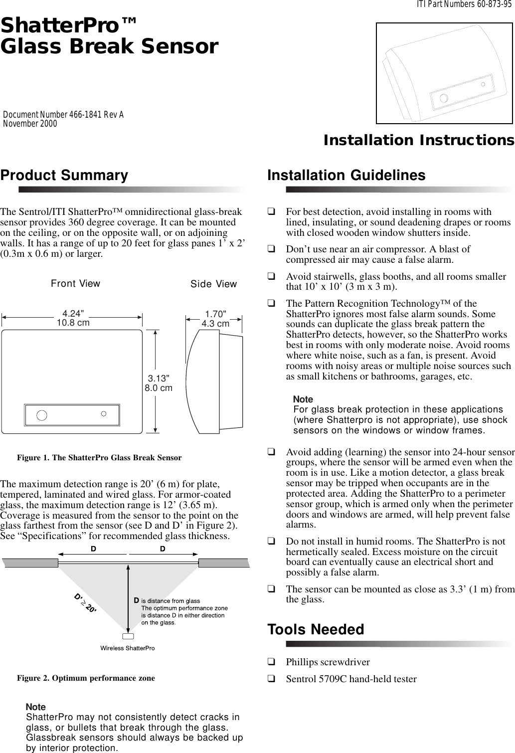
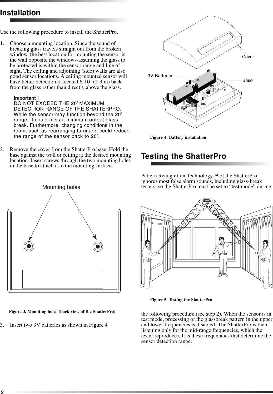
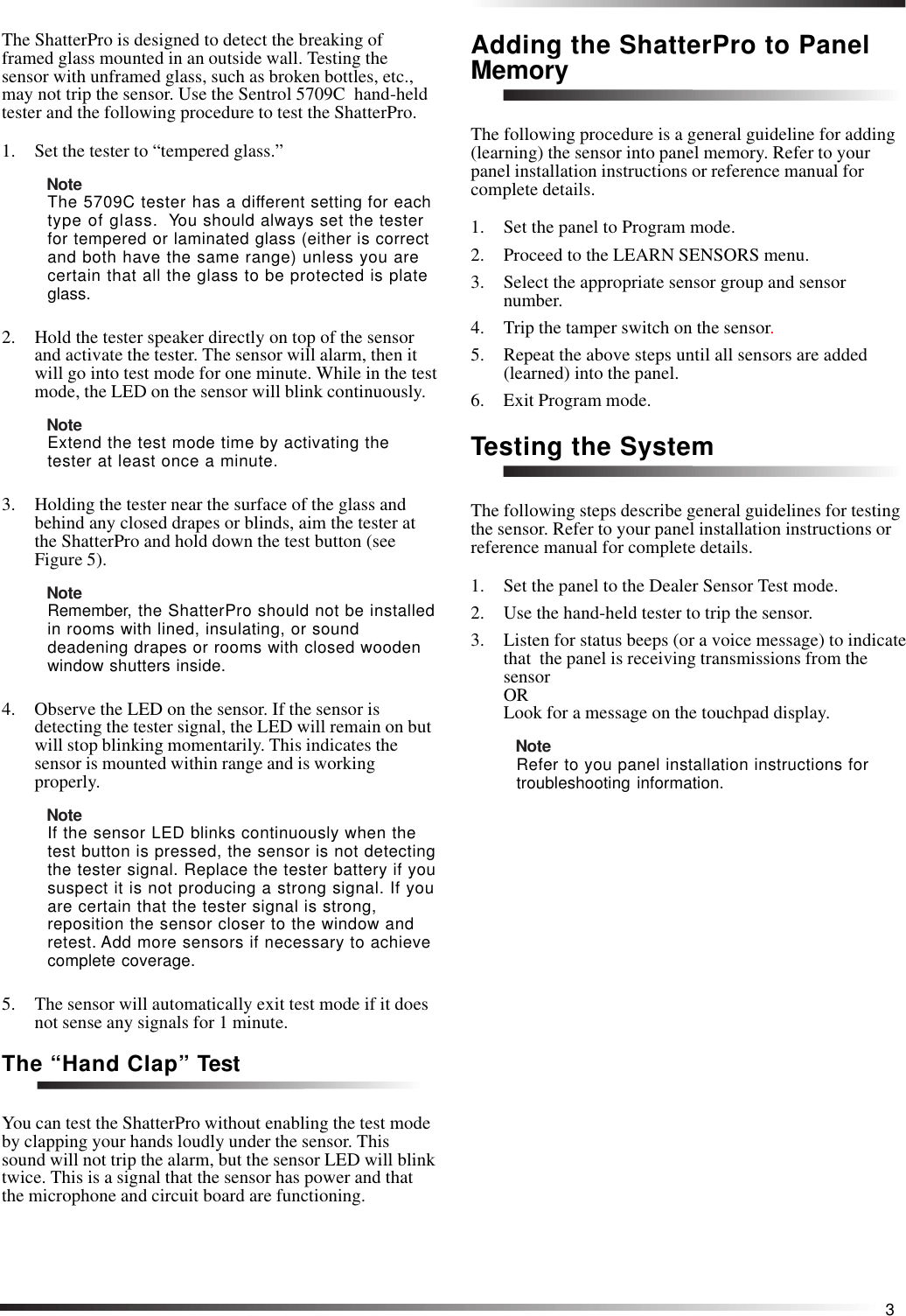
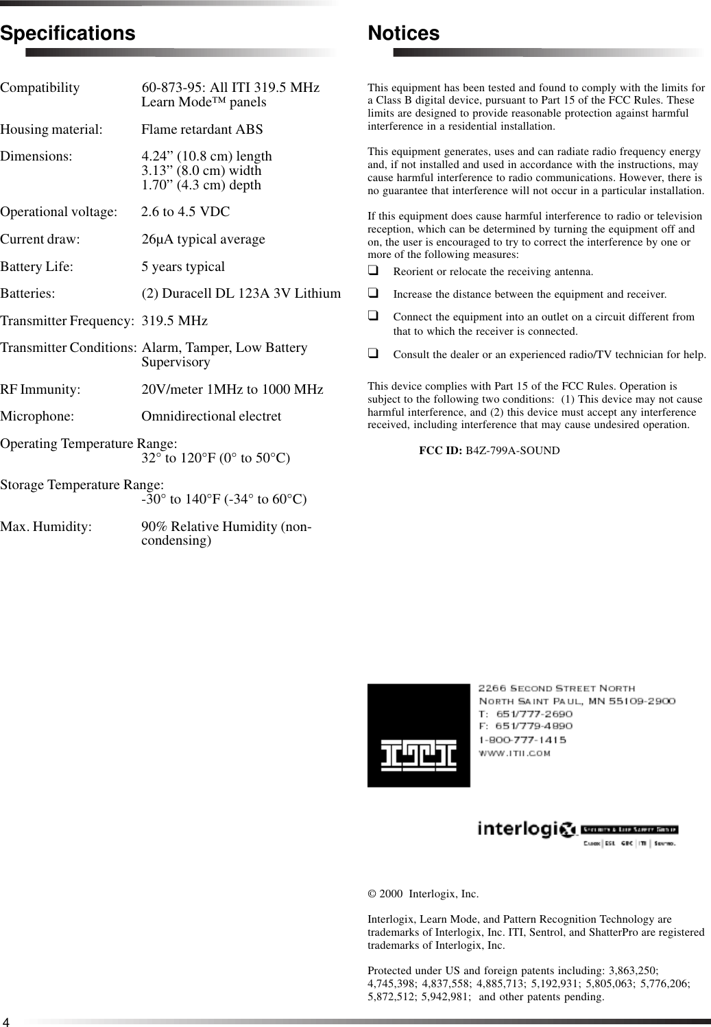
UTC Fire and Security Americas 799A-SOUND Shatter Pro (Glass Beak Detector) User Manual temptest2

UTC Fire & Security Americas Corporation, Inc. Shatter Pro (Glass Beak Detector) temptest2

User Manual

ShatterPro™Glass Break SensorInstallation InstructionsITI Part Numbers 60-873-95Document Number 466-1841 Rev ANovember 2000Product SummaryThe Sentrol/ITI ShatterPro™ omnidirectional glass-breaksensor provides 360 degree coverage. It can be mountedon the ceiling, or on the opposite wall, or on adjoiningwalls. It has a range of up to 20 feet for glass panes 1’ x 2’(0.3m x 0.6 m) or larger.Figure 1. The ShatterPro Glass Break SensorThe maximum detection range is 20’ (6 m) for plate,tempered, laminated and wired glass. For armor-coatedglass, the maximum detection range is 12’ (3.65 m).Coverage is measured from the sensor to the point on theglass farthest from the sensor (see D and D’ in Figure 2).See “Specifications” for recommended glass thickness.Figure 2. Optimum performance zoneNoteShatterPro may not consistently detect cracks inglass, or bullets that break through the glass.Glassbreak sensors should always be backed upby interior protection.Installation Guidelines❑For best detection, avoid installing in rooms withlined, insulating, or sound deadening drapes or roomswith closed wooden window shutters inside.❑Don’t use near an air compressor. A blast ofcompressed air may cause a false alarm.❑Avoid stairwells, glass booths, and all rooms smallerthat 10’ x 10’ (3 m x 3 m).❑The Pattern Recognition Technology™ of theShatterPro ignores most false alarm sounds. Somesounds can duplicate the glass break pattern theShatterPro detects, however, so the ShatterPro worksbest in rooms with only moderate noise. Avoid roomswhere white noise, such as a fan, is present. Avoidrooms with noisy areas or multiple noise sources suchas small kitchens or bathrooms, garages, etc.NoteFor glass break protection in these applications(where Shatterpro is not appropriate), use shocksensors on the windows or window frames.❑Avoid adding (learning) the sensor into 24-hour sensorgroups, where the sensor will be armed even when theroom is in use. Like a motion detector, a glass breaksensor may be tripped when occupants are in theprotected area. Adding the ShatterPro to a perimetersensor group, which is armed only when the perimeterdoors and windows are armed, will help prevent falsealarms.❑Do not install in humid rooms. The ShatterPro is nothermetically sealed. Excess moisture on the circuitboard can eventually cause an electrical short andpossibly a false alarm.❑The sensor can be mounted as close as 3.3’ (1 m) fromthe glass.Tools Needed❑Phillips screwdriver❑Sentrol 5709C hand-held tester4.24"10.8 cm 1.70"4.3 cm3.13"8.0 cmFront View Side View
2InstallationUse the following procedure to install the ShatterPro.1. Choose a mounting location. Since the sound ofbreaking glass travels straight out from the brokenwindow, the best location for mounting the sensor isthe wall opposite the window--assuming the glass tobe protected is within the sensor range and line ofsight. The ceiling and adjoining (side) walls are alsogood sensor locations. A ceiling mounted sensor willhave better detection if located 6-10’ (2-3 m) backfrom the glass rather than directly above the glass.Important !DO NOT EXCEED THE 20’ MAXIMUMDETECTION RANGE OF THE SHATTERPRO.While the sensor may function beyond the 20’range, it could miss a minimum output glass-break. Furthermore, changing conditions in theroom, such as rearranging furniture, could reducethe range of the sensor back to 20’.2. Remove the cover from the ShatterPro base. Hold thebase against the wall or ceiling at the desired mountinglocation. Insert screws through the two mounting holesin the base to attach it to the mounting surface.        Mounting holesFigure 3. Mounting holes (back view of the ShatterPro)3. Insert two 3V batteries as shown in Figure 4Figure 4. Battery installationTesting the ShatterProPattern Recognition Technology™ of the ShatterProignores most false alarm sounds, including glass-breaktesters, so the ShatterPro must be set to “test mode” duringFigure 5. Testing the ShatterProthe following procedure (see step 2). When the sensor is intest mode, processing of the glassbreak pattern in the upperand lower frequencies is disabled. The ShatterPro is thenlistening only for the mid-range frequencies, which thetester reproduces. It is these frequencies that determine thesensor detection range.CoverBase3V Batteries
3The ShatterPro is designed to detect the breaking offramed glass mounted in an outside wall. Testing thesensor with unframed glass, such as broken bottles, etc.,may not trip the sensor. Use the Sentrol 5709C  hand-heldtester and the following procedure to test the ShatterPro.1. Set the tester to “tempered glass.”NoteThe 5709C tester has a different setting for eachtype of glass.  You should always set the testerfor tempered or laminated glass (either is correctand both have the same range) unless you arecertain that all the glass to be protected is plateglass.2. Hold the tester speaker directly on top of the sensorand activate the tester. The sensor will alarm, then itwill go into test mode for one minute. While in the testmode, the LED on the sensor will blink continuously.NoteExtend the test mode time by activating thetester at least once a minute.3. Holding the tester near the surface of the glass andbehind any closed drapes or blinds, aim the tester atthe ShatterPro and hold down the test button (seeFigure 5).NoteRemember, the ShatterPro should not be installedin rooms with lined, insulating, or sounddeadening drapes or rooms with closed woodenwindow shutters inside.4. Observe the LED on the sensor. If the sensor isdetecting the tester signal, the LED will remain on butwill stop blinking momentarily. This indicates thesensor is mounted within range and is workingproperly.NoteIf the sensor LED blinks continuously when thetest button is pressed, the sensor is not detectingthe tester signal. Replace the tester battery if yoususpect it is not producing a strong signal. If youare certain that the tester signal is strong,reposition the sensor closer to the window andretest. Add more sensors if necessary to achievecomplete coverage.5. The sensor will automatically exit test mode if it doesnot sense any signals for 1 minute.The “Hand Clap” TestYou can test the ShatterPro without enabling the test modeby clapping your hands loudly under the sensor. Thissound will not trip the alarm, but the sensor LED will blinktwice. This is a signal that the sensor has power and thatthe microphone and circuit board are functioning.Adding the ShatterPro to PanelMemoryThe following procedure is a general guideline for adding(learning) the sensor into panel memory. Refer to yourpanel installation instructions or reference manual forcomplete details.1. Set the panel to Program mode.2. Proceed to the LEARN SENSORS menu.3. Select the appropriate sensor group and sensornumber.4. Trip the tamper switch on the sensor.5. Repeat the above steps until all sensors are added(learned) into the panel.6. Exit Program mode.Testing the SystemThe following steps describe general guidelines for testingthe sensor. Refer to your panel installation instructions orreference manual for complete details.1. Set the panel to the Dealer Sensor Test mode.2. Use the hand-held tester to trip the sensor.3. Listen for status beeps (or a voice message) to indicatethat  the panel is receiving transmissions from thesensorORLook for a message on the touchpad display.NoteRefer to you panel installation instructions fortroubleshooting information.
4SpecificationsCompatibility 60-873-95: All ITI 319.5 MHzLearn Mode™ panelsHousing material: Flame retardant ABSDimensions: 4.24” (10.8 cm) length3.13” (8.0 cm) width1.70” (4.3 cm) depthOperational voltage: 2.6 to 4.5 VDCCurrent draw: 26µA typical averageBattery Life: 5 years typicalBatteries: (2) Duracell DL 123A 3V LithiumTransmitter Frequency: 319.5 MHzTransmitter Conditions: Alarm, Tamper, Low BatterySupervisoryRF Immunity: 20V/meter 1MHz to 1000 MHzMicrophone: Omnidirectional electretOperating Temperature Range:32° to 120°F (0° to 50°C)Storage Temperature Range:-30° to 140°F (-34° to 60°C)Max. Humidity: 90% Relative Humidity (non-condensing)© 2000  Interlogix, Inc.Interlogix, Learn Mode, and Pattern Recognition Technology aretrademarks of Interlogix, Inc. ITI, Sentrol, and ShatterPro are registeredtrademarks of Interlogix, Inc.Protected under US and foreign patents including: 3,863,250;4,745,398; 4,837,558; 4,885,713; 5,192,931; 5,805,063; 5,776,206;5,872,512; 5,942,981;  and other patents pending.NoticesThis equipment has been tested and found to comply with the limits fora Class B digital device, pursuant to Part 15 of the FCC Rules. Theselimits are designed to provide reasonable protection against harmfulinterference in a residential installation.This equipment generates, uses and can radiate radio frequency energyand, if not installed and used in accordance with the instructions, maycause harmful interference to radio communications. However, there isno guarantee that interference will not occur in a particular installation.If this equipment does cause harmful interference to radio or televisionreception, which can be determined by turning the equipment off andon, the user is encouraged to try to correct the interference by one ormore of the following measures:❑Reorient or relocate the receiving antenna.❑Increase the distance between the equipment and receiver.❑Connect the equipment into an outlet on a circuit different fromthat to which the receiver is connected.❑Consult the dealer or an experienced radio/TV technician for help.This device complies with Part 15 of the FCC Rules. Operation issubject to the following two conditions:  (1) This device may not causeharmful interference, and (2) this device must accept any interferencereceived, including interference that may cause undesired operation.FCC ID: B4Z-799A-SOUND

Navigation menu