UTC Fire and Security Americas 799E5-SOUND 60-873-95 User Manual 9 XXX Model Name Installation Sheet
UTC Fire & Security Americas Corporation, Inc. 60-873-95 9 XXX Model Name Installation Sheet
User Manual
© DDMONYY UTC Fire & Security. All rights reserved. 1 / 6 P/N 466-5401 • REV B • 9MAY18
ShatterPro® Glassbreak Sensor
Installation Sheet
Product Summary
The ShatterPro® omnidirectional glassbreak sensor (60-873-
95) provides 360 degree coverage. It can be mounted on the
ceiling, or on the opposite wall, or on adjoining walls. It has a
range of up to 20 feet for glass panes 1' x 2' (0.3 m x 0.6 m)
or larger.
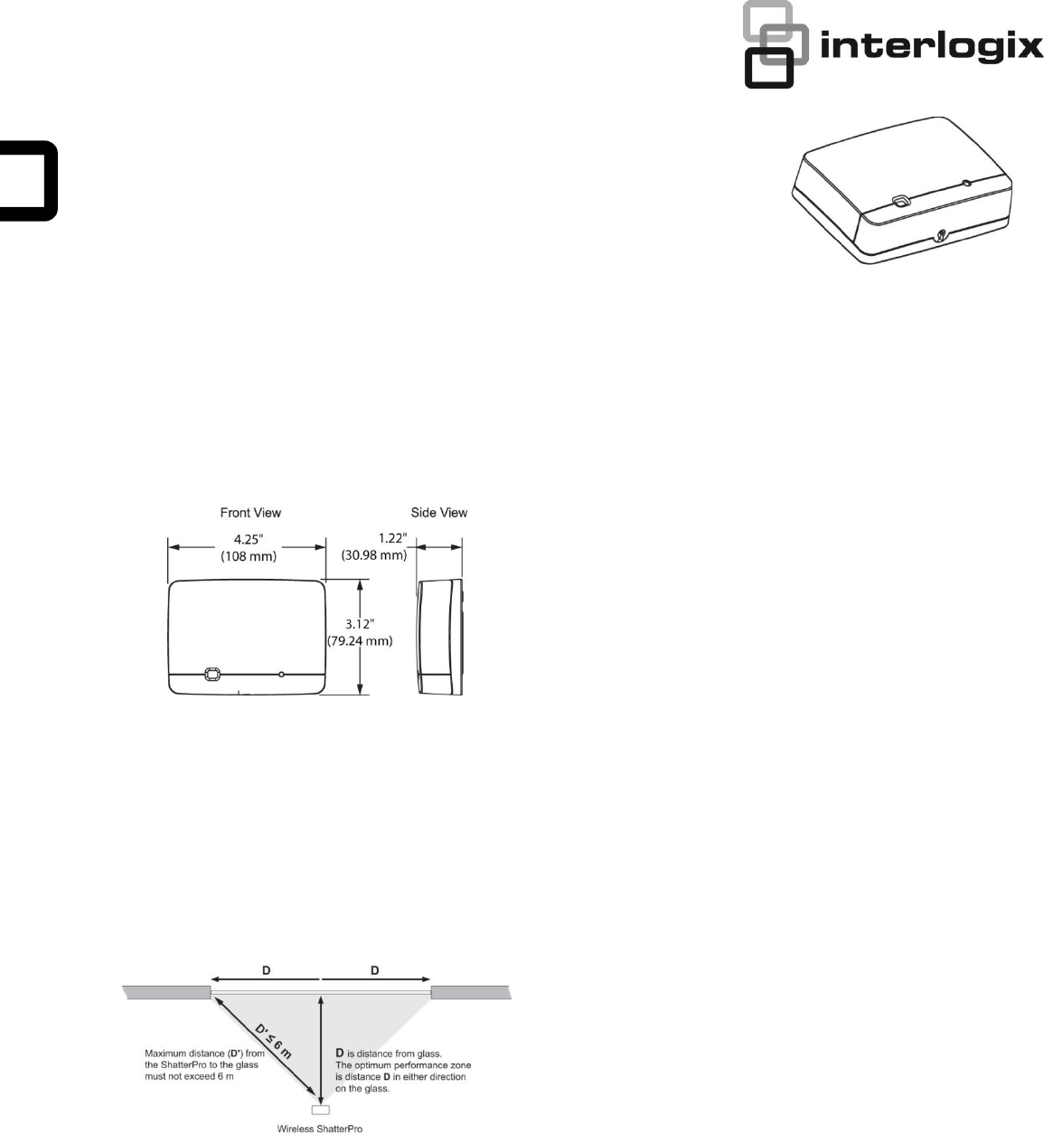
Figure 1: ShatterPro Glassbreak Sensor
The maximum detection range is 20' (6 m) for plate,
tempered, laminated and wired glass. For armor-coated
glass, the maximum detection range is 12' (3.65 m).
Coverage is measured from the sensor to the point on the
glass farthest from the sensor (see D and D' in Figure 2
below). See Specifications on page 4 for recommended
glass thickness.
Figure 2: Optimum Performance Zone
Note: ShatterPro may not consistently detect cracks in
glass, or bullets that break through the glass.
Glassbreak sensors should always be backed up by
interior protection.
Installation Guidelines
For best detection, avoid installing in rooms with lined,
insulating, or sound deadening drapes or rooms with closed
wooden window shutters inside.
Do not use sensor near air compressors. A blast of
compressed air may cause a false alarm.
Avoid stairwells, glass booths, and all rooms smaller
than 10' x 10' (3 m x 3 m).
The Pattern Recognition Technology™ of the
ShatterPro ignores most false alarm sounds. Some
sounds can duplicate the glass break pattern the
ShatterPro detects, however, so the ShatterPro works
best in rooms with only moderate noise. Avoid rooms
where white noise, such as a fan, is present. Avoid
rooms with noisy areas or multiple noise sources such
as small kitchens or bathrooms, garages, etc.
Note: For glass break protection in these applications
(where ShatterPro is not appropriate), use shock
sensors on the windows or window frames.
Avoid adding (learning) the sensor into 24-hour sensor
groups, where the sensor will be armed even when the
room is in use. Like a motion detector, a glass break
sensor may be tripped when occupants are in the
protected area. Adding the ShatterPro to a perimeter
sensor group, which is armed only when the perimeter
doors and windows are armed, will help prevent false
alarms.
The device may not work properly in humid rooms. Do
not install it in such conditions.
Tools needed
Phillips screwdriver
A 5709C-W hand-held tester
Note: Please see page 6 for important product safety,
warranty, limitation of liability, and disclaimer
information.
2 / 6 P/N 466-5401 • REV B • 9MAY18
Installation
Use the following procedure to install the ShatterPro.
1. Choose a mounting location. Since the sound of
breaking glass travels straight out from the broken
window, the best location for mounting the sensor is the
wall opposite the window--assuming the glass to be
protected is within the sensor range and line of sight.
The ceiling and adjoining (side) walls are also good
sensor locations. A ceiling mounted sensor will have
better detection if located 6' - 10' (2 m - 3 m) back from
the glass rather than directly above the glass.
IMPORTANT: DO NOT EXCEED THE 20' MAXIMUM
DETECTION RANGE OF THE
SHATTERPRO. While the sensor may
function beyond the 20' range it could miss a
minimum output glassbreak. Furthermore,
changing conditions in the room, such as
rearranging furniture, could reduce the range
of the sensor back to 20'.
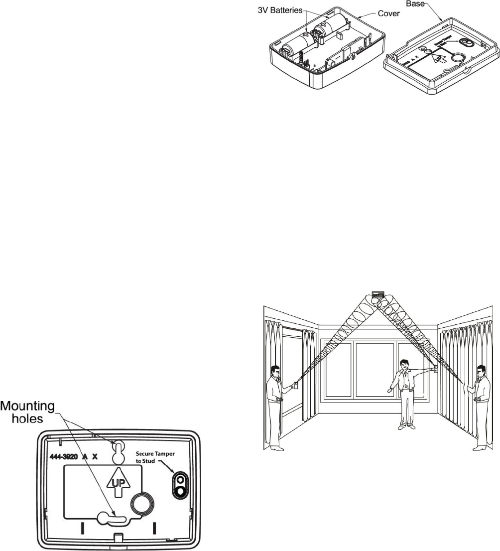
2. Remove the cover from the ShatterPro base. Hold the
base against the wall or ceiling at the desired mounting
location. Insert screws through the two mounting holes
in the base to attach it to the mounting surface.
Caution: You must be free of static electricity before
handling the transmitter circuit board. Touch a
grounded, bare metal surface before touching the
circuit board, or wear a grounding strap.
Figure 3: Mounting holes (back view of ShatterPro)
3. Insert two 3 V batteries as shown in Figure 4 and
replace the cover.
4. Use the procedures in the following sections; “Testing
the ShatterPro” and “Testing the System” on page 3 to
make sure the sensor is working properly with the panel.
Figure 4: Battery Installation
Testing the ShatterPro
Pattern Recognition Technology™ of the ShatterPro ignores
most false alarm sounds, including glassbreak testers, so
the ShatterPro must be set to “test mode” during the
following procedure (see step 2). When the sensor is in test
mode, processing of the glassbreak pattern in the upper and
lower frequencies is disabled. The ShatterPro is then
listening only for the mid-range frequencies, which the tester
reproduces. It is these frequencies that determine the sensor
detection range.
Figure 5: Testing the ShatterPro
The ShatterPro is designed to detect the breaking of framed
glass mounted in an outside wall. Testing the sensor with
unframed glass, such as broken bottles etc. may not trip the
sensor. Use the hand-held tester and the following
procedure to test the ShatterPro.
1. Set the tester to “tempered glass.”
The hand-held tester has a different setting for each
type of glass. You should always set the tester for
tempered or laminated glass (either is correct and both
have the same range) unless you are certain that all the
glass to be protected is plate glass.
P/N 466-5401 • REV B • 9MAY18 3 / 6
2. Hold the tester speaker directly on top of the sensor and
activate the tester. The sensor will alarm; then it will go
into test mode for one minute. While in the test mode,
the LED on the sensor will blink continuously.
Extend the test mode time by activating the tester at
least once a minute.
3. Holding the tester near the surface of the glass and
behind any closed drapes or blinds, aim the tester at the
ShatterPro and hold down the test button (see Figure 5:
Testing the ShatterPro on page 2).
Remember, the ShatterPro should not be installed in
rooms with lined, insulating, or sound deadening drapes
or rooms with closed wooden window shutters inside.
4. Observe the LED on the sensor. If the sensor is
detecting the tester signal, the LED will remain on but
will stop blinking momentarily. This indicates the sensor
is mounted within range and is working properly.
If the sensor LED blinks continuously when the test
button is pressed, the sensor is not detecting the tester
signal. Replace the tester battery if you suspect it is not
producing a strong signal. If you are certain that the
tester signal is strong, reposition the sensor closer to
the window and retest. Add more sensors if necessary
to achieve complete coverage.
5. The sensor will automatically exit test mode if it does not
sense any signals for 1 minute.
The “Hand Clap” Test
You can test the ShatterPro without enabling the test mode
by clapping your hands loudly under the sensor. This sound
will not trip the alarm, but the sensor LED will blink twice.
This is a signal that the sensor has power and that the
microphone and circuit board are functioning.
Adding the ShatterPro to Panel Memory
The following procedure is a general guideline for adding
(learning) the sensor into panel memory. Refer to your panel
installation instructions or reference manual for complete
details.
1. Set the panel to Program mode.
2. Proceed to the LEARN SENSORS menu.
3. Select the appropriate sensor group and sensor
number.
4. Trip the tamper switch on the sensor.
5. Repeat the above steps until all sensors are added
(learned) into the panel.
6. Exit Program mode.
Testing the System
The following steps describe general guidelines for testing
the sensor. Refer to your panel installation instructions or
reference manual for complete details.
1. Set the panel to the Dealer Sensor Test mode.
2. Use the hand-held tester to trip the sensor.
3. Listen for status beeps (or a voice message) to indicate
that the panel is receiving transmissions from the sensor
OR
Look for a message on the touchpad display.
Note: Refer to your panel installation instructions for
troubleshooting information.

4 / 6 P/N 466-5401 • REV B • 9MAY18
Specifications
Feature
Description
Compatibility
All 319.5 MHz Learn Mode™ panels; All Caddx 319.5 MHz panels
Dimensions
4.25" (108 mm) length
3.12" (79.24 mm) width
1.22" (30.98 mm) depth
Operational voltage
2.6 to 4.5 VDC
Current draw
26 A typical average
Battery life
5 years average
Batteries
(2) Duracell DL 123A 3V Lithium
Transmitter
Frequency
319.5 MHz
Transmitter
Conditions
Alarm, Tamper, Low Battery Supervisory
Microphone
Omnidirectional electret
Operating
Temperature Range
32° to 120°F (0° to 50°C)
Storage
Temperature Range
-30° to 140°F (-34° to 60°C)
Max. Humidity
90% Relative Humidity (non-condensing)
Recommended
glass Size
Minimum 1' x 2' (0.3 m x 0.6 m) or larger
Glass thickness
Plate: 3/32" to ¼" (2.4 mm to 6.4 mm)
Tempered: ⅛" to ¼" (3.2 mm to 6.4 mm)
Wired: ¼" (6.4 mm)
Laminated: ⅛" to ¼" (3.2 mm to 6.4 mm)

P/N 466-5401 • REV B • 9MAY18 5 / 6
Regulatory Information
Manufacturer
UTC Fire & Security Americas Corporation Inc Blvd Eje 1 Y Eje C, Parque Ind CARR INT NAVOJOA-LOS MOCHIS
KM 8.5 85895 Navojoa SON MEXICO
FCC / IC
compliance
This device complies with part 15 of the FCC Rules. Operation is subject to the following two conditions: (1) This
device may not cause harmful interference, and (2) this device must accept any interference received, including
interference that may cause undesired operation.
This equipment generates, uses, and can radiate radio frequency energy and, if not installed and used in accordance
with the instructions, may cause harmful interference to radio communications. However, there is no guarantee that
interference will not occur in a particular installation.
If this equipment does cause harmful interference to radio or television reception, which can be determined by turning
the equipment off and on, the user is encouraged to try to correct the interference by one or more of the following
measures:
• Reorient or relocate the receiving antenna.
• Increase the separation between the equipment and receiver.
• Connect the equipment into an outlet on a circuit different from that to which the receiver is connected.
• Consult the dealer or an experienced radio/TV technician for help.
Changes or modifications not expressly approved by UTC Fire and Security could void the user’s authority to operate
the equipment.
This device complies with Industry Canada license-exempt RSS standard(s). Operation is subject to the following two
conditions: (1) this device may not cause interference, and (2) this device must accept any interference, including
interference that may cause undesired operation of the device.
Cet appareil est conforme avec Industrie Canada exempts de licence standard RSS (s). Son fonctionnement est
soumis aux deux conditions suivantes: (1) cet appareil ne doit pas provoquer d'interférences et (2) cet appareil doit
accepter toute interférence, y compris celles pouvant causer un mauvais fonctionnement de l'appareil.
In accordance with FCC requirements of human exposure to radiofrequency fields, the radiating element shall be
installed such that a minimum separation distance of 20 cm is maintained from the general population.
FCC: B4Z-799E5-SOUND
IC: 1175C-799E5SND
This Class B digital apparatus complies with Canadian ICES-003.
Cet appareil numérique de la classe B est conforme à la norme NMB-003 du Canada.
LIMITATION OF
LIABILITY
MAY ONLY REDUCE THE RISK OF EVENTS SUCH AS BREAK-INS, BURGLARY, ROBBERY OR FIRE; IT IS NOT
INSURANCE OR A GUARANTEE THAT SUCH EVENTS WILL NOT OCCUR, THAT ADEQUATE WARNING OR
PROTECTION WILL BE PROVIDED, OR THAT THERE WILL BE NO DEATH, PERSONAL INJURY, AND/OR
PROPERTY DAMAGE AS A RESULT.
WHILE INTERLOGIX UNDERTAKES TO REDUCE THE PROBABILITY THAT A THIRD PARTY MAY HACK,
COMPROMISE OR CIRCUMVENT ITS SECURITY PRODUCTS OR RELATED SOFTWARE, ANY SECURITY
PRODUCT OR SOFTWARE MANUFACTURED, SOLD OR LICENSED BY INTERLOGIX, MAY STILL BE HACKED,
COMPROMISED AND/OR CIRCUMVENTED.
INTERLOGIX DOES NOT ENCRYPT COMMUNICATIONS BETWEEN ITS ALARM OR SECURITY PANELS AND
THEIR OUTPUTS/INPUTS INCLUDING, BUT NOT LIMITED TO, SENSORS OR DETECTORS UNLESS REQUIRED
BY APPLICABLE LAW. AS A RESULT THESE COMMUNICATIONS MAY BE INTERCEPTED AND COULD BE
USED TO CIRCUMVENT YOUR ALARM/SECURITY SYSTEM.

6 / 6 P/N 466-5401 • REV B • 9MAY18
WARRANTY
DISCLAIMERS
INTERLOGIX HEREBY DISCLAIMS ALL WARRANTIES AND REPRESENTATIONS, WHETHER EXPRESS,
IMPLIED, STATUTORY OR OTHERWISE INCLUDING (BUT NOT LIMITED TO) ANY WARRANTIES OF
MERCHANTABILITY OR FITNESS FOR A PARTICULAR PURPOSE WITH RESPECT TO ITS SECURITY
PRODUCTS AND RELATED SOFTWARE. INTERLOGIX FURTHER DISCLAIMS ANY OTHER IMPLIED WARRANTY
UNDER THE UNIFORM COMPUTER INFORMATION TRANSACTIONS ACT OR SIMILAR LAW AS ENACTED BY
ANY STATE.
(USA ONLY) SOME STATES DO NOT ALLOW THE EXCLUSION OF IMPLIED WARRANTIES, SO THE ABOVE
EXCLUSION MAY NOT APPLY TO YOU. THIS WARRANTY GIVES YOU SPECIFIC LEGAL RIGHTS AND YOU MAY
ALSO HAVE OTHER LEGAL RIGHTS THAT VARY FROM STATE TO STATE.
INTERLOGIX MAKES NO REPRESENTATION, WARRANTY, COVENANT OR PROMISE THAT ITS SECURITY
PRODUCTS AND/OR RELATED SOFTWARE (I) WILL NOT BE HACKED, COMPROMISED AND/OR
CIRCUMVENTED; (II) WILL PREVENT, OR PROVIDE ADEQUATE WARNING OR PROTECTION FROM BREAK-
INS, BURGLARY, ROBBERY, FIRE; OR (III) WILL WORK PROPERLY IN ALL ENVIRONMENTS AND
APPLICATIONS.
DISCLAIMER
THE INFORMATION IN THIS DOCUMENT IS SUBJECT TO CHANGE WITHOUT NOTICE. UTC ASSUMES NO
RESPONSIBILITY FOR INACCURACIES OR OMISSIONS AND SPECIFICALLY DISCLAIMS ANY LIABILITIES,
LOSSES, OR RISKS, PERSONAL OR OTHERWISE, INCURRED AS A CONSEQUENCE, DIRECTLY OR
INDIRECTLY, OF THE USE OR APPLICATION OF ANY OF THE CONTENTS OF THIS DOCUMENT. FOR THE
LATEST DOCUMENTATION, CONTACT YOUR LOCAL SUPPLIER OR VISIT US ONLINE AT
WWW.INTERLOGIX.COM.
THIS PUBLICATION MAY CONTAIN EXAMPLES OF SCREEN CAPTURES AND REPORTS USED IN DAILY
OPERATIONS. EXAMPLES MAY INCLUDE FICTITIOUS NAMES OF INDIVIDUALS AND COMPANIES. ANY
SIMILARITY TO NAMES AND ADDRESSES OF ACTUAL BUSINESSES OR PERSONS IS ENTIRELY
COINCIDENTAL.
INTENDED USE
USE THIS PRODUCT ONLY FOR THE PURPOSE IT WAS DESIGNED FOR; REFER TO THE DATA SHEET AND
USER DOCUMENTATION. FOR THE LATEST PRODUCT INFORMATION, CONTACT YOUR LOCAL SUPPLIER OR
VISIT US ONLINE AT WWW.INTERLOGIX.COM.
THE SYSTEM SHOULD BE CHECKED BY A QUALIFIED TECHNICIAN AT LEAST EVERY 3 YEARS AND THE
BACKUP BATTERY REPLACED AS REQUIRED.
ADDITIONAL PRODUCT WARNINGS AND DISCLAIMERS ARE LOCATED AT
https://www.utcfssecurityproducts.eu/productwarning/.
Contact information
www.utcfireandsecurity.com or www.interlogix.com
For customer support, see www.interlogix.com/customer-support
© 2018 UTC Fire & Security Americas Corporation, Inc.
Interlogix is part of UTC Climate Controls & Security, a unit
of United Technologies Corporation. All rights reserved.
April 24, 2018