UTC Fire and Security Americas 802A-SHOCK Shock Sensor User Manual Learn Mode Shock Sensor Installation Instructions
UTC Fire & Security Americas Corporation, Inc. Shock Sensor Learn Mode Shock Sensor Installation Instructions
Contents
- 1. User Manual
- 2. 466-1925-b-60-886-Shock-Sensor-Installs-14-8-2018
- 3. 466-1925-c-60-886-Shock-Sensor-Installs-29-10-2018
466-1925-b-60-886-Shock-Sensor-Installs-14-8-2018
P/N 466-1925 • REV B • 14AUG18 1
Learn Mode Shock Sensor Installation
Instructions
Product Summary
The Learn Mode Shock Sensor has the following main
functions:
To detect the vibrations made by an intruder trying to
break a window or door.
To detect a window or door opening.
To detect tamper situations, such as an intruder removing
the sensor cover.
Vibrations cause a momentary open circuit in the shock
element of the sensor. The circuit closes again when the
vibration stops. The sensor microcontroller “sees” the
open/close action as a pulse, causing the sensor to transmit an
alarm signal. The sensor has two different detection modes:
Gross Attack: Detect a violent blow sufficient in length to
trip sensor.
Pulse Count: Detect a sufficient number of less violent
blows (rapping or tapping).
The sensor includes an internal magnetic reed switch that must
be disabled if it is not used.
A cover tamper provides additional security if an intruder tries
to disable or damage the sensor.
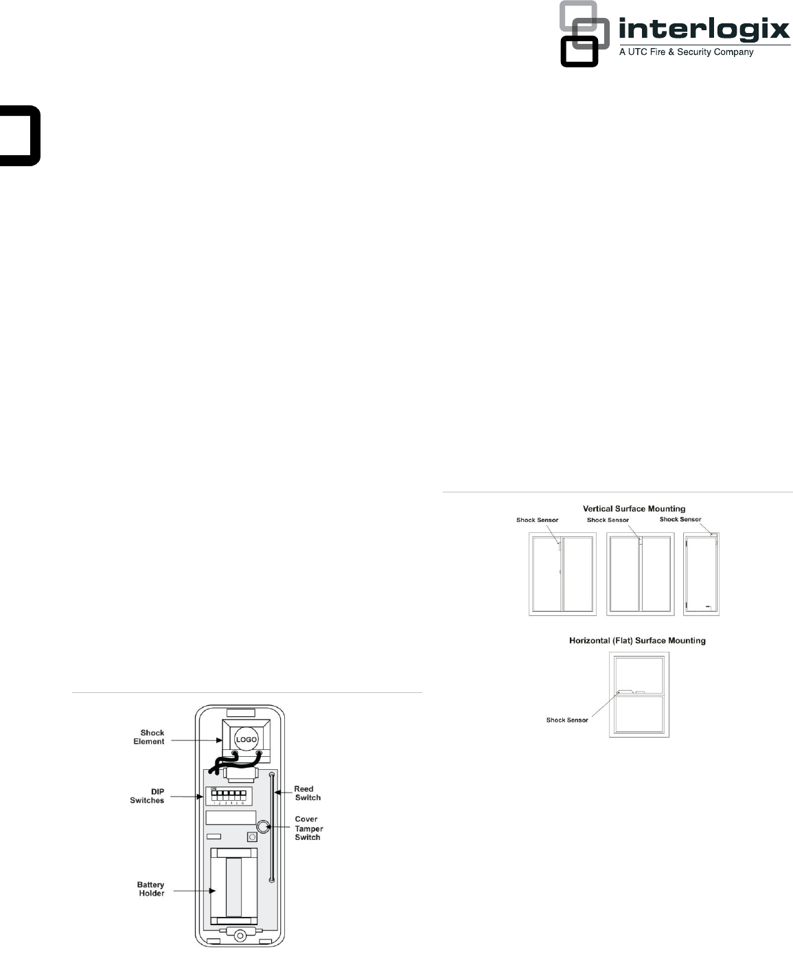
Figure 1: Shock sensor main components
Installation Guidelines
Learn the sensor before adjusting the shock sensitivity.
The sensor is shipped with the reed switch enabled and
open, and this is how it must be learned.
Before permanently mounting the sensor, test it at the
intended location to make sure that the panel can receive
sensor signal transmissions. The sensor is an RF device
and there may be blind or non-operational locations within
the installation. Normally, these can be overcome by
moving the sensor or receiver.
Always mount the shock sensor so that the detector is on
the frame and not on glass, solid, or hollow-core doors.
See Figure 2 below for mounting locations.
Figure 2: Mounting options for door/window styles
Mount the sensor in a location where the structure can
transmit vibrations to the sensor.
The sensor can be mounted on a vertical surface or on a
horizontal (flat) surface.
Make sure the window fits snugly in the frame and doesn’t
move or rattle.
Hold the sensor against the frame to make sure the
sensor base fits on the surface area of the frame and
doesn’t extend over the surface edges.
2 Learn Mode Shock Sensor Installation Instructions
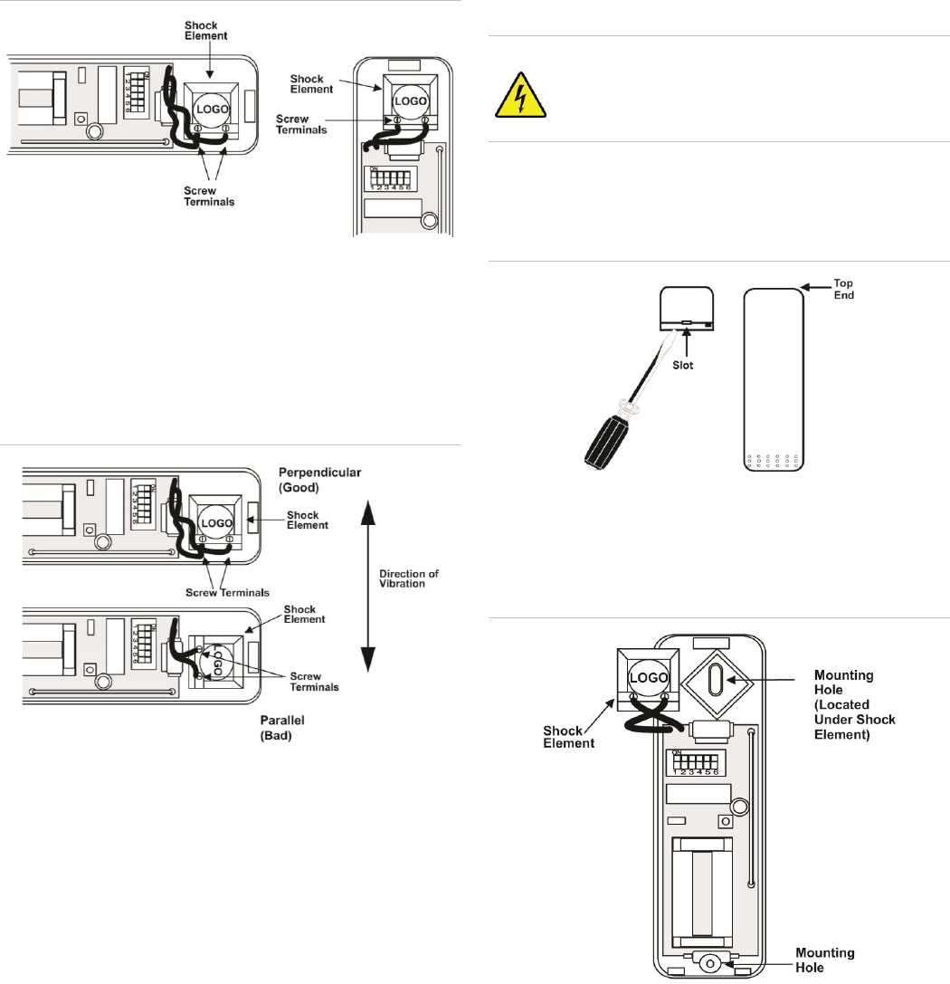
Shock Sensor Orientation
There are two types of shock sensor mounting orientations; on
a vertical surface or on a horizontal surface (sill or ledge).
On a vertical surface, there are two orientations (see Figure 3
below).
Note: On a vertical surface, the shock sensor element must always
be oriented with its screw terminals down, or the writing on the
shock element horizontal.
Figure 3: Mounting on a vertical surface
On a horizontal surface (sill or ledge), any orientation is
allowed, but certain sensor element orientations are better than
others. The element is much better at detecting horizontal
vibrations perpendicular to its writing than parallel (see
Figure 4 below).
Figure 4: Mounting on horizontal surface
Tools and Supplies
Control panel installation instructions
Phillips screwdriver
Slotted screwdriver (to pry off the cover)
Two #6 x ¾" flathead screws for mounting the sensor
(included)
Two #6 x ⅝" screws for mounting the magnet (included)
Installation
Caution: When handling electronic components, the user
must be free of static electricity. Touch a grounded,
bare metal surface before touching a circuit board
or wear a grounded wrist strap.
1. Insert a slotted screwdriver into the slot at the top end of
the unit and remove the cover (see Figure 5 below).
Figure 5: Remove the sensor cover
2. Using the flathead mounting screws, secure the base to
the mounting surface either vertically or horizontally as
required (see Figure 6 below).
Figure 6: Sensor base mounting holes
Learn Mode Shock Sensor Installation Instructions 3
3. Position the shock element and press it firmly into its
socket (see Figure 7 below).
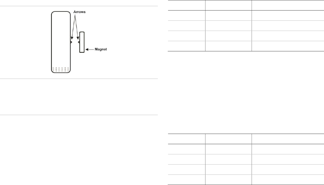
4. If using the reed switch, use the two remaining screws to
mount the magnet so that its arrow is aligned with the
arrow on the sensor case (see Figure 7 below).
Figure 7: Magnet alignment
IMPORTANT!: If the reed switch is not being used; must
disabled. If the reed switch is enabled but no
magnet is installed, the sensor will be in a
continuous alarm state.
Adjusting the Shock Sensor
DIP switches
The following describes the DIP switch functions:
DIP Switches 1 and 2: Adjust the Pulse Count.
DIP Switches 3 and 4: Adjust the sensitivity setting of
Gross Attack detection.
DIP Switch 5: Enable/disable reed switch.
DIP Switch 6: Not used.
Note: In order for the LED to indicate shock detection while adjusting
the sensitivity, be sure the reed switch is disabled (DIP switch 5
OFF) or that the magnet is lined up with the reed switch if DIP
switch 5 is ON.
Gross Attach Adjustment
1. To adjust the sensor for Gross Attack, set DIP switches 1
and 2 to the ON position. This disables the Pulse Count so
that the unit can only be activated by a Gross Attack.
2. Apply high level shocks to the mounting structure, using
the LED as a guide to when the alarm trips (LED on for 4
seconds). The LED will blink for 1 second every time the
sensor detects a pulse. A shock that is severe enough to
cause an alarm will cause the LED to light for
approximately 4 seconds.
3. Use switches 3 and 4 to adjust the Gross Attack sensitivity
of the sensor (see Table 1 below).
4. Repeat step 2 each time a sensitivity change has been
made.
Table 1: Gross attach sensitivity settings
DIP Switch 3
DIP Switch 4
Sensitivity
OFF
OFF
1 (maximum sensitivity)
ON
OFF
2
OFF
ON
3
ON
ON
4 (minimum sensitivity)
Pulse Count Adjustment
1. Set the sensor to the desired Pulse Count (see Table 2
below).
Note: Pulse Count Signals are counted at 1-second intervals and
stored in a 30-second digital memory. These small signals can
detect an intruder gently prying open a window or door frame.
Table 2: Pulse count adjustment
DIP Switch 1
DIP Switch 2
Adjustment
OFF
OFF
4
ON
OFF
6
OFF
ON
8
ON
ON
Disabled
2. To test the pulse count setting, generate small shocks on
the mounting structure. Each time a shock is detected, a
pulse is registered in memory and the LED will blink for
one second. If the programmed pulse count is reached
within the most recent 30 seconds, the alarm will trip and
the LED will light for approximately 4 seconds. If the alarm
trips for any reason, the stored pulses are cancelled.
3. Use switches 1 and 2 to adjust the Pulse Count.
4. Repeat step 2 each time a sensitivity change is made.
Reed Switch Setting
After adjusting the sensor sensitivity, set DIP switch 5 to the
appropriate setting, ON for enabled or OFF for disabled.

4 Learn Mode Shock Sensor Installation Instructions
System Programming
This section describes the basic steps for adding the sensor to
panel memory. Refer to the specific panel documentation for
complete programming details. The reed switch must be
enabled and open when learning the sensor.
1. With the cover on the sensor, set the panel to Program
mode.
2. Proceed to the Learn Sensors menu.
3. Select the appropriate sensor group and sensor number
assignments.
4. When prompted by the panel to trip the sensor, remove
the sensor cover to activate the tamper switch.
5. Exit Program mode.
RF Testing
This section describes the basic steps for testing the sensor.
Refer to the specific panel or receiver documentation for
complete testing details.
1. Set the panel to Sensor Test.
2. Trip the sensor.
3. Listen for appropriate response from system sirens.
4. Exit Sensor Test.
Battery Replacement
When the system indicates that the sensor has a low battery,
remove the old battery and install a new battery (Duracell
DL123A or a Sanyo CR123A) into the battery holder, observing
proper polarity.
Caution: Replace only with Duracell DL123A battery or a
Sanyo CR123A battery. Observe polarity when
installing a new battery. Installing the battery
backwards may cause damage to the sensor.
Dispose of used batteries according to the
manufacturer’s instructions and/or local government
authorities.
Specifications
Compatibility
All 319.5 MHz Learn Mode
Panels/Receivers
Dimensions (W x L x H)
1.4 x 6.0 x 1.25 in. (3.5 x 15.2 x 3.2 cm)
Operating temperature
32 to 122°F (0 to 50°C)
Storage temperature
-29 to 140°F (-34 to 60°C)
Humidity
90% relative humidity non-condensing
Battery
Duracell DL123A or Sanyo CR123A 3V
Lithium (part number 34-030)
Transmitter frequency
319.5 MHz
Transmitter range
500 ft. open air
Regulatory Information
Manufacturer
UTC Fire & Security Americas Corporation, Inc.
2955 Red Hill Ave Suite 100, Costa Mesa, CA
92626, USA
FCC compliance
This device complies with part 15 of the FCC
Rules. Operation is subject to the following two
conditions: (1) This device may not cause harmful
interference, and (2) this device must accept any
interference received, including interference that
may cause undesired operation.
Changes or modifications not expressly approved
by Interlogix can void the user’s authority to
operate the equipment.
FCC ID: B4Z-802A-SHOCK
IC ID: 1175C-802ASHOCK
2002/96/EC (WEEE directive): Products marked
with this symbol cannot be disposed of as
unsorted municipal waste in the European Union.
For proper recycling, return this product to your
local supplier upon the purchase of equivalent
new equipment, or dispose of it at designated
collection points. For more information see:
www.recyclethis.info.
