UTC Fire and Security Americas 808-UFT Universal Fire Transmitter User Manual
UTC Fire & Security Americas Corporation, Inc. Universal Fire Transmitter
User Manual
1
8QLYHUVDO)LUH
7UDQVPLWWHU8)7
ITI Part No. 60-917
Installation Instructions
Document Number: 466-1940 Rev. A PRELIMINARY
January 2002
P
re
li
m
i
nary
1/22/02
About this Document
This document describes how to install, program and test
the Universal Fire Transmitter (UFT).
Product Summary
The Universal Fire Transmitter is a supervised, battery
powered transmitter designed to be connected to externally
wired fire detection equipment. The transmitter reports sig-
nals from the fire detection equipment to the panel via wire-
less signals.
The UFT sends supervision transitions to the panel approxi-
mately every 64 minutes. An 4.7k Ohm end-of-line resistor
must be installed between the UFT and the fire detection
equipment for proper supervision of the UFT.
The UFT is equipped with a cover tamper and a reed switch
designed to provide wall tamper protection.
Note The 3.6-volt lithium battery cannot be replaced by
installers or users. If you receive a low battery report, you
must return the sensor to Interlogix for replacement.
Tools Needed
❑#6 flathead screws or 18-gauge brads
❑Screwdriver or brad driver
❑Small wire cutters
❑5/8” drill bit
❑13/16” drill bit (if mounted flush to a wall in a box)
❑Tape measure or ruler
❑pencil, pen or piece of chalk
Installation
The Universal Fire Transmitter can be installed on a wall or
in a non-metallic electrical box.
General Sensor Installation Guidelines
❑Keep all sensors within 200-300 feet of the nearest
transceiver module.
❑Mount sensors with screws or brads, not double-stick
tape.
❑Place sensors at least 5 inches above the floor to avoid
damaging them.
❑Use spacers (not included) to keep sensors and magnets
away from metal or metallic surfaces such as foil wall-
paper.
❑Avoid mounting sensors in areas with a large quantity
of metal or electrical wiring, such as a furnace or utility
room.
❑Avoid mounting sensors in areas where they will be
exposed to moisture.
❑Avoid mounting sensors in locations where the operat-
ing temperature (10° to 120° F) will be exceeded.
Do not remove the jumper from the sensor circuit
board! The sensor cannot work without the jumper.
Install on a Wall
1. Determine a suitable location for the UFT.
2. Mark where the magnet will be installed.
3. Drill a 3/4” diameter hole 3/4” deep into the wall.
4. Push the magnet into the hole, magnet side first.
5. Remove the UFT cover by squeezing the cover ends
firmly to release the tab on the cover from the slot on
the UFT base.
6. Remove the circuit board from the UFT base by pulling
back the plastic tab and lifting the battery to release the
circuit board.
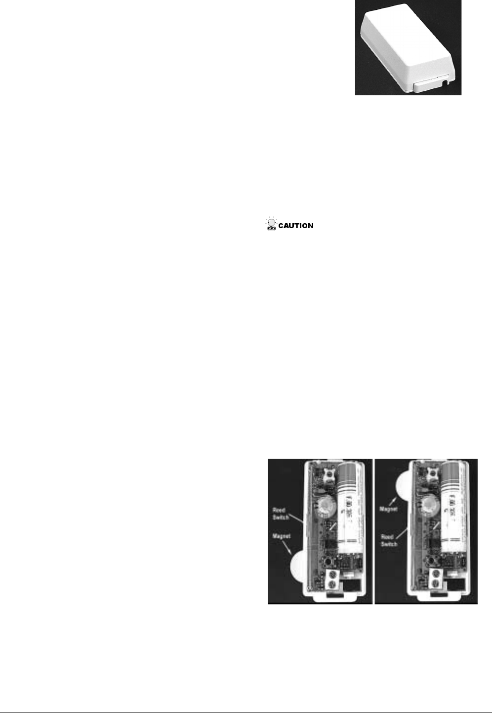
7. Mark where the UFT will be installed over the magnet.
See Figure 1 for acceptable magnet locations for a wall
mounted UFT.
Figure 1. Acceptable magnet locations for a wall
mounted UFT.
8. Verify the UFT reed switch is properly aligned with the
installed magnet.
9. Mount the UFT base with screws or brads. Use spacers
to compensate for metal surfaces or height variations.
2
Preliminary 1/22/02
10. Reattach the circuit board to the UFT base
11. Attach the External Switch (See “Connecting External
Switch” in this manual)
12. Reattach the UFT cover to the UFT base.
Install in an Electrical Box
Use a 4”x4” non-metallic electrical box that is at least 1½”
deep.
Mounting the box on a wall
In this installation method the UFT is mounted in an electri-
cal box attached to a wall. The magnet is installed in the
wall and passes through the box.
1. Determine a suitable location for the UFT.
2. Mark where the magnet will be installed.
3. Drill a 3/4” diameter hole 3/4” deep into the stud or
wall.
4. Mark where the box will be installed over the magnet.
5. Mark the box at the location where the magnet will
enter the box.
6. Drill a 13/16” hole in the box at the magnet location.
7. Mark where the UFT will be installed on the box.
8. Verify the UFT reed switch is properly aligned with the
magnet hole.
9. Mount the box using screws or brads making sure to
align the hole in the box with the hole in the wall or
stud.
10. Push the magnet, magnet side first, through the hole in
the box and into the hole in the stud or wall. The top of
the magnet should be flush with the side of the box.
11. Mount the UFT in the box using velcro strips.
12. Remove the UFT cover by squeezing the cover ends
firmly to release the tab on the cover from the slot on
the UFT base.
13. Attach the External Switch (See “Connecting External
Switch” in this manual)
14. Reattach the UFT cover to the UFT base.
Mounting the box in a wall
In this installation method the UFT is mounted in an electri-
cal box permanently installed in a wall. The magnet is
installed in the box.
1. Determine a suitable location for the UFT.
2. Mark the box at the location where the magnet will be
installed.
3. Drill a 3/4” hole in the box at the magnet location.
4. Insert the magnet into the hole.
5. Mark where the UFT will be installed on the box
6. Verify the UFT reed switch is properly aligned with the
magnet.
7. Mount the box in the wall using screws or brads.
8. Mount the UFT in the box using velcro strips.
9. Remove the UFT cover by squeezing the cover ends
firmly to release the tab on the cover from the slot on
the UFT base.
10. Attach the External Switch (See “Connecting External
Switch” in this manual)
11. Reattach the UFT cover to the UFT base.
Connecting External Switch
The normally open UFT (60-917) should be connected to a
normally open external switch.
Connection Guidelines
❑Do not use mechanical switches.
❑Do not use more than 100feet of 18-gauge, stranded or
solid core wire in any wire run.
❑Do not use more than 6 feet of untwisted wire in any
wire run.
❑Do not run wires parallel to electrical wires. If you
can’t avoid a parallel wire run, keep at least 18 inches
away from electrical wiring.
Note If necessary, you may cross electrical wires at a 90
degree angle.
Making the Connection
1. Make the connection to the external fire detection
device. (See your device’s instructions.)
Important ! A 4.7 k Ohm EOL resistor must be installed
at the fire detection device for proper supervision of the
UFT.
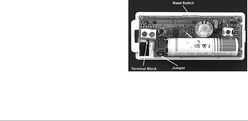
2. Feed the wire through the hole in the bottom of the
UFT.
3. Attach the wire to the terminal block. See Figure 2.
Note It may be beneficial to feed the wire through the
hole before mounting the UFT.
Figure 2. UFT component locations.
Programming
The following steps describe the general guidelines for pro-
gramming (learning) a sensor. Refer to the specific panel

3
Preliminary 1/22/02
instructions or reference manual for complete programming
details.
1. Set the panel to program mode.
2. Proceed to the LEARN SENSORS menu.
3. Select the appropriate zone type and zone number
assignments.
4. Set the external switch in the alarm condition (open for
a normally closed circuit, closed for a normally open
circuit).
5. Trip the sensors tamper switch by removing the sensor
cover.
6. Exit program mode.
7. Place the cover back on the sensor.
Testing
The following steps describe the general guidelines for test-
ing the sensor. Refer to the specific panel installation
instructions or reference manual and the instructions for the
external switch for complete testing details.
1. Set the panel to the installer zone test mode.
2. Trip the sensor.
3. The signal strength from the UFT will be displayed on
all keypads. It should be 15 or higher for proper opera-
tion.
Specifications
Operating Temperature
Range: ...........................10° to 120° F
Compatibility: ...............Advent Commercial Fire 250 Zone
(60-562-03)
Advent Commercial Fire 132 Zone
(60-562-06)
Advent Commercial Burg 250
Zone (60-562-01)
Advent Commercial Burg 132
Zone (60-562-04)
Power Source: ...............1 AA 3.6-volt lithium battery (not
replaceable)
Transmit Range:............At least 500 feet, open air

4
Preliminary 1/22/02
FCC Notice
FCC Part 15 Information to the User
Changes or modifications not expressly approved by Interlogix, Inc. can
void the user’s authority to operate the equipment.
FCC Part 15 Class A
This equipment has been tested and found to comply with the limits for
a class A digital device, pursuant to part 15 of the FCC rules. These
limits are designed to provide reasonable protection against harmful
interference when the equipment is operated in a commercial environ-
ment.
This equipment generates, uses, and can radiate radio frequency energy
and, if not installed and used in accordance with the instruction manual,
may cause harmful interference to radio communications. Operation of
this equipment in a residential area is likely to cause harmful interfer-
ence in which case users will be required to correct the interference at
their own expense.
FCC Part 15 Class B
This equipment has been tested and found to comply with the limits for
a Class B digital device, pursuant to part 15 of the FCC Rules. These
limits are designed to provide reasonable protection against interference
in a residential installation.
This equipment generates, uses, and can radiate radio frequency energy
and, if not installed and used in accordance with the instructions, may
cause harmful interference to radio communications. However, there is
no guarantee that interference will not occur in a particular installation.
If this equipment does cause harmful interference to radio or television
reception, which can be determined by turning the equipment off and
on, the user is encouraged to try to correct the interference by one or
more of the following measures:
❑Reorient or relocate the receiving antenna.
❑Increase the separation between the equipment and receiver.
❑Connect the affected equipment and the panel receiver to separate
outlets, on different branch circuits.
❑Consult the dealer or an experienced radio/TV technician for help.
FCC ID: B4Z-808-UFT
2266 Second Street North | North Saint Paul Mn | 55109 | 800-777-2624 | www.interlogixinc.com
©2001 Interlogix,™ Inc. Interlogix is a trademark of Interlogix, Inc. ITI, Advent, and SuperBus are registered trademarks of Interlogix, Inc.