UTC Fire and Security Americas 840B-SHK Shock Sensor User Manual
UTC Fire & Security Americas Corporation, Inc. Shock Sensor
Install and Users Manual
1
,QVWDOODWLRQ,QVWUXFWLRQV
*(,QWHUORJL[
'
PRELIMINARY 10/1/03
Product Summary
The Learn Mode Shock Sensor has the following three main
functions:
•To detect the vibrations made by an intruder trying to
break a window or door.
•To detect a window or door opening.
•To detect tamper situations, such as an intruder remov-
ing the sensor cover or the sensor from the wall.
Vibrations cause a momentary open circuit in the shock ele-
ment of the sensor. The circuit closes again when the vibra-
tion stops. The sensor microcontroller “sees” the open/close
action as a pulse, causing the sensor to transmit an alarm
signal. The sensor has two different detection modes:
•Gross Attack - detect a violent blow sufficient in length to
trip sensor.
•Pulse Count - detect a sufficient number of less violent
blows (rapping or tapping).
The sensor includes an internal magnetic reed switch that
must be disabled if it is not used.
Extend the battery life of the sensor by adding a second 3-
volt lithium battery.
Installation Guidelines
•Learn the sensor before adjusting the shock sensitivity.
The sensor is shipped with the reed switch enabled and
open, and this is how it must be learned.
•Before permanently mounting the sensor, test it at the
intended location to make sure that the panel can
receive sensor signal transmissions. The sensor is an
RF device and there may be blind or non-operational
locations within the installation. Normally, these can be
overcome by moving the sensor or receiver.
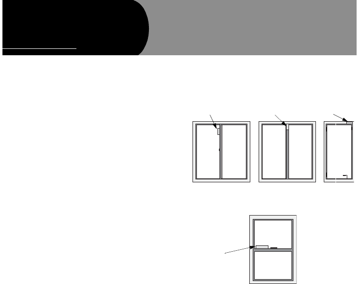
•Always mount the shock sensor so that the detector is on
the frame and not on the glass. See Figure 2 for mount-
ing locations.
•Mount the sensor in a location where the structure can
transmit vibrations to the sensor.
•The sensor can be mounted on a vertical surface or on a
horizontal (flat) surface.
•Make sure the window fits snugly in the frame and
doesn’t move or rattle.
•Hold the sensor against the frame to make sure the sen-
sor base fits on the surface area of the frame and doesn’t
extend over the surface edges.
Figure 1. Mounting Options for Door/Window Sensor
Tools and Supplies
•Control panel installation instructions
•Phillips screwdriver
•Slotted screwdriver (to pry off the cover)
•Two #6 x 2 cm flathead screws for mounting the sensor
(included)
•Two #6 x 1.5 cm screws for mounting the magnet
(included)
Vertical (Wall) Surface Mounting
Horizontal (Ledge) Surface Mounting
Shock Sensor Shock Sensor Shock Sensor
Shock Sensor
/HDUQ0RGH6KRFN6HQVRU
Document No. 466-2023 Rev. A
September 2003
2
PRELIMINARY 10/1/03
Installation
Caution!
You must be free of all static electricity when handling elec-
tronic components. Touch a grounded, bare metal surface
before touching a circuit board or wear a grounded wrist
strap.
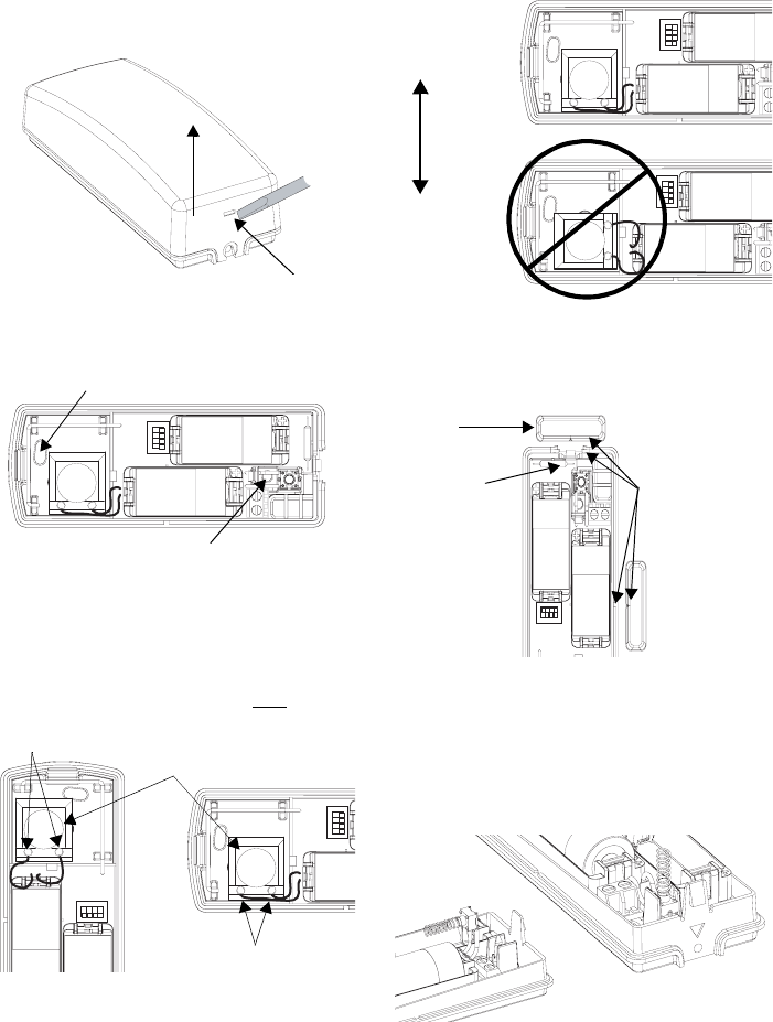
1. Insert a slotted screwdriver into the slot at the top end of
the unit and remove the cover by lifting it up (see
Figure 2).
Figure 2. Removing the Cover
2. Using the flathead mounting screws, secure the base to
the mounting surface either vertically or horizontally as
required (see Figure 3).
Figure 3. Sensor Mounting Holes
3. Position the shock element and press it firmly into its
socket.
Note
On a vertical surface, the shock sensor element must
always be oriented with its screw terminals down, or the
writing on the shock element horizontal.
Figure 4. Positioning the Shock Element According to
Mounting Orientation on a Vertical Surface
Note
On a horizontal surface (sill or ledge), any orientation is
allowed, but certain sensor element orientations are better
than others. The element is much better at detecting hori-
zontal vibrations perpendicular to its writing than it is parallel
vibrations (see Figure 5).
Figure 5. Positioning Shock Elements for Horizontal Sur-
face Mounting
4. If using the reed switch, use the two remaining screws to
mount the magnet so its arrow is aligned with the arrow
on the sensor case (see Figure 7).
Figure 6. Possible Magnet/Reed Switch Alignment
Important!
You must disable the reed switch using the dip
switches on the circuit board if you are not using it. If
the reed switch is enabled but no magnet is installed, the
sensor will be in a continuous alarm state. See the Sensor
Settings section for more information.
5. Install the tamper switch as shown (see Figure 7).
Figure 7. Installing the Tamper Switch
6. Install the 4.7 k Ohm EOL resistor across the terminals
of the external switch block.
1 2 3 4
ON
Mounting Hole
Mounting Hole
(Wall Tamper)
1 2 3 4
ON
1 2 3 4
ON
Shock Element
Screw Terminals
Screw Terminals
1 2 3 4
ON
1 2 3 4
ON
Perpendicular
CORRECT
INCORRECT
Direction of
Vibration
1 2 3 4
ON
Magnet
Alignment
Marks
Reed Switch
1
2

3
PRELIMINARY 10/1/03
Setting the Detection Mode
The shock sensor has two detection modes:
•Gross Attack - detects a violent blow sufficient in length
to trip sensor.
•Pulse Count - detects a sufficient number of less violent
blows (rapping or tapping).
Pulse Count signals are counted at 1-second intervals
and stored in a 30-second digital memory. These small
signals can detect an intruder gently prying open a win-
dow or door frame.
To set the shock sensor detection modes:
1. Hold in the tamper spring. Continue to hold in while mov-
ing the DIP switches to their desired settings.
2. Set the DIP switches to the desired pulse count (see
Table 1). The LED will start blinking once a DIP switch is
moved.
3. Set the DIP Switches to the desired Gross Attack sensi-
tivity (See Table 2).
4. Release the tamper spring. The LED will flash quickly 3
times to indicate the settings have been programmed.
5. Repeat steps 1-4 each time you make a sensitivity
change. It may then be necessary to reset the DIP
switches to their proper device settings (See Sensor Set-
tings).
Testing the Detection Modes
To test the Pulse Count setting:
•Generate small shocks on the mounting structure. Each
time a shock is detected, a pulse is registered in memory
and the LED will blink for one second. If the programmed
pulse count is reached within the most recent 30 sec-
onds, the alarm will trip and the LED will light for approx-
imately 4 seconds. If the alarm trips for any reason, the
stored pulses are cancelled.
To test the Gross Attack setting:
•Apply high level shocks to the mounting structure, using
the LED as a guide to when the alarm trips (LED on for 4
seconds).
The LED will blink for 1 second every time the sensor
detects a pulse. A shock that is severe enough to cause
an alarm will cause the LED to light for approximately 4
seconds.
Sensor Settings
After programming the Detection Mode, the DIP switches
are used to set up the sensors use of the reed switches
and/or external contacts. If the external contact is not used
the 4.7 k Ohm EOL resistor must be installed across the ter-
minals of the external switch block.
With the tamper spring in the up position, set the DIP
switches to the desired settings (See Table 3).
Important!
DO NOT remove the reed switches from the circuit board!
The Shock Sensor will not function properly. If you don’t
need to use the reed switches, disable them with the DIP
switches as described in Table 3.
System Programming
This section describes the basic steps for adding the sensor
to panel memory. Refer to the specific panel installation
instructions for complete programming details.
The reed switch must be enabled and open when learning
the sensor.
1. With the cover on the sensor, set the panel to Program
mode.
2. Proceed to the LEARN SENSORS menu.
3. Select the appropriate sensor group and sensor number
assignments.
4. When prompted by the panel to trip the sensor, remove
the sensor cover to activate the tamper switch.
5. Exit program mode.
RF Testing
This section describes the basic steps for testing the sen-
sor. Refer to the specific panel or receiver installation
instructions for complete testing details.
1. Set the panel to Sensor Test.
2. Trip the sensor.
3. Listen for appropriate response from system sirens.
4. Exit Sensor Test.
•Use an RF Sniffer to help diagnose sensor problems.
Table 1: Pulse Count Adjustment
DIP Switch 1 DIP Switch 2 30-second Pulse
Count
OFF OFF 4
ON OFF 6
OFF ON 8
ON ON Disabled
Table 2: Gross Attack Sensitivity Settings
DIP Switch 3 DIP Switch 4 Sensitivity
OFF OFF 1 (most sensitive)
ON OFF 2
OFF ON 3
ON ON 4 (least sensitive)
Table 3: Sensor Settings
Switch
Number OFF ON
1 Unused Unused
2 Disable Reed
Switches
Enable Reed
Switches
3 Disable External
Contact
Enable External
Contact
4 External Contact
is Normally Open
External Contact is
Normally Closed

4
PRELIMINARY 10/1/03
Battery Replacement
When the system indicates that the sensor has a low bat-
tery, remove the old battery and install a new battery (Dura-
cell DL123A or a Sanyo CR123A) into the battery holder,
observing proper polarity.
Caution!
Replace only with a Duracell DL123A battery or a Sanyo
CR123A battery. Observe polarity when installing a new
battery. Installing the battery backwards may cause damage
to the sensor.
Dispose of used batteries according to the manufacturer’s
instructions and/or local government authorities.
Specifications
Model No.: 60-975-95R and 60-975-11-95R
RF Frequency: 319.5 MHz
Compatibility: All GE Interlogix 319.5 MHz Control Panels and
Receivers
Battery Type: 3.0 VDC Lithium
Recommended Battery: GE CR123A
Typical Standby Current (µA): 10
Estimated Battery Life: 5 years (one battery); 10 years (two
batteries)
Typical RF Power Output (mW): 10
Operating Temperature Range (C°): 0 to 49
Storage Temperature Range (C°): -34 to 60
Relative Humidity: 0 - 90% non-condensing
Dimensions (mm): 45 x 115 x 31 (L x W x D)
Weight: 88
)