UTC Fire and Security Americas 841-PANIC Water Resistant Personal Help Button User Manual
UTC Fire & Security Americas Corporation, Inc. Water Resistant Personal Help Button
Users Manual
1
,QVWDOODWLRQ,QVWUXFWLRQV
*(6HFXULW\
'
Product Summary
The Water Resistant Personal Help Button is a wireless
device used for activating police, medical or auxiliary
alarms throughout the premises. When the help button is
pressed, the light mounted under the cover will blink and
an alarm signal is transmitted.
The status of the battery is sent in every transmission.
The battery is field replaceable.
The help button has four adapters that easily attach to the
back of the button. Using these adapters, the help button
can be mounted on the wall or worn as a belt clip, watch
or pendant.
Assembly Guidelines
Use the following guidelines when assembling the help
button.
•The help button should be learned into supervised
groups when used for life safety applications.
•The transmitter in the help button has an open-air
range of at least 375 feet, but the installation environ-
ment may influence this range.
•Have the customer press the help button with their
thumb or finger to ensure that they have no problems
activating the help button.
•When worn as a pendant, instruct your customer to
grasp the help button in their hand and press it using a
thumb or finger as opposed to pressing it against their
chest. This will give them the best transmitting range.
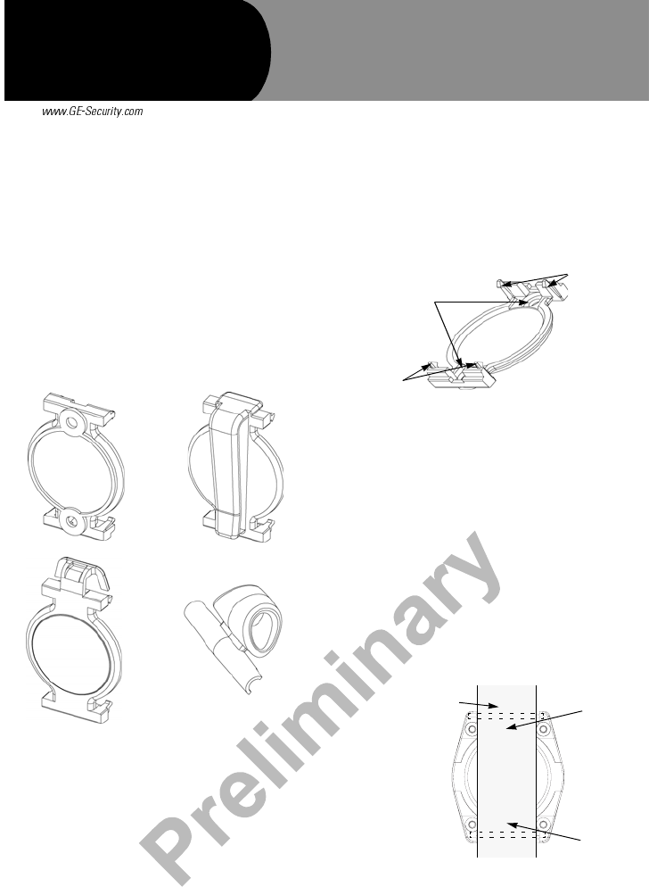
Assembly Options
Wall Mount
1. Place the wall mount adapter on the wall at the desired
location and mark through the mounting holes with a
pencil.
2. Secure the holder to the wall with #4 screws. Use
plasterboard anchors where studs are not present.
3. Snap the help button onto the four snap-on posts on
the wall mount adapter.
Belt Clip
The help button can be worn on the belt using the belt
clip adapter. Snap the help button onto the four snap-on
posts on the belt clip adapter.
Wrist Bands
The help button can be worn on the wrist with a hook and
latch or plastic wrist band.
To use the hook and latch wrist band:
1. Lay the hook and latch wrist band across the back of
the help button.
2. Compress the spring-loaded pins with a small screw-
driver
3. Slip the pins over the wrist band and into the pin slots
located on the back of the help button.
Note
Listen for a clicking sound as the pins slide into the slots.
Wall Mount Adapter Belt Clip Adapter
Pendant Adapter
Pin-Mounted Necklace
Adapter
Snap-On
Posts
Mounting
Holes
Snap-On
Posts
Hook and Latch
Wrist Band Insert Pin
Insert Pin
Document Number: 466-1815 Rev. E
May 2004 PRELIMINARY
:DWHU5HVLVWDQW
3HUVRQDO+HOS%XWWRQ
2
To use the plastic wrist band
1. Insert the spring-loaded pins through the ends of the
plastic wrist band.
2. Compress the spring-loaded pins with a small screw-
driver.
3. Slip into the pin slots located on the back of the help
button.
Note
The plastic wrist band or almost any other 18 mm watch
band can be used.
Pendant
The help button can be worn as a pendant two different
ways:
•With a necklace using the pin-mounted necklace
adapter
•With the included rope necklace using the snap-on
pendant adapter.
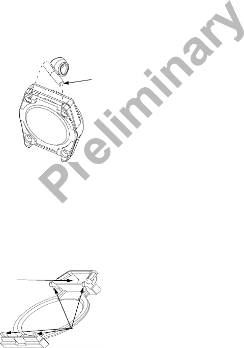
To use the pin-mounted necklace adapter:
1. Make sure the necklace or chain fits through the larger
hole in the pin-mounted necklace adapter.
2. Remove one of the spring-loaded pins from the plastic
wrist band and insert it into the smaller hole on the
necklace adapter.
3. Compress the spring-loaded pins with a small screw-
driver and slip them into the pin slots located on the
back of the help button.
To use the pendant adapter:
1. Slip the rope necklace into the top slot on the pendant
adapter and hook the plastic ends together.
2. Snap the help button onto the four snap-on posts on
the pendant adapter.
Programming
This section describes the basic steps for adding the help
button to panel memory. For complete instructions, refer
to the specific panel Installation Instructions.
1. Set the panel in the program mode.
2. Enter the appropriate group number when prompted
by the panel.
3. Select the desired sensor number when prompted by
the panel.
4. When prompted by the panel to trip the sensor, press
the help button until the light blinks.
5. Exit from program mode.
Testing the Help Button
This section describes the basic steps for testing the help
button. For complete instructions, refer to the specific
panel Installation Instructions.
1. Set the system to the Dealer Sensor Test mode.
2. Activate the help button by grasping the help button in
your hand pressing it with your thumb or finger until
the light blinks.
3. Listen for beeps sounded from system sirens. You
should hear at least 7 beeps.
4. Test the help button from several locations within the
premises to check for consistent response.
5. Instruct the user to test the help button weekly.
Pin-Mount Adapter
Insert
Pin
Slip
Rope Necklace
Through
Snap-On
Posts
3
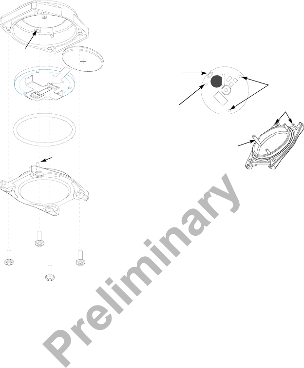
Repair of the Help Button
Use the following diagram and instructions when replac-
ing the battery or cover.
Caution!
To avoid an alarm condition you must place the panel in
sensor test mode before changing the battery.
You must be free of all static electricity before handling the
transmitter circuit board. Touch a grounded, bare metal sur-
face before touching the circuit board, or wear a grounding
strap.
To Replace the Battery:
1. Disassemble the help button by removing the four
screws on the back of the help button and separate the
cover and base.
Note
You may need to “rock” the cover to loosen it due to the
tight seal created by the o-ring.
2. Remove the old battery from its holder and install the
new battery, observing polarity.
Note
Install Duracell (DL2032), Panasonic or Varta (CR2032)
3. Reassemble the help button. Make sure to line up the
LED indicator bump on the cover with the LED on the
PCB.
Caution!
If the board is not correctly lined up with the cover, it can
create stress on the plastic. Be careful not to bend or break
the rectangular snap-on latch supports when reassembling
the help button.
Caution!
Be sure to assemble the help button correctly to ensure
water resistance. Inspect the rubber o-ring before assembly
and be especially careful not to nick or damage it.
4. Test the help button as described in “Testing the Help
Button” section.
To Replace the Cover:
Order the Accessory Kit (Part No. 60-968) to obtain a
new cover.
1. Disassemble the help button by removing the four
screws on the back of the help button and separate the
cover and base.
Note
You may need to “rock” the cover to loosen it due to the
tight seal created by the o-ring.
2. Reassemble the help button using the new cover.
Make sure to line up the LED indicator bump on the
cover with the LED on the PCB.
Lithium Battery Disposal
Expired Lithium batteries are considered hazardous
waste. Be sure to properly dispose of old batteries. Con-
tact your local government for hazardous waste disposal
regulations.
Cover
Battery
Rubber O-Ring
Base
Mounting Posts (4)
PCB
LED Receptacle
LED Mounting
Holes
Align with
Widest Post
Widest Post
Snap-On Latch
Support
4
Specifications
Model No.: 60-609-95, 60-609-95R
RF Frequency: 319.5 MHz
Compatibility: All GE Security 319.5 MHz Control Panels/
Receivers
Battery Type: 3.0 VDC Lithium
Recommended Battery: Duracell (DL2032), Panasonic or Varta
(CR2032)
Typical Standby Current (µA): < 1
Estimated Battery Life (at 20° C): 4 years
Supervisory Interval: 64 minutes
Typical RF Output Power (mW): .25
Operating Temperature Range: 32° to 120° F (0° to 49° C)
Storage Temperature Range: -30° to 140° F (-34° to 60° C)
Relative Humidity: 5 - 90% non-condensing
Dimensions (inches): 1.5 x 1.3 x .5 (L x W x D) w/o adapters or
wrist bands
Weight (lb): .026
Notices
)*(6HFXULW\