UTC Fire and Security Americas 844-PIR 900MHz PIR Motion Detector User Manual
UTC Fire & Security Americas Corporation, Inc. 900MHz PIR Motion Detector
Installation Manual
)
1
,QVWDOODWLRQ,QVWUXFWLRQV
*(6HFXULW\
Product
Summary
A motion sensor (passive-infrared or PIR) detects movement by sensing the infrared energy
emitted from a body as it moves across its field of view. When this motion is detected, the sensor
transmits an alarm signal.
Install motion sensors to protect areas where door/window sensors are impractical or not needed.
For example, use a motion sensor to protect large areas or open floor plans. Motion sensors can
also provide backup protection in areas where door/window sensors exist.
This wireless motion sensor includes the following features:
• Field-selectable coverage area; 33 or 50 feet
• Field-selectable sensitivity modes; 2-pulse or 4-pulse
• 135-second transmitter lockout time after an alarm that helps extend battery life
• Cover-activated tamper
• Supervisory signal transmitted every 64 minutes to the control panel
• Sensor low battery reports (trouble) to the control panel
Included with the sensor is a thin cardboard undercrawl mask and snap-in plastic masks
(installed at the factory). Self-adhesive masking strips are also included.
Installation • If possible, locate sensors within 100 feet of the panel. While a transmitter may have an
open-air range of 500 feet or more, the installation site can have a significant effect on trans-
mitter range. Changing the sensor location may help overcome adverse wireless conditions.
• Mount the sensor permanently on a flat wall or in a corner. Do not set it on a shelf.
• For installations without pets, the required mounting height is 7 1/2 feet.
• Mount the motion sensor on an insulated, outside wall facing in.
• Mount the motion sensor on a rigid surface which is free from vibrations.
• Position the sensor so it faces a solid reference point, like a wall.
• Do not aim the sensor at windows, fireplaces, air conditioners, heaters/heating vents, or place
it in direct sunlight.
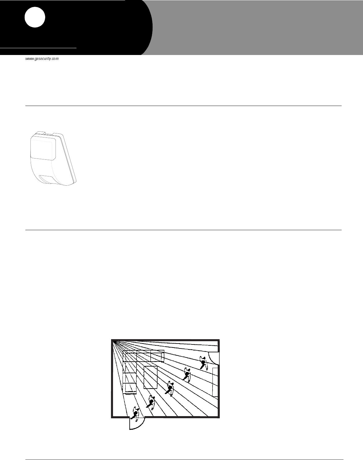
• Position the sensor to protect an area where intruders are most likely to walk across the
detection pattern (see Figure 1).
Figure 1. Overhead (Bird’s Eye View) Detection Path
Person walking across detection path.
'RFXPHQW1XPEHU;;5HY
6HSWHPEHU
35(/,0,1$5<
Preliminary 9/1/04
6HQWURO$3::LUHOHVV3,5
0RWLRQ6HQVRU
Model No.
60-991-900
2Sentrol AP750W Wireless PIR Motion Sensor Installation Instructions
Preliminary 9/1/04
• Do not mount the sensor near duct work or other large metallic surfaces which may affect the
RF signals (see “Final Testing” on page 4). Actual acceptable transmitter range should be ver-
ified for each installation.
• Windows should be closed in any area which has an armed motion sensor.
Note
The cardboard undercrawl
mask should remain
installed when sensor
jumper J1 is set to the BI
position. See the section
“Setting the Sensor Cover-
age Area and Sensitivity” for
complete information on
sensor jumper settings.
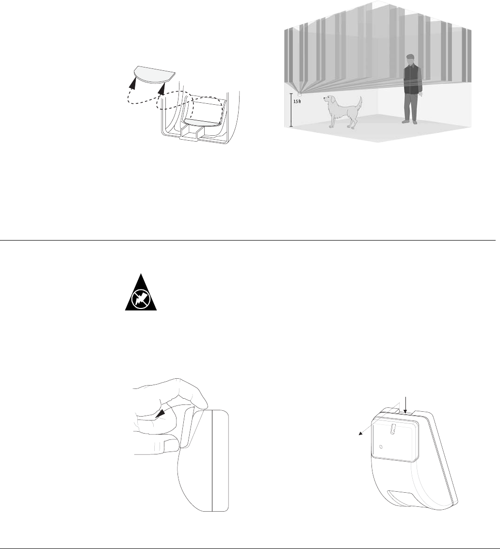
• The cardboard undercrawl mask installed at the factory (see Figure 2) blocks coverage within
5 feet of the sensor.
• For installations where pets are present, mount the sensor upside down about 3.5 feet above
the floor (see Figure 3). Leave the factory-installed undercrawl mask in place to block any
detection pattern directed at the ceiling
Tools and Supplies Needed
• Phillips screwdriver
• Anchors and screws for mounting (included)
• Masks (included)
Mounting the
Motion Sensor
This section describes how to mount the sensor on a flat wall or in a corner.
You must be free of static electricity before handling circuit boards. Wear a
grounding strap or touch a bare metal surface to discharge static electricity.
Static
Note
Remove the factory-installed
plastic masks before mount-
ing. Re-install as desired
after walk testing.
1. Remove the small cover (see Figure 4)
2. Open the sensor housing by pressing down on the top rear and pulling the front cover at the
top (see Figure 5). Set the front cover aside
Figure 2. Cardboard Undercrawl Figure 3. Pet Alley Application
Mask Location
S T E P 1 :
P R E S S D O W N
W I T H I N D E X F I N G E R
S T E P 2 :
P U L L A W A Y
Figure 4. Removing the Small Cover Figure 5. Opening the Sensor Housing
3Sentrol AP750W Wireless PIR Motion Sensor Installation Instructions
Preliminary 9/1/04
Note Avoid touching the
mirror. Fingerprints may
affect detection coverage.
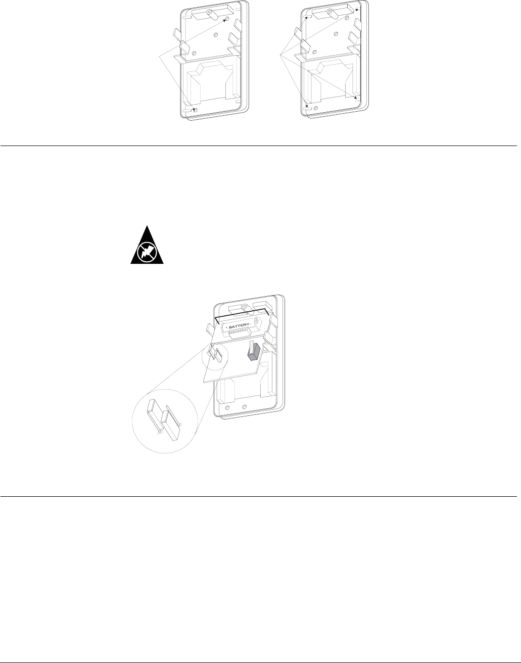
3. Mount the sensor on a flat wall or in a corner, using the appropriate mounting holes (see Fig-
ure 6). Use wall anchors and screws to secure the sensor.
Figure 6. Mounting Hole Locations
Setting the
Sensor
Coverage Area
and Sensitivity
Jumper J1 determines the sensitivity mode of the sensor, either standard or bi-curtain. Jumper J2
determines the coverage area of the sensor, either 33 or 50 feet. See Figure 7 for jumper positions.
Use the standard (STD) setting for wide-angle coverage and single curtain pattern. Use the bi-cur-
tain (BI) setting for added stability to help reduce false alarms. This mode requires intruders to be
detected by two curtains of coverage.
Note
Do not use the bi-curtain
mode for detection in areas
within 5 feet of the sensor.
When selecting bi-curtain
mode, always leave the
cardboard undercrawl mask
installed.
You must be free of static electricity before handling circuit boards. Wear a
grounding strap or touch a bare metal surface to discharge static electricity.
Static
Figure 7. Sensitivity Mode and Coverage Area Jumper Settings
Walk Testing Walk testing should be done to determine the actual coverage area of the sensor. The edge of the
coverage pattern is determined by the first LED flash. This may change slightly depending on the
sensitivity setting. Walk test the unit from both directions to determine the pattern boundaries.
1. Remove the sensor cover to activate the tamper switch, then reattach it to activate the 2-
minute walk test mode.
2. Walk across the coverage pattern to determine the coverage area, indicated by LED activation.
After 2 minutes, the walk test mode and the LED will no longer activate when motion is detected.
Note
Excessive use of the walk test mode may reduce battery life. Use only for initial setup and maintenance
testing. In normal operation mode, the sensor only transmits an alarm signal 135 seconds after the pre-
vious alarm. This reduces unnecessary RF transmissions in high traffic areas, thereby extending battery
life.
C O R N E R
M O U N T I N G
H O L E S
( 4 )
F L A T
M
O U N T I N G
H O L E S
( 2 )
M I R R O R M I R R O R
J 1 J 2
J 1
J 2
J 1 - S E N S I T I V I T Y M O D E
B I = J U M P E R O N T O P T W O P I N S
S T D = J U M P E R O N L O W E R T W O P I N S
J 2 - C O V E R A G E A R E A
5 0 F T = J U M P E R O N T O P T W O P I N S
3 3 F T = J U M P E R O N L O W E R T W O P I N S
4Sentrol AP750W Wireless PIR Motion Sensor Installation Instructions
Preliminary 9/1/04
Environment Testing
Activate the walk test mode, then turn on all heating or air conditioning sources which would nor-
mally be active during the protection period. Stand away from the sensor and outside the cover-
age pattern and watch for alarms.
Installing Masks After determining the full coverage area and performing the environment test, you may need or
want to mask (block) certain parts of the coverage.
Self-Adhesive Masks
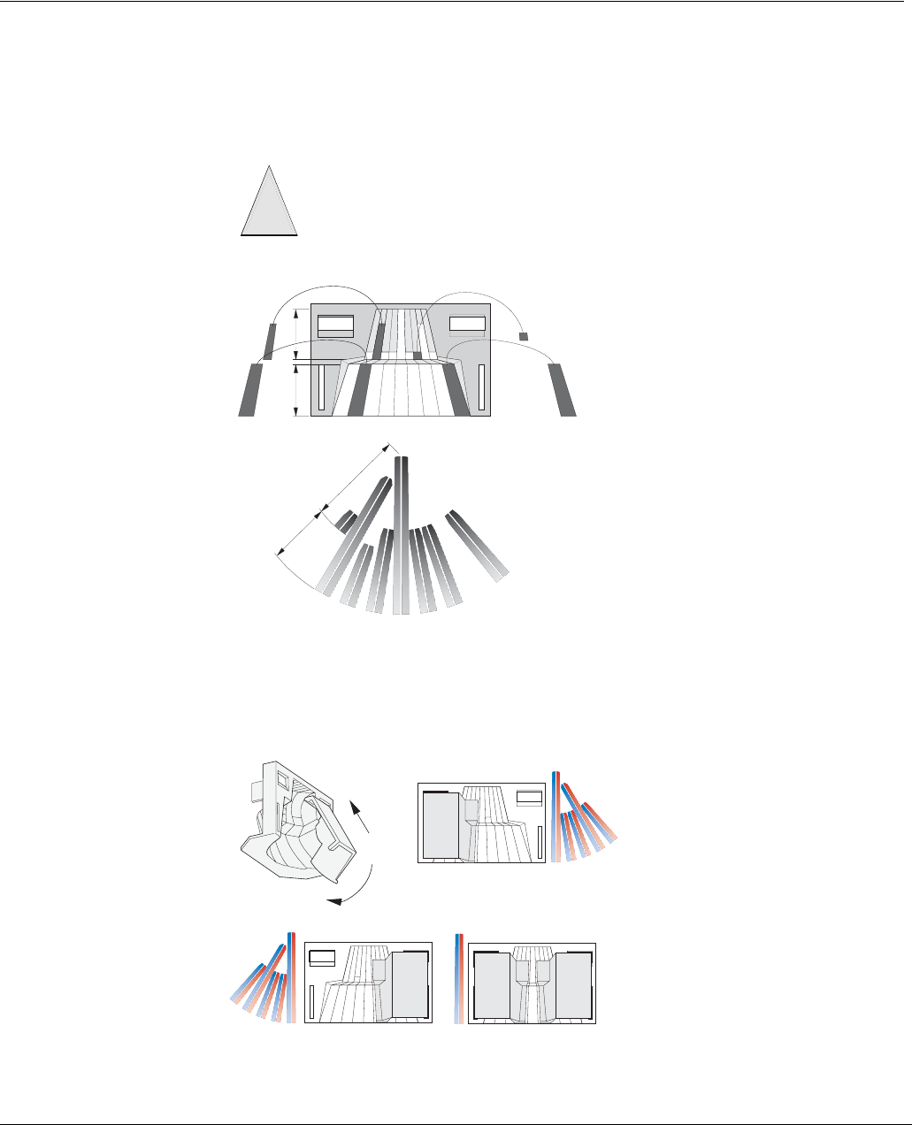
Block the appropriate mirror sections with these masks. Figure 8 shows an example of where to
apply the masks and the resulting coverage area.
Figure 8. Installing Self-Adhesive Masks
Plastic Masks
Install these masks for half coverage or narrow coverage applications (see Figure 9)
Note
After installing masks,
always conduct a walk test
and environment test to ver-
ify the coverage area is cor-
rect for the application.
Figure 9. Installing Plastic Masks
To avoid damaging the mirror do not remove the masks using a sharp tool. If
necessary, remove masks by carefully peeling them off with your fingers.
Caution
!
A
B
1 9
A
B
1
2345678
23456789
9
8
7
6
5
4
3
2
1
2
1
21
a
b
INSTALLING
PLASTIC
HALF COVERAGE-ONE
HALF COVERAGE-ONE NARROW COVERAGE-BOTH
5Sentrol AP750W Wireless PIR Motion Sensor Installation Instructions
Preliminary 9/1/04
Programming The following describes the basic steps for adding (learning) the sensor into panel memory. Refer
to the specific panel installation instructions for complete programming information.
1. Put the panel into program mode.
2. Advance to the learn sensors menu.
3. Enter the appropriate sensor group and desired sensor number.
4. When the panel prompts you to trip the sensor, activate the sensor tamper switch by removing
the sensor cover.
5. Reattach the sensor cover.
6. Exit from program mode.
Final Testing Final testing should be done to verify radio signal integrity and confirm control panel program-
ming and response. The actual transmitter range can be determined by performing a sensor test as
described below. Refer to the specific panel installation instructions for complete sensor testing
information.
1. After the sensor has been mounted, remove the sensor cover to trip the tamper switch and acti-
vate the walk test mode.
2. Replace the sensor cover.
3. Place the control panel in test mode.
4. Move across the detection pattern until the sensor LED turns on, then STOP your motion.
5. Listen for the appropriate system response. If the system does not respond, proceed to the
“Troubleshooting” section.
Maintenance At least once a year, the sensor should be tested to verify correct operation. The end user should
be instructed to put the sensor in walk test mode and walk through the far end of the coverage pat-
tern to verify proper detection.
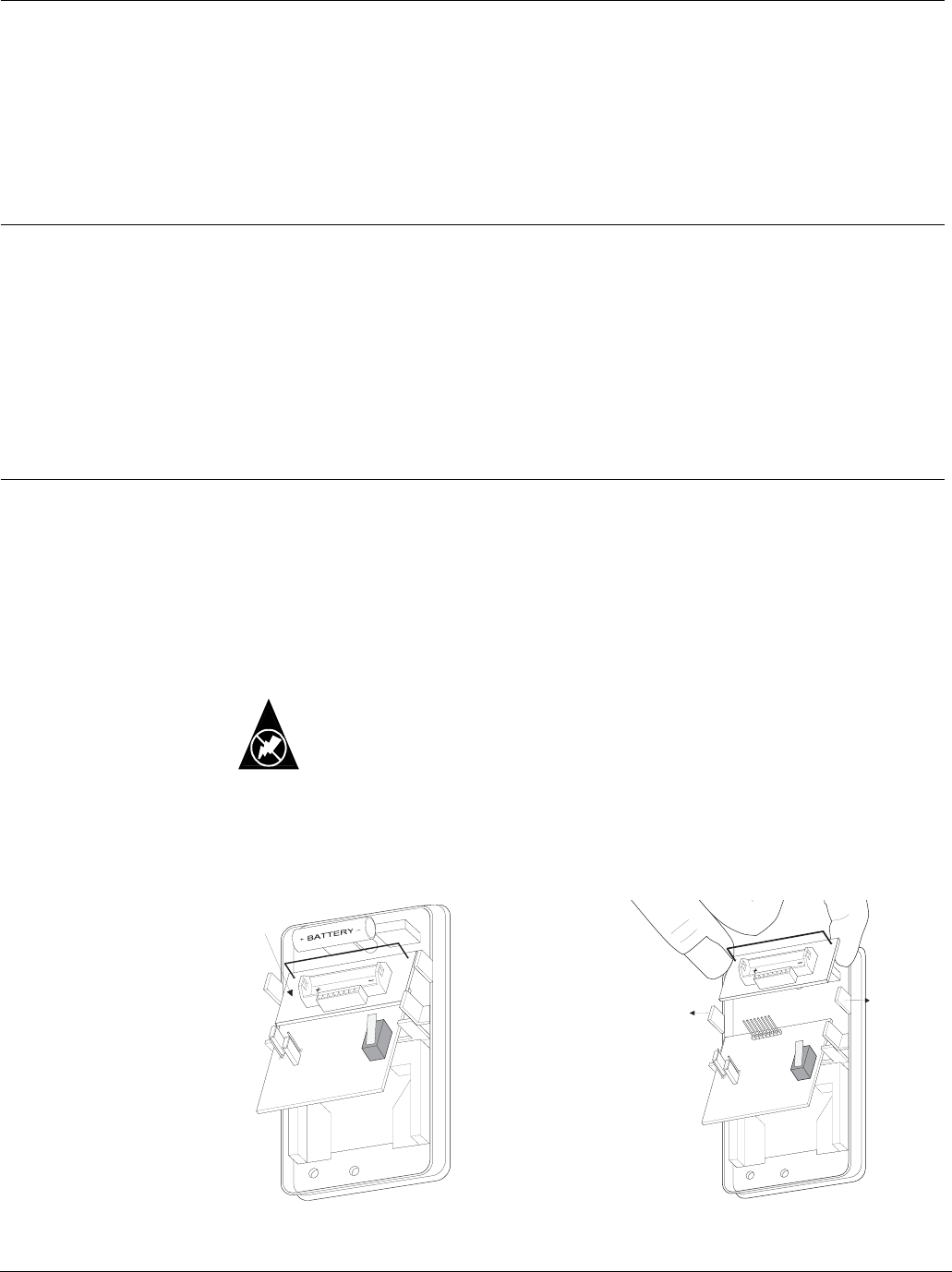
Replacing Batteries
When battery replacement is necessary, observe proper polarity (positive +, negative -) when
installing the new batteries, or the sensor may be damaged.
Use only exact replacement 3-volt lithium batteries (CR123A).
You must be free of static electricity before handling circuit boards. Wear a
grounding strap or touch a bare metal surface to discharge static electricity.
Static
1. Remove the sensor cover (see Figures 4 and 5) and set it aside.
2. Remove the transmitter (upper) circuit board battery (see Figure 10)
3. Remove the transmitter circuit board and place it inside the cover (see Figure 11)
T R A N S M I T T E R
BOARD
P U L L O U T O N
E I T H E R T A B
W H I L E P U L L I N G
T R A N S M I T T E R
BOARD UP.
Figure 10. Removing the Transmitter Battery Figure 11. Removing the Transmitter Circuit Boar
d
6Sentrol AP750W Wireless PIR Motion Sensor Installation Instructions
Preliminary 9/1/04
Note
Avoid touching the mirror.
Fingerprints may affect
detection coverage
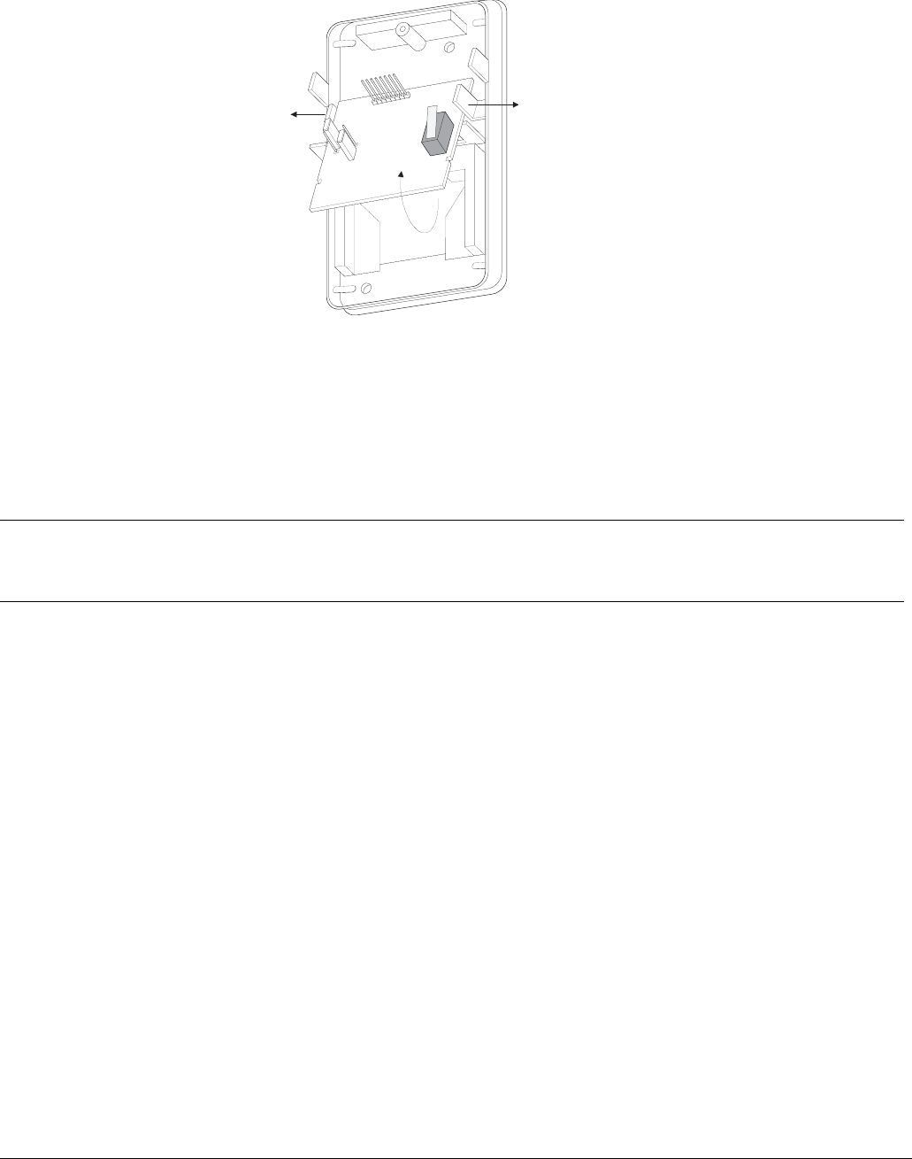
4. Carefully remove the PIR (lower) circuit board by pressing outward on either side tab, then
pull up on the circuit board (see Figure 12).
Figure 12.Removing the PIR Circuit Board
5. Remove the PIR circuit board battery (located on opposite side of components) and install a
new one, observing polarity (marked on the circuit board).
6. Re-install the PIR circuit board into the sensor plastic.
7. Re-install the transmitter circuit board onto the PIR circuit board.
8. Install a new battery in the transmitter circuit board, observing polarity (marked in battery
bucket).
After replacing batteries, wait at least 3 minutes before activating the walk test mode.
Lithium Battery
Disposal
Lithium batteries that are no longer usable are considered hazardous waste. Be sure to properly
dispose of the old batteries. Contact your local city government for hazardous waste disposal
laws.
Troubleshooting Use the following guidelines if the system does not respond correctly when the sensor is acti-
vated.
• Check programming and re-program sensor into panel if necessary.
• Move the sensor to another location and test for correct response.
• Test a known good sensor at the same location.
• If the system does not respond, avoid mounting a sensor at that location.
• If the replacement sensor functions, return the problem sensor for repair or replacement.
P U L L O U T O N
E I T H E R T A B . . .
. . . W H I L E P U L L I N G
T R A N S M I T T E R
B O A R D U P .
M I R R O R

7Sentrol AP750W Wireless PIR Motion Sensor Installation Instructions
Preliminary 9/1/04
Specifications Compatibility: .......................... All GE Security 900 MHz. Panels/Receivers
Power source:........................... Two 3-volt lithium (CR123A) batteries
Typical battery life: ................. 2-4 years at 68° F (not verified by U.L.)
Operating temperature range: 10° to 110° F (-12° to 43° C)
Storage temperature:............... -40° to 140° F (-40° to 60° C)
Operating relative humidity:.. 5% to 95% non-condensing
Storage relative humidity:....... 95% maximum non-condensing (up to 6 months)
Dimensions: .............................. 4.75 in. (12.7 cm) x 2.60 in. (6.6 cm) x 2.0 in. (5.1 cm) (L x W x D)
Notices These devices comply with part 15 of the FCC rules. Operation is subject to the following two conditions:
1. These devices may not cause harmful interference.
2. These devices must accept any interference received, including interference that may cause undesired
operation.
Changes or modifications not expressly approved by Interactive Technologies, Inc. can void the users’
authority to operate the equipment.
FCC ID: B4Z-844-PIR
U.S. Patent Nos: 4,855,713, 4,864,636, 5,761,206, 5,805,063, 5,872,512, and 5,942,981

8Sentrol AP750W Wireless PIR Motion Sensor Installation Instructions
Preliminary 9/1/04
)
*(6HFXULW\