UTC Fire and Security Americas 846-TCVR 900MHz Bus Transceiver User Manual
UTC Fire & Security Americas Corporation, Inc. 900MHz Bus Transceiver
Install Manual
1
,QVWDOODWLRQ,QVWUXFWLRQV
*(6HFXULW\
'
Preliminary 3/1/04
Product
Summary
The SuperBus 2000 900 MHz RF Transceiver Module is a UL listed device that adds or expands
panel wireless zone capacity. See the specific panel Installation Instructions for complete UL
requirements for the system you are installing.
The transceiver is compatible with all GE Security 900 MHz wireless sensors and touchpads,
and can be located up to 2,800 feet away from the panel (see Table 2). It receives information
from wireless sensors and touchpads then sends the data to the panel via the SuperBus 2000 dig-
ital data bus. It also transmits information to other transceivers. Power for the module is pro-
vided by the panel.
Transceivers are available in 16-zone (-16Z), 32-zone (-32Z), or panel maximum (-MAX) capac-
ities.
The SuperBus 2000 RF Transceiver Module features:
• Compatibility with all GE Security 900 MHz wireless sensors, touchpads, and sirens.
• Backward compatibility with SuperBus panels.
• 1,500 feet nominal, open air receiving range.
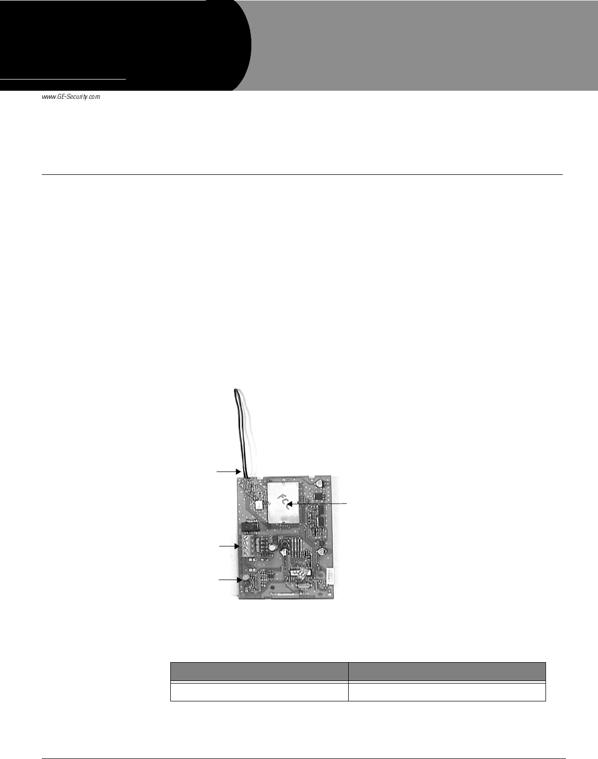
Figure 1 shows the transceiver module components and Table 1 describes those components.
Figure 1. Transceiver Board
Table 1: Component Descriptions
Component Function
Antenna Provide communication with wireless devices.
Antenna
LEDs
Terminal
Strip
Device ID
Label
'RFXPHQW1XPEHU5HY$
)HEUXDU\
35(/,0,1$5<
6XSHU%XV0+=5)
7UDQVFHLYHU0RGXOH
3DUW1R
2SuperBus 2000 900MHZ RF Transceiver Module Installation Instructions
Preliminary 3/1/04
Installation Installation Guidelines
Observe the following guidelines when installing the transceiver module:
• Concord™ systems can accommodate a maximum of 96 wireless sensors/zones.
• In Concord systems, up to 16 SuperBus 2000 devices can be connected to the panel
(SuperBus 2000 Touchpads, Receivers, Transceivers, HIMs, HOMs, ESMs, etc.).
• Each bus device must have a different unit number.
• Leave 4 inches above the module for the antenna.
• When mounting the module away from the panel, use the wire length guidelines in
Table 2.
• Avoid areas that are likely to expose the module to moisture.
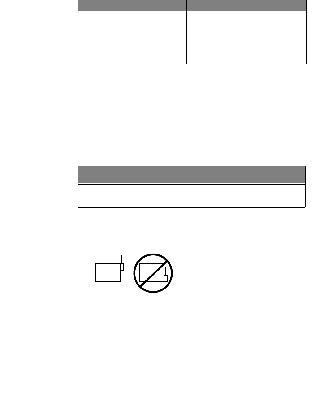
• Avoid areas with excessive metal or electrical wiring, including furnace and utility
rooms. If unavoidable, mount on or near metal with the antenna extending above the
metallic surfaces, as shown in Figure 2.
Figure 2. Mounting on or Near Metal
Tools and Supplies
• Screwdrivers
• Drill with bits
• Mounting screws and anchors (included)
• 4-conductor, 22-gauge or larger, stranded wire
• Support standoff (included with Concord cabinet)
• ¼-inch press-fit reed switch and magnet (not included)
• Small hammer
Mounting the Transceiver
The module can be mounted on any interior wall (protected from the elements).
SuperBus 2000 Device ID Number Label Identifies unique module SuperBus 2000
device ID number (SuperBus 2000 panels).
Transceiver Status LED On continuously when the transceiver is
powered. Flashes when an RF signal is
received.
Terminal Strip Used for power and bus connections to panel.
Table 1: Component Descriptions
Component Function
Table 2: Maximum Module Wire Lengths
Wire Gauge (Unshielded or
Shielded)
Max. Wire Length Between Module and Concord
Panel
18 2,800 feet
22 1,100 feet
METAL METAL
3SuperBus 2000 900MHZ RF Transceiver Module Installation Instructions
Preliminary 3/1/04
¾To mount the module on a wall:
1. Remove the panel AC power transformer and disconnect the backup battery.
2. Remove the module cover and set it aside.
3. Hold the base against the mounting surface and mark the three mounting holes. Remember to
leave at least 10 inches above the base for the antenna.
4. Drill holes and insert the appropriate anchors.
5. Secure the back-plate to the wall with included panhead screws.
Concord Panel Wiring
This section describes how to wire the transceiver module to Concord panels.
¾To wire the transceiver module to Concord panels:
1. Disconnect the panel power transformer and backup battery.
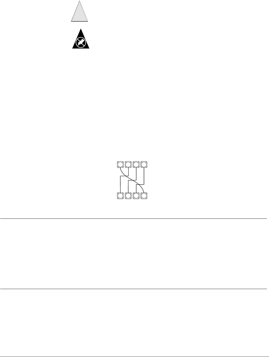
2. Wire the module to the panel power and bus terminals as shown in Figure 3.
Figure 3. Wiring Module to Concord Panel
Power Up Use the following procedures for powering up the system and verifying bus communication.
Note
In order to enter panel pro-
gram mode to verify unit
numbers, an alphanumeric
touchpad must be con-
nected to all Concord pan-
els.
¾To power up the panel and transceiver module:
1. Verify that all wiring at the panel, touchpad, and transceiver is correct.
2. Connect the panel backup battery and plug in the panel AC power transformer.
3. Verify that the transceiver module status LED is on.
4. If desired, enter panel program mode to verify unit number exists (see panel Installation
Instructions for more information).
Note
If the transceiver module LED is not on, unplug the panel AC power transformer, disconnect the backup
battery, and see Table 3 “Troubleshooting”.
Specifications Compatibility:............................GE Security Concord panels. GE Security 900 MHz wireless sensors and
touchpads
Power Required: ........................12 VDC nominal 500 mA maximum draw (from panel)
Storage Temperature:.................-30° to 140°F (-34° to 60°C)
Operating Temperature:.............32° to 140°F (0° to 60°C)
Maximum Humidity: .................90% relative humidity, noncondensing
Wireless Signal Range:..............1,500 feet nominal, 2,000 feet typical open air (may vary with application)
Dimensions: ..............................4.125” x 5.25” x 1.0” (L x W x H), excluding antenna
To prevent damaging the panel or module, remove the panel AC power transformer
and disconnect the backup battery before installation.
Caution
!
You must be free of static electricity before handling circuit boards. Wear a ground-
ing strap or touch a bare metal surface to discharge static electricity.
Static
63 4 5
PANEL
TERMINAL STRIP
+12
VDC BUS
ABUS
B
GND
SUPERBUS 2000
RF TRANSCEIVER MODULE
TERMINAL STRIP
41 2 3
+12
VDC BUS
A
BUS
BGND
4SuperBus 2000 900MHZ RF Transceiver Module Installation Instructions
Preliminary 3/1/04
)
*(6HFXULW\