UTC Fire and Security Americas 914E-DWS Wireless Door-Window Sensor User Manual 466 2298C 319 5 dw inin
UTC Fire & Security Americas Corporation, Inc. Wireless Door-Window Sensor 466 2298C 319 5 dw inin
user manual
466-2298C • June 2009
Copyright © 2009 GE Security
g319.5 Crystal Maxlife Door/Window Sensor
Installation Instructions
Introduction
These are the GE
319.5 Crystal Maxlife Door/Window Sensor
Installation Instructions
for models 60-362N-10-319.5 and 60-
362N-11-319.5. Install the sensor (
Figure 1
) on doors, windows,
and other objects that open and close. The sensor transmits signals
to the control panel when a magnet mounted near the sensor is
moved away from or closer to the sensor. The sensor is equipped
with a cover tamper microswitch for additional security.
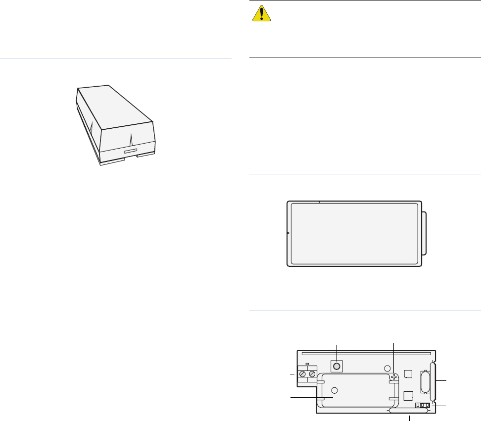
Figure 1. Sensor
Use the following installation guidelines:
• Mount the sensor on the door frame and the magnet on the
door. For double doors, mount the sensor on the least-used
door and the magnet on the most-used door.
• Where possible, install sensors within 100 ft. (30 m) of the
panel. While a transmitter may have an open-air range of
500 ft. (150 m) or more, the environment at the installation
site may have a significant affect on operational range.
Changing a sensor location may improve wireless commu-
nication.
• Line up the alignment mark on the magnet to one of the
alignment marks on the sensor.
• Mount sensors at least 4.7 in. (12 cm) above the floor to
avoid potential damage.
• Avoid mounting sensors in areas where they will be exposed
to moisture or where the operating temperature range will
exceed the specified range.
• If possible, mount directly to a stud. If a stud is not avail-
able, use plastic anchors.
• Avoid mounting the sensor in areas with a large quantity of
metal or electrical wiring.
• Only one input can be used at any given time.
• You must mount the magnet within 3/8 in. (0.95 cm) of the
sensor.
• Mount sensors with screws, not double-sided tape.
• Only install the EOL resistor when an external contact is
used.
You will need the following tools and materials:
• Two #6 x 1.00 in. PPH (Phillips panhead) screws and two
plastic anchors for mounting the sensor (included).
• Two #6 x 0.625 in. PPH screws for mounting the magnet
(included).
• External contact 4.7 Kohm end-of-line (EOL) resistor
(included).
• Phillips screwdriver
Programming
This section describes general guidelines for programming
(learning) the sensor into panel memory. Refer to the specific
panel or receiver documentation for complete programming
details.
To program the sensor:
1. Remove the sensor cover by squeezing the cover ends
firmly releasing the tab (Figure 2) from sensor base slot.
Figure 2. Sensor tab
2. If required, insert the battery into the battery holder,
observing correct polarity (Figure 3).
Figure 3. Board components
3. Set the panel to program mode.
4. Proceed to the Learn sensors menu.
5. Set the external contact in the alarm condition (see External
contact wiring on page 3).
6. Press and release the tamper switch (Figure 3) on the sensor
until the panel responds.
7. Select the appropriate sensor group and number.
8. Exit program mode.
CAUTION: You must be free of all static electricity
when handling electronic components. Touch a
grounded, bare metal surface before touching a
circuit board or wear a grounded wrist strap.
Tab
Tamper switch
Battery
holder
Reed A
Input
jumper
Reed B
Positive
External
Contact
Terminals
319.5 Crystal Maxlife Door/Window Sensor
Installation Instructions
2
Input selection
Only one door/window input can be used at any given time. For
example, if the external contact is used, internal reed switches
(Reed A and Reed B in Figure 3 on page 1) cannot be used.
Note: Power down the device before positioning the input selection.
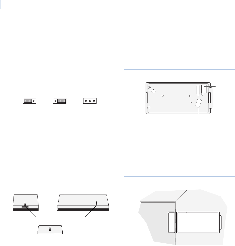
See Figure 4 and position the input selection jumper to select:
Reed B. Left two pins covered (default).
Reed A. Right two pins covered.
External contact. Jumper removed.
Figure 4. Input selection jumper
Verify RF communication
Before mounting the sensor, verify the sensor mounting location
provides good RF panel communication.
To verify:
1. Put the panel/receiver into sensor test mode.
2. Take the sensor to the mounting location.
3. Hold the magnet next to the alignment mark on the the
sensor (Figure 5) and then pull the magnet away from the
sensor.
Figure 5. Alignment marks
4. Listen for siren beeps to determine appropriate response
(refer to the specific panel/receiver documentation).
5. Exit sensor test mode.
Mounting
To mount the sensor:
1. Remove the sensor battery.
2. Remove the circuit board from the sensor base by pulling
back on the plastic tab.
3. Mount the sensor base using the screws provided
(Figure 6).
Figure 6. Mounting holes
4. Replace the circuit board.
5. Remove the magnet from its base.
6. Line up the magnet alignment mark with the sensor align-
ment mark, depending on the internal reed switch being
used (Figure 5).
7. Mount the magnet base with the #6 x 0.625 in. PPH screws
no more than 3/8 in. (0.95 cm) away from the sensor base
(Figure 7). Replace the magnet cover.
Figure 7. Mounted sensor
8. Insert the sensor battery observing correct polarity (Figure 3
on page 1).
9. Attach the sensor cover to the base.
Reed B Reed A External contact
(default)
Sensor end view Sensor side view
Magnet
Alignment marks
Mounting
hole
Mounting
hole
Wire
entry
Door Door frame
Magnet Sensor
3
External contact wiring
Use the following specifications for the external contact:
• Maximum wire length: 26 ft. (8 m).
• Wire: Stranded, 22-gauge (0.7112 mm).
• Switches: Hermetically sealed external switches (sealed
reed switches) that supply a minimum 250 ms open or close
on alarm.
Note: Do not connect more than five external contacts to a door/
window sensor.
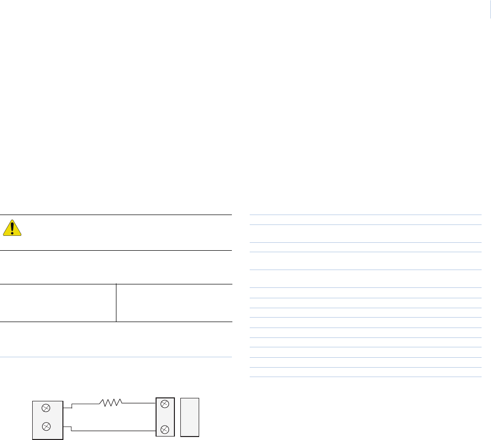
You can wire the sensor terminal blocks with leads from an
external contact (Figure 8). The door/window sensor provides
alarm and tamper indication. Wire the external contact with one
end-of-line (EOL) resistor in series with the external contact.
This gives the following readings for each configuration:
Figure 8 shows external contact wiring (normally closed and
normally open).
Figure 8. External contact wiring
Sensor test
The sensor test verifies proper communication between the
sensor and the panel/receiver. To test the sensor, refer to the
specific panel/receiver documentation and do the following:
1. Put the panel/receiver into sensor test mode.
2. Open the door/window the sensor is protecting. The sensor
transmits a signal.
3. Listen for siren beeps to determine the appropriate response.
4. Exit sensor test mode.
Battery replacement
When the system indicates low sensor battery, replace it immedi-
ately. Use the recommended replacement batteries (see
Specifica-
tions
).
To replace the batteries:
1. Remove the sensor cover.
2. Remove the battery. Follow local laws for battery disposal.
3. Insert the replacement battery, observing correct polarity
(Figure 3 on page 1).
4. Perform a sensor test with the panel. See Sensor test.
Specifications
CAUTION: You must install the EOL resistor at the
external detection device for proper supervision.
Normally closed
Zero ohm/short = Tamper
4.7 Kohm = Normal
Open = Alarm
Normally open
Zero ohm/short = Tamper
4.7 Kohm = Alarm
Open = Normal
Door/Window Contacts
EOL resistor
Sensor
4.7 Kohm
Model number Brown: 60-362N-11-319.5
White: 60-362N-10-319.5
Frequency 319.5 MHz
Compatibility GE Security 319.5 MHz control panels/
receivers
Battery type 3.0 V, 1300 mAh lithium
Required batteries Duracell DL 123A, Panasonic CR123A, Sanyo
CR123A, Varta CR123A
Estimated battery life 5 to 10 years at 20°C (68°F) depending on the
number of activations per day
Magnet gap 3/8 in. (max.)
Supervisory interval 64 minutes
End-of-line resistor 4.7 Kohm
Typical RF output power 0.25mW EIRP
Operating temperature 10 to 120°F (-12 to 49°C)
Storage temperature -30 to 140°F (-34 to 60°C)
Relative humidity 0 to 90% noncondensing
Dimensions (L x W x D) 3.02 x 1.5 x 1.02in. (81 x 38 x 26 mm)
Weight 44 g
Listings UL 1023, UL 1610
FCC This device complies with part 15 of the FCC rules. Operation is
subject to the following conditions:
This device may not cause harmful interference.
This device must accept any interference received, including inter-
ference that may cause undesired operation.
Changes or modifications not expressly approved by the party
responsible for compliance could void the user’s authority to
operate the equipment.
FCC ID: B4Z-914E-DWS
IC: 1175C-914EDWS
Technical support
Toll-free: 888.GESECURity (888.437.3287 in the US, including Alaska and Hawaii; Puerto Rico; Canada).
Outside the toll-free area: Contact your local dealer.
www.gesecurity.com