UTC Fire and Security Americas RS325X Camera User Manual
UTC FIRE & SECURITY AMERICAS CORPORATION, INC Camera Users Manual
Users Manual

UltraSync Wi-Fi IP Camera
Installation Guide
TM
P/N 466-5303 • REV 07 • ISS 05JAN17 © 2017 United Technologies Corporation. All rights reserved 1
Contents
Product overview ..................................................................................... 3
Installation environment ........................................................................... 3
Cable requirements .......................................................................... 4
Package contents .................................................................................... 4
UltraSync Wi-Fi IP Bullet Camera .................................................... 4
UltraSync Wi-Fi IP Desktop Camera ................................................ 5
Camera description – Bullet Camera ....................................................... 6
Camera description – Desktop Camera ................................................... 7
Desktop camera LED indicators ....................................................... 8
Accessing the Micro SD card .................................................................. 9
Bullet Camera .................................................................................. 9
Desktop Camera .............................................................................. 9
Mounting ................................................................................................ 10
Bullet Camera ................................................................................ 10
Waterproof jacket assembly .......................................................... 11
Desktop Camera ............................................................................ 12
Browser requirements ........................................................................... 13
Quick setup ........................................................................................... 14
1. Setting up Ethernet/Wi-Fi transmission ...................................... 14
2. Add cameras to a Wi-Fi network ................................................ 15
3. Add cameras to UltraSync .......................................................... 17
4. Reboot cameras ......................................................................... 18
Alternative methods of adding cameras ................................................ 18
Add cameras via Ethernet with a Windows PC .............................. 18
Add cameras via WPS ................................................................... 19
UltraSync app basic functions ............................................................... 20
View Live Stream and Latest Clip .................................................. 20
Program event triggered camera clips ........................................... 20
View event triggered clips in History .............................................. 22
Removing cameras from UltraSync ................................................ 22
Change default camera settings ............................................................ 23
TruVision Device Manager ............................................................. 23
TruVision Navigator ........................................................................ 23
Reset cameras to factory default ........................................................... 24
Reset button ................................................................................... 24
Camera configurator ...................................................................... 24
Troubleshooting ..................................................................................... 25
Specifications ........................................................................................ 27
2 P/N 466-5303 • REV 07 • ISS 05JAN17 © 2017 United Technologies Corporation. All rights reserved
Product overview
This is the installation guide for the following UltraSync IP camera
models:
RS-3230/3231 (1080p IP Wi-Fi Desktop IR camera)
RS-3250/3251 (1080p IP Wi-Fi Bullet IR camera)
Installation environment
When installing your product, consider these factors:
Electrical: Electrical wiring should be installed carefully by
qualified service personnel. Always use a proper Power over
Ethernet (PoE) switch or a 12 VDC UL listed Class 2 or CE
certified power supply to power the camera. Do not overload
the power cord or adapter.
Ventilation: Ensure that the location planned for the
installation of the camera is well ventilated.
Temperature: Do not operate the camera beyond the
specified temperature, humidity or power source ratings. The
operating temperature of the camera is between -30 to +60°C
(-22 to 140°F). Humidity is below 90%.
Moisture: Do not expose the camera to rain or moisture, or try
to operate it in wet areas. Turn the power off immediately if the
camera is wet and ask a qualified service person for servicing.
Moisture can damage the camera and also create the danger
of electric shock.
Servicing: Do not attempt to service this camera yourself. Any
attempt to dismantle or remove the covers from this product
invalidates the warranty and may also result in serious injury.
Refer all servicing to qualified service personnel.
Cleaning: Do not touch the sensor modules with fingers. If
cleaning is necessary, use a clean cloth with some ethanol
and wipe the camera gently. If the camera will not be used for
an extended period of time, put on the lens cap to protect the
sensors from dirt.
Reflectivity: Ensure that there is no reflective surface too
close to the camera lens. The IR light from the camera may
reflect back into the lens causing reflection.
P/N 466-5303 • REV 07 • ISS 05JAN17 © 2017 United Technologies Corporation. All rights reserved 3
Cable requirements
For proper operation, adhere to the following cable and power
requirements for the cameras. Category 5 cabling or better is
recommended. All network cabling must be installed according to
applicable codes and regulations.
Package contents
Check the package and contents for visible damage. If any
components are damaged or missing, do not attempt to use the
unit; contact the supplier immediately. If the unit is returned, it
must be shipped back in its original packaging.
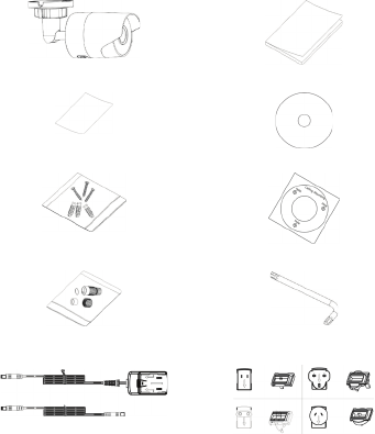
UltraSync Wi-Fi IP Bullet Camera
IP Bullet Camera
Installation Guide
WEEE and Battery Installation
Configuration CD
Anchors and Screws
Mounting Template
Waterproof Jacket (Ethernet)
Hex Wrench
Power Supply and Extension
Power Supply Adapters (US,
EU, UK, and AUS)
4 P/N 466-5303 • REV 07 • ISS 05JAN17 © 2017 United Technologies Corporation. All rights reserved
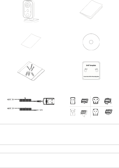
UltraSync Wi-Fi IP Desktop Camera
IP Desktop Camera
Installation Guide
WEEE and Battery Installation
Configuration CD
Anchors and Screws
Mounting Template
Power Supply and Extension
Power Supply Adapters (US,
EU, UK, and AUS)
CAUTION: Use direct plug-in UL listed power supplies marked
Class 2/CE certified or LPS (limited power source) of the required
output rating as listed on the unit.
CAUTION: Risk of explosion if battery is replaced by an incorrect
type. Dispose of used batteries according to the instructions.
P/N 466-5303 • REV 07 • ISS 05JAN17 © 2017 United Technologies Corporation. All rights reserved 5
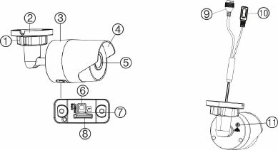
Camera description – Bullet Camera
1
. Adjustment nut
2
. Mounting base
3
. Main body
4
. Sun shield
5
. Lens
6. WPS/RESET button
7. LED indicator
8. Micro SD card slot
9. Ethernet interface
10. Power cable (12 VDC)
11. GND screw
6 P/N 466-5303 • REV 07 • ISS 05JAN17 © 2017 United Technologies Corporation. All rights reserved
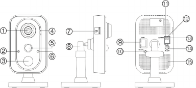
Camera description – Desktop Camera
1
. Lens
2
. Microphone
3
. IR (infrared) LED
4
. LED indicators (see next
page)
5
. PIR (passive infrared) sensor
6
. Light sensor
7
. Micro SD card slot
8. Three-axis bracket
9. Ethernet interface
10. WPS/RESET button
11. I: Alarm input interface
12. G: Grounding
13. O: Alarm output
interface
14. Power supply port (12
VDC)
15. Speaker
P/N 466-5303 • REV 07 • ISS 05JAN17 © 2017 United Technologies Corporation. All rights reserved 7

Desktop camera LED indicators
The following table describes the desktop camera LED behavior
(see item 4 in “Camera description – Desktop Camera” on page
7).
LED State Color Appearance
Alarm Camera alarm triggered Red Solid
Camera alarm not triggered
Blue Solid
Status UltraSync Service
connected
Blue Solid
UltraSync Service
disconnected
None None
Link WPS in process Blue Fast blinking
WPS connection failed Blue Slow blinking
Network communication Amber Blinking
Network disconnected None None
8 P/N 466-5303 • REV 07 • ISS 05JAN17 © 2017 United Technologies Corporation. All rights reserved
Accessing the Micro SD card
An 8 GB Micro SD card is pre-installed in the cameras. Micro SD
cards with up to 128 GB of storage capacity can also be used.
Note: Video and log files stored on the Micro SD card can only be
accessed using the UltraSync App when validated with the
UltraSync Panel.
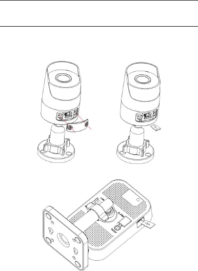
Bullet Camera
To access the Micro SD card slot, remove the cover on the
bottom of the camera.
Desktop Camera
P/N 466-5303 • REV 07 • ISS 05JAN17 © 2017 United Technologies Corporation. All rights reserved 9
Mounting
Before mounting a camera:
Ensure that all the related equipment is powered off during the
physical installation/camera mounting.
Ensure that the wall or ceiling is strong enough to withstand
four times the weight of the camera assembly.
Bullet Camera
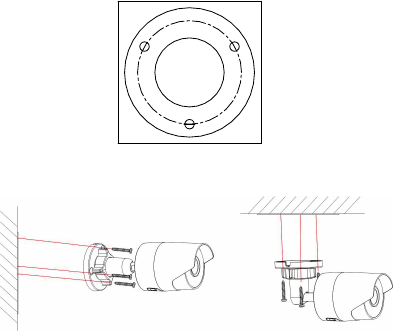
To mount the bullet camera on a wall or ceiling:
1. Drill the holes for the mounting hardware in the mounting
surface using the supplied drill template. To route the cables
from the base of the camera, drill a cable access hole in the
mounting surface.
Ceiling Mounting
Hole
Hole
Hole
2. Route network cables to the mountung location as needed.
3. Secure the camera to the wall or ceiling with the supplied
screws.
4. Connect the power cable and video output cable as needed.
5. Adjust the lens by doing the following:
a. Loosen the adjustable nut.
10 P/N 466-5303 • REV 07 • ISS 05JAN17 © 2017 United Technologies Corporation. All rights reserved
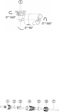
b. Adjust the pan direction [0°~360°].
c. Adjust the tilt direction [0°~90°].
d. Rotate the camera [0~360°] to adjust the lens to the
surveillance angle.
e. Tighten the adjustable nut (1) to complete the installation.
Waterproof jacket assembly
We recommended using the waterproof jacket to protect network
cabling when the camera is installed outdoors.
To assemble the waterproof jacket:
1. Remove the connector (3) from the end of the network cable
(7).
2. Route the network cable through the waterproof jacket
components in the following sequence: fixed nut (6),
waterproof ring (5), and the main body of the waterproof jacket
(4).
3. Insert the waterproof ring into the main body of the waterproof
jacket.
4. Reattach the plug to the end of the network cable.
5. Place the O-ring (2) in the network interface (1) of the camera,
and then connect the network cable.
6. Connect the network interface to the waterproof jacket, and
then rotate the fixed nut clockwise to connect it to the main
body of the waterproof jacket.
1
. Network interface
2
. O-ring
3
. Connector
4. Waterproof jacket
5. Waterproof ring
6. Fixed nut
7. Network cable
P/N 466-5303 • REV 07 • ISS 05JAN17 © 2017 United Technologies Corporation. All rights reserved 11
Desktop Camera
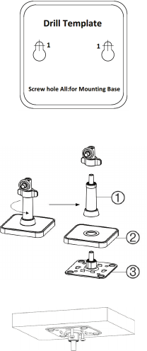
To mount the desktop camera on a wall or ceiling:
1. Drill the screw holes according to the drill template.
2. Disassemble the three-axis bracket. Hold the base (2) with
one hand, and rotate the pole (1) counter-clockwise to
disassemble the pole from the base.
3. Install the fixed tray (item 3 in step 2) to the ceiling or wall with
the supplied screws.
4. Install the base on the fixed tray.
12 P/N 466-5303 • REV 07 • ISS 05JAN17 © 2017 United Technologies Corporation. All rights reserved
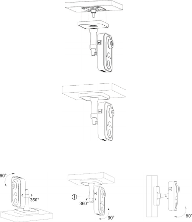
5. Install the camera on the bracket.
6. Adjust the camera angle by doing the following:
a. Loosen the knob (1) to adjust the panning position and
tilting position.
b. When finished adjusting the camera angle, fasten the knob.
Browser requirements
The following browsers are supported for camera setup:
Internet Explorer 8 or later
Safari 5 or later
P/N 466-5303 • REV 07 • ISS 05JAN17 © 2017 United Technologies Corporation. All rights reserved 13

Quick setup
Note: If the light source where the camera is installed
experiences rapid, wide variations in lighting, the camera may not
operate as intended.
To quickly put the camera into operation:
1. Mount the camera. (See “Mounting” on page 10)
2. Connect the camera to a local network via Wi-Fi. (See “Add
cameras to a Wi-Fi network” on page 15)
3. Add the camera to the UltraSync app. (See “Add cameras to
UltraSync” on page 17)
1. Setting up Ethernet/Wi-Fi transmission
Wi-Fi transmission distance
The Wi-Fi transmission distance/range of the camera is
approximately 50m (164 ft.) in open air applications.
Note: The transmission distance may vary due to the presence of
physical obstacles such as trees, walls, elevators, fire doors,
furniture, etc. Avoid very solid walls and metallic objects in the
transmission path.
Other Wi-Fi networks (for example Wi-Fi, WiMAX) operating on
2.4 GHz and certain types of devices (such as microwave ovens
or point-to-point Wi-Fi transmissions) can cause interference with
the network and a reduction in transmission distance/range.
Wi-Fi signal strength
Wi-Fi signal strength can be checked in the Wireless List in the
camera’s browser interface (see “Add cameras to a Wi-Fi
network” on page 15). Use the scale below to determine if actions
are needed to improve performance.
85+ – Excellent:
No additional actions needed and default video resolutions
settings may be increased if required.
Below 65
Poor
65-75
Good
75-85 Very
Good
85+
Excellent
14 P/N 466-5303 • REV 07 • ISS 05JAN17 © 2017 United Technologies Corporation. All rights reserved

75-85 – Very Good:
No additional actions are required to increase signal strength. It is
not recommended to increase video resolution settings.
65-75 – Good:
We recommend using a Wi-Fi repeater or powerline adapter to
increase signal strength. Alternatively, video resolutions settings
may be reduced to minimize poor video quality.
Below 65 – Poor:
We do not recommend using a camera with a signal strength
below 65. Video streams are not likely to work below this level. A
Wi-Fi repeater or powerline adapter should be used to increase
signal strength.
2. Add cameras to a Wi-Fi network
RECOMMENDED METHOD
(use a temporary Wi-Fi connection for setup)
Note: We highly recommended using a dedicated router for all
UltraSync installations that include cameras for the following
reasons:
Avoids service calls from homeowners as a result of changing
their Wi-Fi password.
Maintains privacy of the homeowner’s Wi-Fi network
password.
Reduces the risk of local communication issues between the
router, cameras, and UltraSync panels.
Note: While the steps below are followed, the camera cannot be
accessed by users other than the user performing the setup.
1. Apply power to the camera using the included power supply.
Note: It may take up to two minutes for the camera to boot up.
2. Note the model and serial numbers on the camera.
3. Find the camera in the list of wireless networks available to the
device being used for setup and initiate connection.
4. Enter the camera’s serial number as the security
key/password.
5. Log in to the browser interface (see “Browser requirements”
on page 13) using the default settings:
P/N 466-5303 • REV 07 • ISS 05JAN17 © 2017 United Technologies Corporation. All rights reserved 15
Camera's default IP address: 192.168.2.70
User Name: admin
Password: 1234
Note: A pop-up may appear asking for an immediate
password change. We strongly recommend changing the
password. Select OK in this dialog and any subsequent
dialogs that may appear.
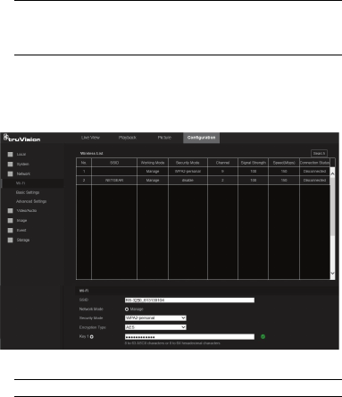
6. Click or tap the Configuration tab.
7. Select Network and then select Wi-Fi on the left menu.
8. Click or tap Search.
9. Click or tap on the Wi-Fi network to be used for the camera in
the Wireless List.
10. Type the Wi-Fi network passphrase in the Key 1 field.
11. Scroll down and click or tap the Save button on the bottom of
the screen.
Note: Do not select Connect in the WPS Section.
12. Repeat steps 9-11 above to add any additional cameras.
13.Connect the setup device to the wireless network selected in
step 9.
Network connection via Wi-Fi is now complete!
16 P/N 466-5303 • REV 07 • ISS 05JAN17 © 2017 United Technologies Corporation. All rights reserved
3. Add cameras to UltraSync
Ensure the proper installation of camera hardware and follow the
instructions in “Add cameras to a Wi-Fi network” on page 15
before adding cameras to UltraSync.
Note: Make sure the camera and UltraSync intrusion panel are on
the same local area network. Applications where the intrusion
panels use cellular only (no Wi-Fi or Ethernet connection) are not
compatible with this camera.
Note: For detailed information on how to set up the UltraSync
app, add locations, and log in as an installer, see the UltraSync
Hub Reference Guide.
1. Using an iOS or Android device, open the UltraSync app and
log in to the site as the installer.
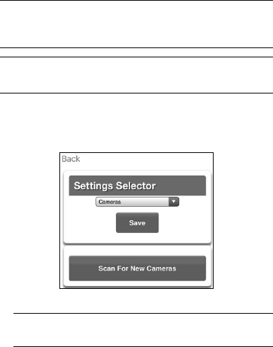
2. Tap the menu icon at the top left of the screen, and then tap
Settings.
3. Tap Cameras in the Settings Selector drop-down.
4. Tap Scan for New Cameras.
5. The “Success!” message appears after a few seconds.
Note: The “Success" message appears after a camera scan
was executed. This does not indicate cameras were added to
the system.
6. The IP and MAC addresses automatically populate for all
cameras on the network. Scroll down to see and verify
connected cameras.
7. Tap Save.
P/N 466-5303 • REV 07 • ISS 05JAN17 © 2017 United Technologies Corporation. All rights reserved 17

Note: The camera may take up to two minutes to finalize
association with the intrusion panel and appear in the cameras
tab.
4. Reboot cameras
1. Launch the TruVision® IP camera configuration browser.
2. Select System and then select Maintenance on the left menu.
3. Select Reboot.
4. Select OK when asked if you want to reboot the unit.
Note: Reboot may take up to two minutes.
5. Go to the Cameras tab in the UltraSync app to verify live
video.
Camera installation is now complete!
Alternative methods of adding cameras
Add cameras via Ethernet with a Windows PC
1. Apply power to the camera using the included power supply.
Note: It may take up to two minutes for the camera to boot up.
2. Connect the camera to a router with an Ethernet cable.
3. Launch TruVision Device Manager.
Note: Install TruVision Device Manager using the included CD
or download it from www.interlogix.com/video.
4. Verify that the camera is found in the main camera selection
window.
5. Select the camera to be configured.
6. In the Password field, type the default password of 1234 and
click Save.
7. In the main camera selection window, select the camera you
would like to configure and double click the IPV4 Address to
launch TruVision IP Camera Configurator in a browser.
Note: The Camera Configurator can also be launched by
typing the camera’s IP address into an internet browser. The
default camera IP address is 192.168.1.70 in a network
without a DHCP server.
8. The TruVision Configurator appears. Enter the credentials
below:
User Name: admin
Password: 1234
9. Tap Network and then tap Basic Settings on the left menu.
18 P/N 466-5303 • REV 07 • ISS 05JAN17 © 2017 United Technologies Corporation. All rights reserved
10. Change LAN settings to the required configuration. If a static
IP Address is required, change the IPv4 Address and IPv4
Subnet Mask to match the router.
a. Change the static IP address to something different than
the default 192.168.1.70 if more than one camera is used
on the network.
b. Click the Test button to ensure that the IP address is not
already assigned to another device in the network.
11. Click Save on the bottom of the screen.
12. Power cycle the camera. See “4. Reboot cameras” on page
18.
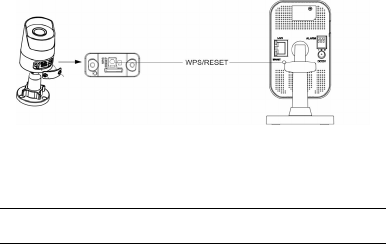
Add cameras via WPS
A WPS-enabled wireless router is required to add a camera using
the WPS function.
1. Press the WPS button on the router.
2. Within 120 seconds of pressing the WPS button on the router,
press the WPS button on the camera for approximately two
seconds. See “Camera description – Bullet Camera” on page
6 and “Camera description – Desktop Camera” on page 7 for
WPS button and LED locations.
The link LED on the camera flashes rapidly to indicate that it
has joined the wireless network.
3. Power cycle the camera. See “4. Reboot cameras” on page
18.
P/N 466-5303 • REV 07 • ISS 05JAN17 © 2017 United Technologies Corporation. All rights reserved 19
UltraSync app basic functions
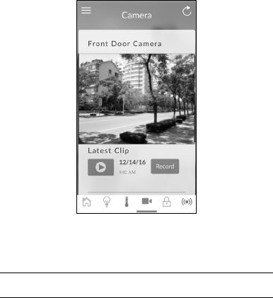
View Live Stream and Latest Clip
1. Tap the Cameras tab on the bottom of the screen. All
available cameras appear.
2. Tap the Play icon underneath the camera name to view a live
feed of a specific camera.
3. Tap the Latest Clip icon to view the last recorded clip from a
specific camera.
Program event triggered camera clips
Cameras can be programmed to automatically record when
selected events occur. This is achieved by creating Automations
(Scenes).
Note: UltraSync installer privileges are required to program event
triggered camera clips.
1. Tap the menu icon at the top left of the screen, and then tap
Settings.
2. Tap the Settings Selector drop-down and then select
Automations (Scenes).
20 P/N 466-5303 • REV 07 • ISS 05JAN17 © 2017 United Technologies Corporation. All rights reserved
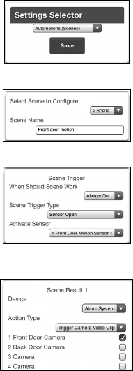
3. Select the Scene to Configure drop-down and type a Scene
Name.
4. Make Scene Trigger selections as shown below (select an
installed sensor from the Activate Sensor drop-down).
5. Make Scene Result selections as shown below (select the
Camera(s) to begin recording when the scene is triggered)
Select Alarm System from the Device drop-down.
Clips are recorded on the Micro SD card installed in the
camera and are linked to events in History.
P/N 466-5303 • REV 07 • ISS 05JAN17 © 2017 United Technologies Corporation. All rights reserved 21
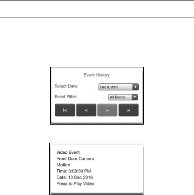
View event triggered clips in History
Note: UltraSync installer privileges are required to view event
triggered camera clips in History.
1. Tap the menu icon at the top left of the screen, and then tap
History.
2. Make Event History selections from the Select Date and
Event Filter drop-downs.
3. Find an event for viewing by tapping the Oldest, Prev, Next,
and Latest buttons.
4. Scroll to the tile containing the video event and tap it to play
video.
Removing cameras from UltraSync
To remove a single camera:
1. Tap the menu icon at the top left of the screen, and then tap
Settings.
2. Tap Cameras under the Settings Selector drop-down.
3. Scroll to the camera to be removed and tap Remove.
4. Click Save.
To remove all cameras:
1. Tap the menu icon at the top left of the screen, and then tap
Advanced.
2. Tap Shorcut.
3. Type SHORTCUT 910.22 and tap OK.
22 P/N 466-5303 • REV 07 • ISS 05JAN17 © 2017 United Technologies Corporation. All rights reserved

Change default camera settings
Default camera settings can be modified using the camera’s
browser configuration interface.
To determine the IP address of the camera to be configured:
Launch the TruVision Device Manager and locate the camera
in the list by device type and/or serial number. The IP address
is listed next to device type.
Launch the UltraSync app and tap the menu icon at the top left
of the screen, tap Settings, and then tap Cameras in the
Settings Selector drop-down.
Note: UltraSync installer privileges are required to view
camera IP addresses.
To access the camera’s browser configuration interface:
Type the IP address obtained using one of the methods above
into a browser (see “Browser requirements” on page 13), and
then enter the login credentials.
In TruVision Device Manager, double-click the IPV4 Address
of the camera in the Device finder tab, and then enter the login
credentials.
TruVision Device Manager
In addition to finding device IP addresses, camera IP settings can
be changed in Device Manager without launching the browser
configuration interface.
TruVision Navigator
UltraSync cameras are compatible with TruVision Navigator video
management system software, which delivers powerful
centralized and remote video management capabilities.
Note: Go to www.interlogix.com/video to download TruVision
Device Manager and TruVision Navigator. See the TruVision
Device Manager User Manual and the TruVision Navigator User
Manual for further information and capabilities.
P/N 466-5303 • REV 07 • ISS 05JAN17 © 2017 United Technologies Corporation. All rights reserved 23
Reset cameras to factory default
If required, a camera can be reset to the factory default settings.
Reset button
1. Remove the camera cover, press and hold the WPS/RESET
button, and then remove power from the camera.
2. Apply power to the camera and continue holding the
WPS/RESET button for 20 seconds.
Camera configurator
1. Launch the camera configuration browser interface.
2. Select System and then select Maintenance on the left menu.
3. Click Restore or Default to restore the default settings.
Note: After restoring the default settings, the IP address is also
restored to the default IP address.
24 P/N 466-5303 • REV 07 • ISS 05JAN17 © 2017 United Technologies Corporation. All rights reserved

Troubleshooting
Troubleshooting/FAQ
1. The camera does not appear in the list of Wi-Fi networks.
Cause
Solution
The camera takes up to 90
seconds to boot up.
It will not show in Wi-Fi
Networks until this is complete.
Another user is currently setting up
the camera using the
recommended method or the
camera has previously been set up
using the recommended method.
Perform a factory reset to
broadcast the camera again.
2. The camera does not add to the UltraSync network when Scan
for Cameras is selected.
Cause
Solution
Older firmware versions do not
support cameras.
Make sure your panel is updated
to the XXXXXX-04 Firmware or
newer.
The camera will not work if the
devices are not on the same
network.
Make sure your camera and
theUltraSync Hub panel are on
the same network.
UltraSync Hub must be using IP
to work with the cameras.
Ensure that the UltraSync Hub
panel is not installed using a
cellular radio only.
Make sure you are not adding
cameras on a network that
already has a high number of
cameras installed on the same
network. This is unusual, but
may be common in testing
environments.
Put UltraSync Hub and the
cameras on their own router and
this should solve the problem.
P/N 466-5303 • REV 07 • ISS 05JAN17 © 2017 United Technologies Corporation. All rights reserved 25

3. The camera was added in the setup process, but the video
doesn’t show in the Cameras tab.
Cause Solution
After completing the setup
process, the camera may take
up to two minutes to full sync
and show in the UltraSync App.
Wait for the process to complete
Make sure the camera is still
connected to the network.
If video still doesn’t appear, go
back into setup and perform the
“Scan for Cameras” function
again.
4. Live Video isn’t giving good quality. It is choppy, shows gray, etc.
Cause Solution
Check to make sure the
camera’s Wi-Fi and/or Ethernet
connection speeds are
adequate (500 Kbps minimum).
If Wi-Fi connection speeds are
poor, we recommend using a Wi-
Fi repeater to increase signal
strength.
The cameras default settings
are set up to work on a strong
home network.
In some cases, low video settings
may be required to achieve a
smooth video. Use the TruVision
browser to change the cameras
video settings.
5. Video Clips take a long time to load.
Cause Solution
The cameras default settings
are set up to have video clips
start playing in the UltraSync
app within 15 seconds (on a
strong network). If default
settings were changed to longer
clip times or higher video
quality, the amount of time
needed to access the clip
increases.
Lower the quality or length of
clips to shorten load times.
26 P/N 466-5303 • REV 07 • ISS 05JAN17 © 2017 United Technologies Corporation. All rights reserved

Specifications
UltraSync Wi-Fi IP Bullet Camera
Electrical
Voltage input 12 VDC, PoE (IEEE 802.3af)
Power consumption Max. 5.8W
Wi-Fi parameters
Wi-Fi standard IEEE802.11b/g/n
Frequency range
Communication
bandwidth
Support 20/40 MHz
Security 64/128-bit WEP, WPA/WPA2,
WPA-PSK/WPA2-PSK, WPS
Transmission rate 11b: 11Mbps, 11g: 54Mbps,
11n: up to 150Mbps
Transmission range Up to 50m
Varies depending on the actual
working environment.
General
Dimensions 70×157×62 mm (2.8×6.1×2.4 in.)
Weight 500g (1.1 lb)
P/N 466-5303 • REV 07 • ISS 05JAN17 © 2017 United Technologies Corporation. All rights reserved 27
802.11 b/g/n(HT20): 2412MHz-2462MHz
802.11 n(HT40): 2422MHz-2452MHz

UltraSync Wi-Fi IP Desktop Camera
Electrical
Voltage input DC12V±10%, PoE (IEEE 802.3af)
Power consumption Max. 4.5W
Wi-Fi parameters
Wi-Fi standard IEEE802.11b/g/n
Frequency range
Communication
bandwidth
Support 20/40 MHz
Security 64/128-bit WEP, WPA/WPA2,
WPA-PSK/WPA2-PSK, WPS
Transmission rate 11b: 11Mbps, 11g: 54Mbps,
11n: 150Mbps
Transmission range Up to 50m
Varies depending on the actual
working environment.
General
Dimensions 70×72.3×133.3 mm (2.8×2.8×5.2 in.)
Weight 400g (0.88 lb)
28 P/N 466-5303 • REV 07 • ISS 05JAN17 © 2017 United Technologies Corporation. All rights reserved
802.11 b/g/n(HT20): 2412MHz-2462MHz
802.11 n(HT40): 2422MHz-2452MHz
Copyright © 2017 United Technologies Corporation,
Interlogix is part of UTC Climate, Controls &
Security, a unit of United Technologies
Corporation. All rights reserved.
Trademarks and
patents
Trade names used in this document may be
trademarks or registered trademarks of the
manufacturers or vendors of the respective
products.
Manufacturer Interlogix
2955 Red Hill Avenue, Costa Mesa, CA
92626-5923, USA
Authorized EU manufacturing representative:
UTC Fire & Security B.V.
Kelvinstraat 7, 6003 DH Weert, The Netherlands
Certification
FCC compliance Class B: This equipment has been tested and
found to comply with the limits for a Class B digital
device, pursuant to part 15 of the FCC Rules.
These limits are designed to provide reasonable
protection against harmful interference when the
equipment is operated in a commercial
environment. This equipment generates, uses, and
can radiate radio frequency energy and, if not
installed and used in accordance with the
instruction manual, may cause harmful
interference to radio communications. Operation of
this equipment in a residential area is likely to
cause harmful interference in which case the user
will be required to correct the interference at his
own expense.
FCC conditions This device complies with Part 15 of the FCC
Rules. Operation is subject to the following two
conditions:
(1) This device may not cause harmful
interference.
(2) This Device must accept any interference
received, including interference that may cause
undesired operation.
Federal Communication Commission (FCC)
Radiation Exposure Statement
This equipment complies with FCC radiation
exposure set forth for an uncontrolled
environment. In order to avoid the possibility of
exceeding the FCC radio frequency exposure
P/N 466-5303 • REV 07 • ISS 05JAN17 © 2017 United Technologies Corporation. All rights reserved 29
limits, human proximity to the antenna shall not be
less than 20 cm (8 inches) during normal
operation.
CAUTION: Changes or modifications not expressly
approved by UTC for compliance could void the
user’s authority to operate the equipment.
RS-3230/RS-3231/TVQ-8101 COMPLIES WITH
FCC PART C, FCC ID: 2AENJ-RS323x
RS-3250/RS-3251/TVB-8101 COMPLIES WITH
FCC PART C, FCC ID: 2AENJ-RS325x
ACMA compliance Notice! This is a Class A product. In a domestic
environment this product may cause radio
interference in which case the user may be
required to take adequate measures.
Canada This Class B digital apparatus complies with CAN
ICES-003 (B)/NMB-3 (B).
Cet appareil numérique de la classe B est
conforme à la norme CAN ICES-003
(B)/NMB-3 (B).
Canadian Compliance
This Class B digital apparatus meets all
requirements of the Canadian Interference
Causing Equipment Regulations. Cet appareil
numérique de la classe B respects toutes les
exigences du Règlement sur le matériel brouilleur
du Canada.
Canada - Industry Canada (IC)
The wireless radio of this device complies with
RSS 247 and RSS 102 of Industry Canada.
This Class B digital device complies with Canadian
ICES-003 (NMB-003).
Cet appareil numérique de la classe B respects
toutes les exigences du Règlement sur le matériel
brouilleur du Canada.
This device complies with Industry Canada’s
licence-exempt RSSs. Operation is subject to the
following two conditions:
(1) This device may not cause interference; and
(2) This device must accept any interference,
including interference that may cause undesired
operation of the device.
Le présent appareil est conforme aux CNR
d'Industrie Canada applicables aux appareils radio
exempts de licence. L'exploitation est autorisée
aux deux conditions suivantes :
30 P/N 466-5303 • REV 07 • ISS 05JAN17 © 2017 United Technologies Corporation. All rights reserved
(1) l'appareil ne doit pas produire de brouillage, et
(2) l'utilisateur de l'appareil doit accepter tout
brouillage radioélectrique subi, même si le
brouillage est susceptible d'en compromettre le
fonctionnement.
RS-3230/RS-3231/TVQ-8101 complies with IC
requirements, IC: 20201-RS323x.
RS-3250/RS-3251/TVB-8101 complies with IC
requirements, IC: 20201-RS325x.
This radio transmitter (IC: 20201-RS3130) has
been approved by Industry Canada to operate with
the antenna types listed below with the maximum
permissible gain indicated. Antenna types not
included in this list, having a gain greater than the
maximum gain indicated for that type, are strictly
prohibited for use with this device.
Internal (Default): 2.4dBi directional antenna
Le présent émetteur radio (IC: 20201-
RS31130) a été approuvé par Industrie
Canada pour
fonctionner avec les types d'antenne énumérés ci-
dessous et ayant un gain admissible maximal et
l'impédance requise pour chaque type d'antenne.
Les types d'antenne non inclus dans cette liste, ou
dont le gain est supérieur au gain maximal indiqué,
sont strictement interdits pour l'exploitation de
l'émetteur.
intégré 2.4dBi antenne
European Union
directives
This product and - if applicable - the supplied
accessories too are marked with "CE" and comply
therefore with the applicable harmonized
European standards listed under the EMC
Directive 2014/30/EU, the RoHS Directive
2011/65/EU and Directive:2014/35/EU (LVD).
R&TTE Compliance Statement
This equipment complies with all the requirements
of DIRECTIVE 1999/5/CE OF THE EUROPEAN
PARLIAMENT AND THE COUNCIL OF 9 March
1999 on radio equipment and telecommunication
terminal Equipment and the mutual recognition of
their conformity (R&TTE).
P/N 466-5303 • REV 07 • ISS 05JAN17 © 2017 United Technologies Corporation. All rights reserved 31
This equipm should be installed and operated with
a minimum distance 20cm between the radiator
and your body
Cet équipement doit être installé et utilisé à une
distance minimale de 20 cm entre le radiateur
et votre corps
must therefore be allowed at all times to ensure
the safe use of the equipment.
Installation must at all times conform to local
regulations.
2012/19/EU (WEEE directive): Products marked
with this symbol cannot be disposed of as
unsorted municipal waste in the European Union.
For proper recycling, return this product to your
local supplier upon the purchase of equivalent new
equipment, or dispose of it at designated collection
points. For more information see:
www.recyclethis.info.
2013/56/EU (battery directive): This product
contains a battery that cannot be disposed of as
unsorted municipal waste in the European Union.
See the product documentation for specific battery
information. The battery is marked with this
symbol, which may include lettering to indicate
cadmium (Cd), lead (Pb), or mercury (Hg). For
proper recycling, return the battery to your supplier
or to a designated collection point. For more
information see: www.recyclethis.info.
Contact information For contact information, see www.interlogix.com or
www.utcfssecurityproducts.eu.
32 P/N 466-5303 • REV 07 • ISS 05JAN17 © 2017 United Technologies Corporation. All rights reserved
Safety
This equipment is designed with the utmost care
for the safety of those who install and use it.
However, special attention must be paid to the
dangers of electric shock and static electricity
when working with electrical equipment. All
guidelines of this and of the computer manufacture

Annex 3 B and A Wideband Data Transmission systems 2400.0-2483.5 MHz:
Country Restriction Reasons/remarks
Norway Implemented This subsection does not apply for the
geographical area within a radius of 20 km
from the centre of Ny-Ålesund.
Italy Implemented The public use is subject to general
authorization by the respective service
provider.
Russian
Federation
Limited
implementation
1. SRD with FHSS modulation
1.1. Maximum 2.5 mW e.i.r.p.
1.2. Maximum 100 mW e.i.r.p. Permitted for
use SRD for outdoor applications without
restriction on installation height only for
purposes of gathering telemetry information
for automated monitoring and resources
accounting systems. Permitted to use SRD for
other purposes for outdoor applications only
when the installation height is not exceeding
10 m above the ground surface. 1.3 maximum
100 mW e.i.r.p. indoor applications.
2. SRD with DSSS and other than FHSS
wideband modulation
2.1. Maximum mean e.i.r.p. density is
2 mW/MHz. Maximum 100 mW e.i.r.p.
2.2. Maximum mean e.i.r.p. density is
20 mW/MHz. Maximum 100 mW e.i.r.p. It is
permitted to use SRD for outdoor applications
only for purposes of gathering telemetry
information for automated monitoring and
resources accounting systems or security
systems.
2.3. Maximum mean e.i.r.p. density is
10 mW/MHz. Maximum 100 mW e.i.r.p. indoor
applications.
Ukraine Limited
implementation
e.i.r.p. ≤100 mW with built-in antenna with
amplification factor up to 6 dBi.
P/N 466-5303 • REV 07 • ISS 05JAN17 © 2017 United Technologies Corporation. All rights reserved 33
PRODUCT WARNINGS
A PROPERLY INSTALLED AND MAINTAINED ALARM/SECURITY SYSTEM MAY ONLY
REDUCE THE RISK OF EVENTS SUCH AS BREAK-INS, BURGLARY, ROBBERY OR
FIRE; IT IS NOT INSURANCE OR A GUARANTEE THAT SUCH EVENTS WILL NOT
OCCUR, THAT ADEQUATE WARNING OR PROTECTION WILL BE PROVIDED, OR
THAT THERE WILL BE NO DEATH, PERSONAL INJURY, AND/OR PROPERTY
DAMAGE AS A RESULT.
WHILE INTERLOGIX UNDERTAKES TO REDUCE THE PROBABILITY THAT A THIRD
PARTY MAY HACK, COMPROMISE OR CIRCUMVENT ITS SECURITY PRODUCTS OR
RELATED SOFTWARE, ANY SECURITY PRODUCT OR SOFTWARE
MANUFACTURED, SOLD OR LICENSED BY INTERLOGIX, MAY STILL BE HACKED,
COMPROMISED AND/OR CIRCUMVENTED.
INTERLOGIX DOES NOT ENCRYPT COMMUNICATIONS BETWEEN ITS ALARM OR
SECURITY PANELS AND THEIR OUTPUTS/INPUTS INCLUDING, BUT NOT LIMITED
TO, SENSORS OR DETECTORS UNLESS REQUIRED BY APPLICABLE LAW. AS A
RESULT THESE COMMUNICATIONS MAY BE INTERCEPTED AND COULD BE USED
TO CIRCUMVENT YOUR ALARM/SECURITY SYSTEM.
WARRANTY DISCLAIMERS
INTERLOGIX HEREBY DISCLAIMS ALL WARRANTIES AND REPRESENTATIONS,
WHETHER EXPRESS, IMPLIED, STATUTORY OR OTHERWISE INCLUDING (BUT NOT
LIMITED TO) ANY WARRANTIES OF MERCHANTABILITY OR FITNESS FOR A
PARTICULAR PURPOSE WITH RESPECT TO ITS SECURITY PRODUCTS AND
RELATED SOFTWARE. INTERLOGIX FURTHER DISCLAIMS ANY OTHER IMPLIED
WARRANTY UNDER THE UNIFORM COMPUTER INFORMATION TRANSACTIONS
ACT OR SIMILAR LAW AS ENACTED BY ANY STATE.
(USA only) SOME STATES DO NOT ALLOW THE EXCLUSION OF IMPLIED
WARRANTIES, SO THE ABOVE EXCLUSION MAY NOT APPLY TO YOU. THIS
WARRANTY GIVES YOU SPECIFIC LEGAL RIGHTS AND YOU MAY ALSO HAVE
OTHER LEGAL RIGHTS THAT VARY FROM STATE TO STATE.
INTERLOGIX MAKES NO REPRESENTATION, WARRANTY, COVENANT OR PROMISE
THAT ITS SECURITY PRODUCTS AND/OR RELATED SOFTWARE (I) WILL NOT BE
HACKED, COMPROMISED AND/OR CIRCUMVENTED; (II) WILL PREVENT, OR
PROVIDE ADEQUATE WARNING OR PROTECTION FROM, BREAK-INS, BURGLARY,
ROBBERY, FIRE; OR (III) WILL WORK PROPERLY IN ALL ENVIRONMENTS AND
APPLICATIONS.
34 P/N 466-5303 • REV 07 • ISS 05JAN17 © 2017 United Technologies Corporation. All rights reserved