UTC Fire and Security ATS111X Keypad with proximity reader transmitter User Manual 1048520A AL 111X I I p65
UTC Fire & Security B.V. Keypad with proximity reader transmitter 1048520A AL 111X I I p65
UserManual.wiki
>
UTC Fire and Security
>
ATS111X User Manual
Installation Instructions
Navigation menu
Upload a User Manual
Namespaces
Wiki Guide
HTML
PDF
Info
Views
User Manual
Discussion / Help
Navigation
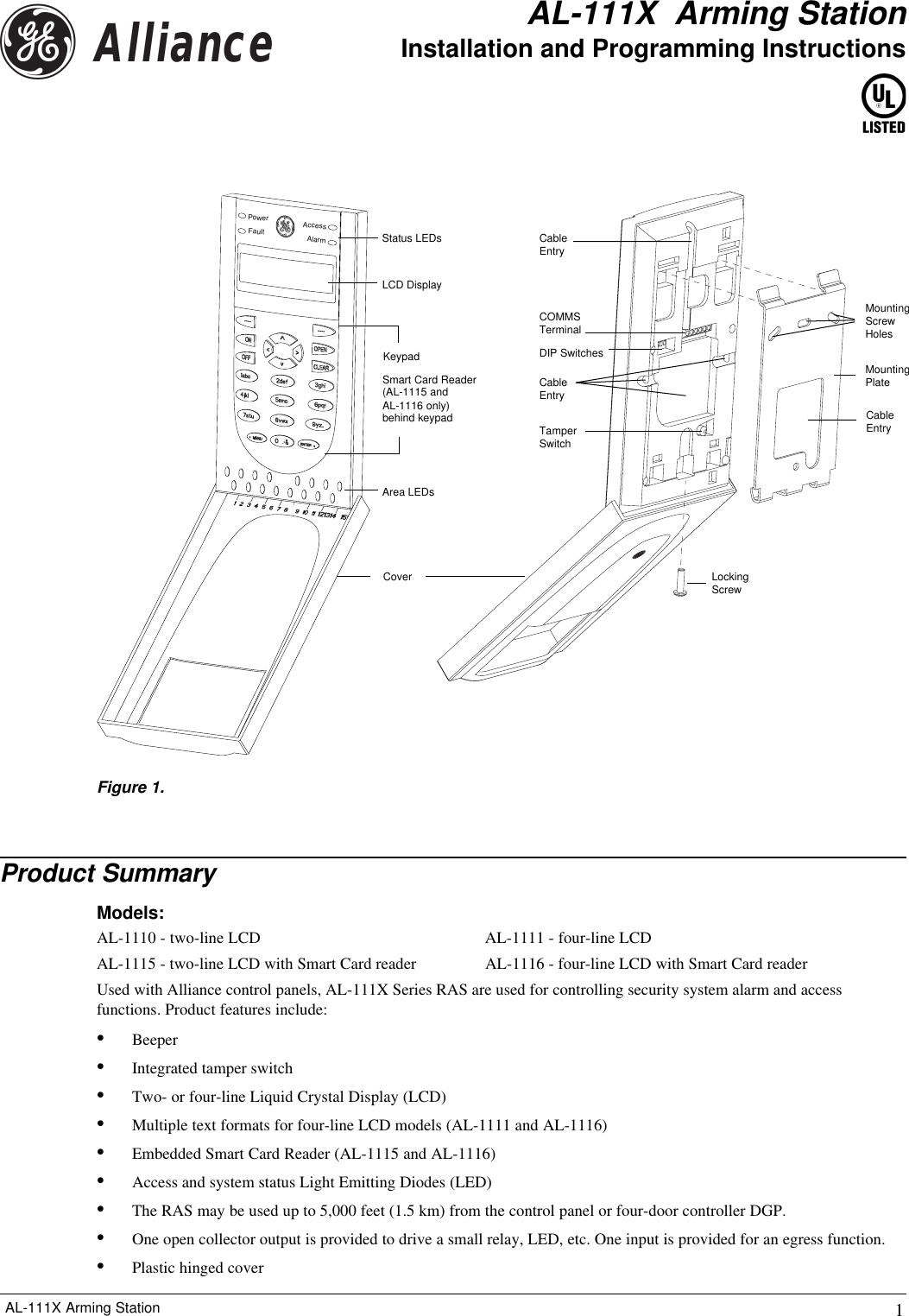
![4 AL-111X Arming StationKeyboard Backlight and Night LightThe default keyboard backlight and night light settings are as follows:•Keyboard backlight on (bright) for approximately 4 1/4 minutes following a key press.•Night light on (dim).These functions can be changed from the RAS menu. See Menu Options.LCD ContrastThe LCD contrast may be adjusted by pressing and holdingthe [*MENU] key while momemtarily pressing the [UP] or[DOWN] keys to change the display contrast. The defaultsetting is 12.LCD BacklightThe LCD backlight illuminates for 30 seconds following a key press.Beeper ToneThe beeper tone may be adjusted by pressing and holding the [CLEAR] key while momentarily pressing the [UP] or[DOWN] keys to change the beeper tone. The default setting is 16.LCD Text FormatAL- 1111 and AL-1116 RAS have a 4 line x 16 character LCD and may display text in the following three alternativeformats:•Format 1 (default) wraps text using hyphens when a word is broken onto the next line.•Format 2 wraps text without hyphens when a word is broken onto the next line.•Format 3 wraps text to the next line without breaking words.To change formats, press and hold the [0] (zero) key while momentarily pressing the [UP] or [DOWN] keys. This option isnot available on AL-1110 or AL-1115 RAS with 2 line x 16 character LCD.Card Reader (AL-1115 and AL-1116 only)AL-1115 and AL-1116 RAS are fitted with a Smart Card reader which uses the address of the RAS to communicate withthe panel and so does not need to have its own System BUS address.The Smart Card reader is located behind the keypad with the number 2 key being the approximate center (see Figure 1). Thesensitivity of the reader is dependent on the environment on which it is mounted (large metal surfaces will reduce thereader’s sensitivity).Power UpUpon initial power up, the beeper will sound two beeps indicating that the internal non-volatile memory is OK. All of thearea LEDs may illuminate, indicating that the system is armed. All area must be disarmed in order to enable access to theinstaller programming menu options. Status LED IndicationsAL-111X RAS have four status LEDs above the LCD panel (see Figure 1):•Power - The Green LED illuminates when the control panel is powered by the AC supply.•Fault - The Yellow LED illuminates to indicate detection of a system fault.•Access - The Blue LED flashes when access to an area assigned to the RAS is granted. It also flashes once when acard is badged at an AL-1115 or AL-1116 (subject to Valid Card Flashing Programming).•Alarm - The Red LED illuminates when there is a system tamper or an area assigned to the RAS is in alarm state. Thearea may be identified by viewing the 16 area LEDs visible when the RAS cover is open or removed. Area LED IndicationsWhen the RAS cover is opened or removed, 16 red area LEDs are visible at the bottom of the RAS (see Figure 1). EachLED represents an area, and the indications are as follows:•The LED illuminates when its corresponding area is armed.•The LED flashes slowly when a fault is detected in its corresponding area.•The LED flashes quickly when an alarm occurs in its corresponding area. Operating FeaturesUP KeyDOWN Key](https://usermanual.wiki/UTC-Fire-and-Security/ATS111X/User-Guide-423020-Page-4.png)
![5 AL-111X Arming StationIntroductionThe AL-111X Series has a number of options that are programmable at the time of installation to help integrate the keypadinto the local environment.In particular, the AL-1115 and AL-1116 RAS are fitted with a Smart Card reader. If used in the default “secure” mode, thereader must be configured via a reader configuration card before it can be used. The reader configuration card must beprogrammed using the Alliance software management application in conjunction with a TS0870P Smart Card Programmer.The setting for the Smart Card reader can be changed to “unsecured” via menu option 7-Security Mode, in which case thecard’s unique serial number is used. Unsecured mode requires the use of an expanded memory (IUM-equipped) system.Accessing the RAS Main MenuThe programming menu of the AL-111X Series RAS is structured into two sections:•Menus 1 to 6 are common to all AL-111X Series RAS.•Menus 7 to 12 apply only to AL-1115 and AL-1116 RAS (with Smart Card reader).The AL-111X Series menu system works in the same manner as all other remote units on the System BUS.1. With all areas disarmed, press [*MENU], [installer code], [ENTER#].2. Press [19], [ENTER#], [*MENU], [28], [ENTER#].3. Press [2], [ENTER#] to access the RAS menu.4. Press [RAS address], [ENTER#].5. You are now in the RAS main menu, and the text displays similar to the following:GE Security, RAS111x.Vxx0-Exit, Menu:_(111x is the product name and Vxx is the firmware revision number)Navigating the RAS Main MenuThe navigation sequence varies depending on where you are in the menu hierarchy. The main menu is used in the followingmanner:•Press [ENTER#] to scroll forward through the main menu options. Press [*MENU] to scroll backward through themain menu options.•Each menu option has an associated option number. To select a menu option and open its sub-menu, press [optionnumber], [ENTER#].•Press [0, -&], to exit the RAS main menu.Navigating the RAS Sub-MenusSub-menus typically offer a choice between two options, a default setting and an alternative setting. Sub-menus are used inthe following manner:•Press [ENTER#] to accept the currently displayed setting and to return to the main menu.•Press [*MENU] to select the alternative setting. Programming](https://usermanual.wiki/UTC-Fire-and-Security/ATS111X/User-Guide-423020-Page-5.png)