UTStarcom Korea Technologies UTS-800FSU Wireless Local Loop Fixed Subscriber Unit User Manual Fixed Subscriber Unit
UTStarcom Korea Technologies Ltd. Wireless Local Loop Fixed Subscriber Unit Fixed Subscriber Unit
Contents
- 1. FSU Manual Cover
- 2. FSU Manual Front
- 3. FSU Manual
FSU Manual

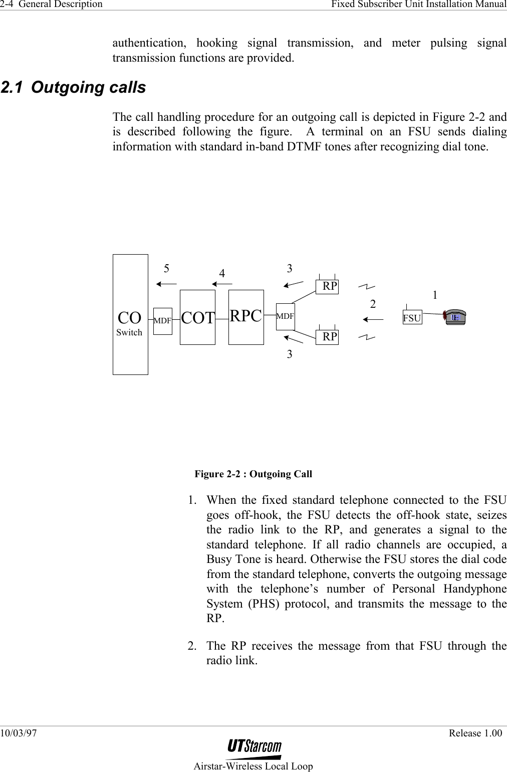
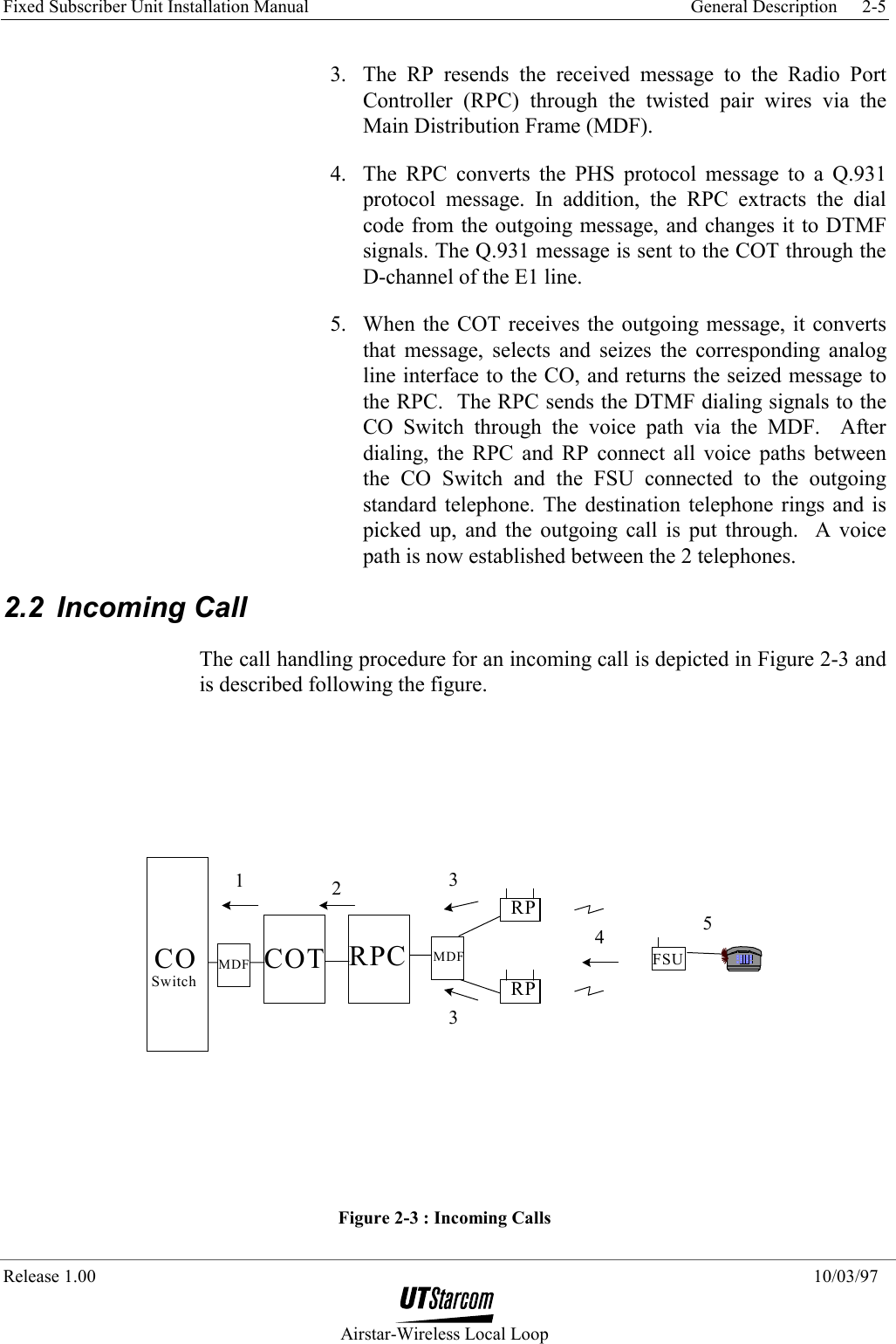
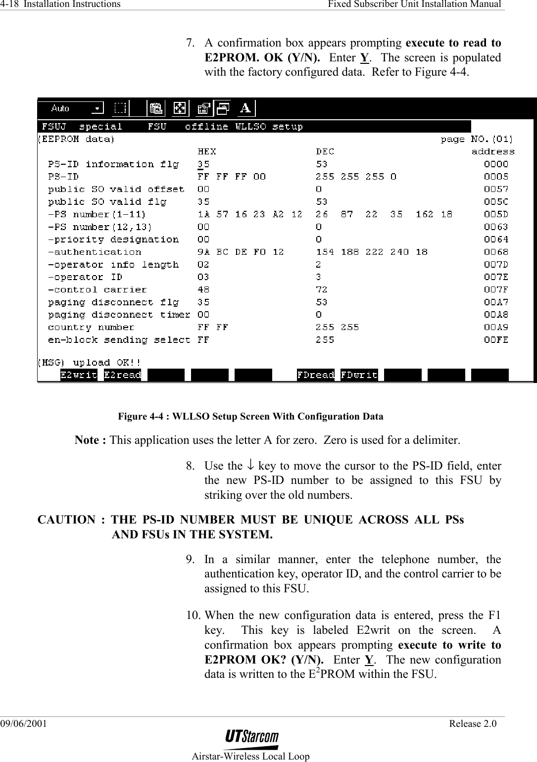
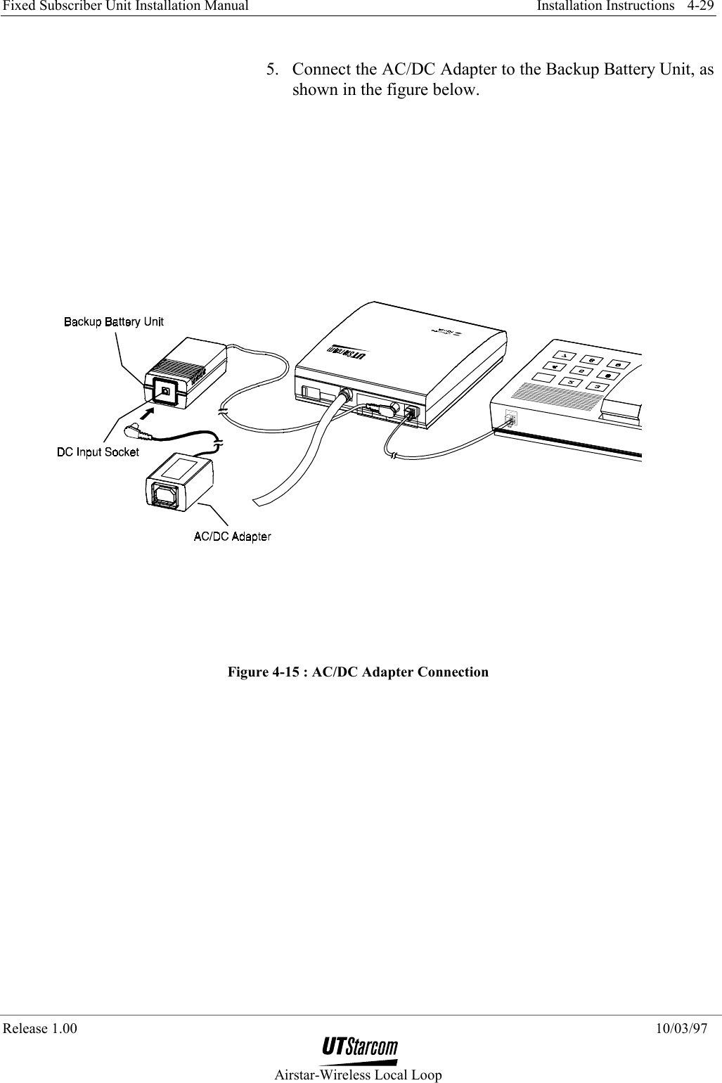
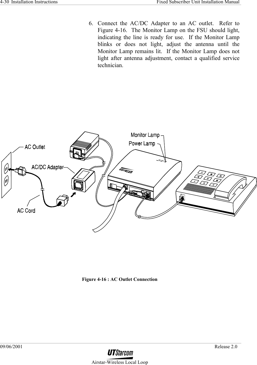
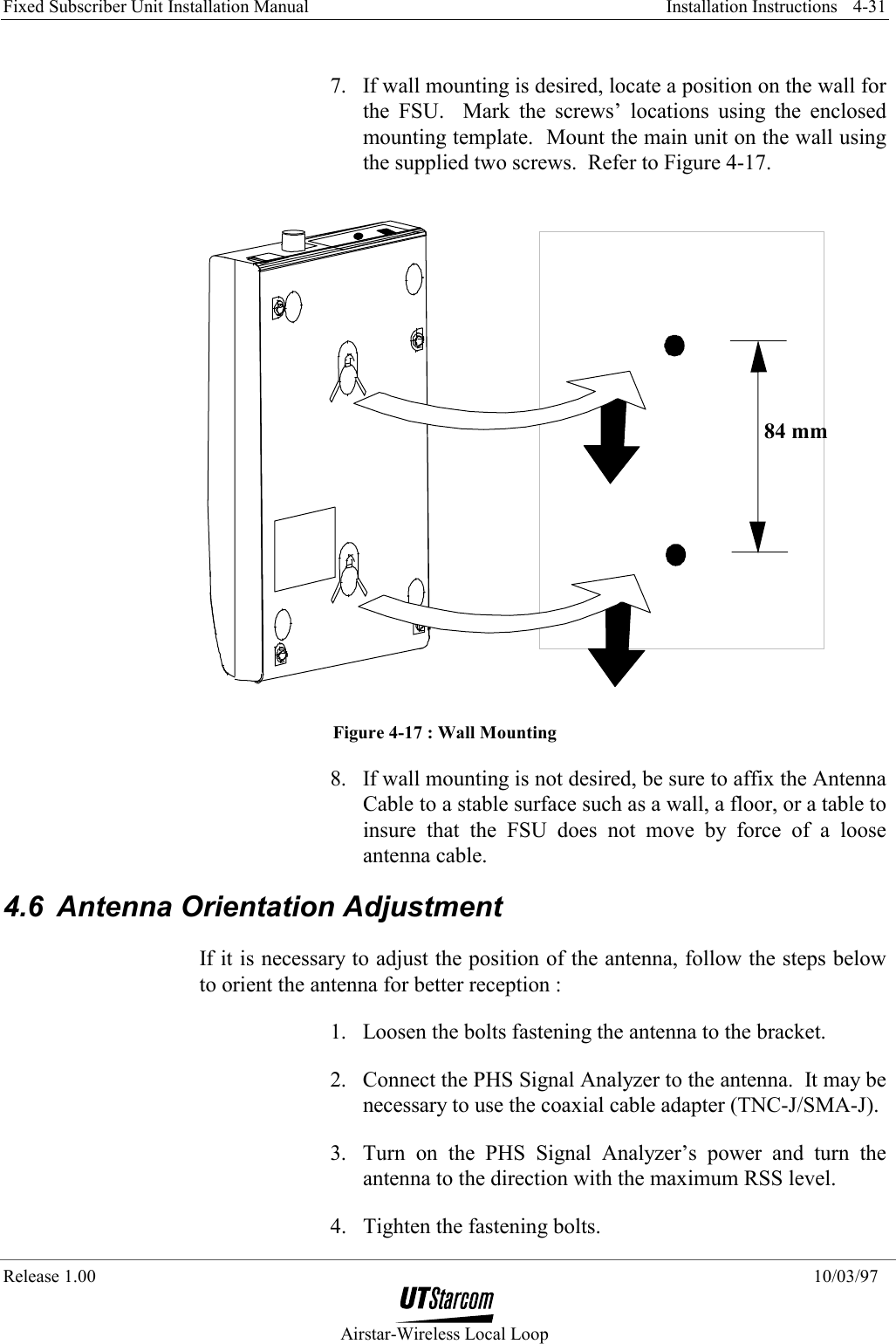
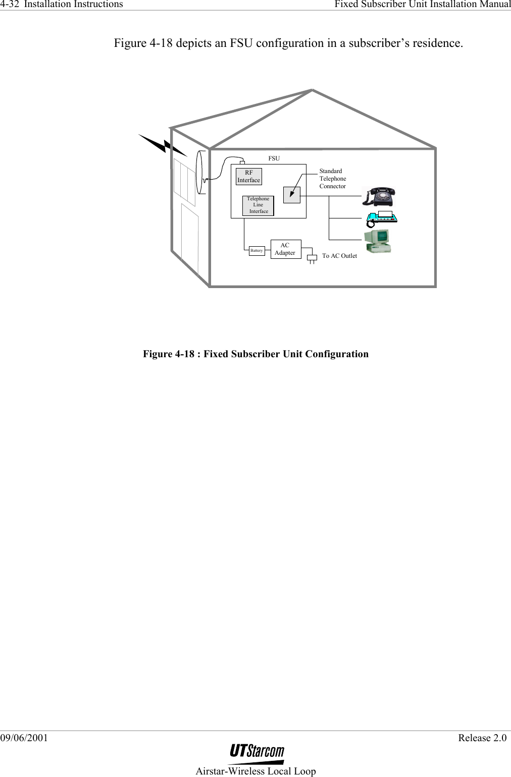
![Fixed Subscriber Unit Installation Manual Installation Instructions Release 1.00 10/03/97 Airstar-Wireless Local Loop 4-15 • Phillips (or Plus) screwdriver • Electric drill • Step ladder • AC power extension cord Special Tools for Cable Termination: • Cable stripper • Crimper Antenna Orientation Instruments: • Map • Compass • Binoculars Measuring Receiver or Equivalent: • Measuring receiver • Memory card • AC adapter • Adapter (3-poles→2-poles conversion) • Coaxial cable adapter TNC-J/SM-J (optional) • 5 meters of coaxial cable (optional) • Power cable 4.2 FSU Configuration Instructions The FSU’s configuration data consists of dozens of parameters that are loaded at the factory. When a subscriber requests service, four of these parameters must be re-configured. Re-configuring the FSU entails writing the following information to the FSU’s Electrically Erasable Programmable Read Only Memory (E2PROM): • PS-ID • Telephone number [PS Number (1-11)]](https://usermanual.wiki/UTStarcom-Korea-Technologies/UTS-800FSU.FSU-Manual/User-Guide-173435-Page-15.png)