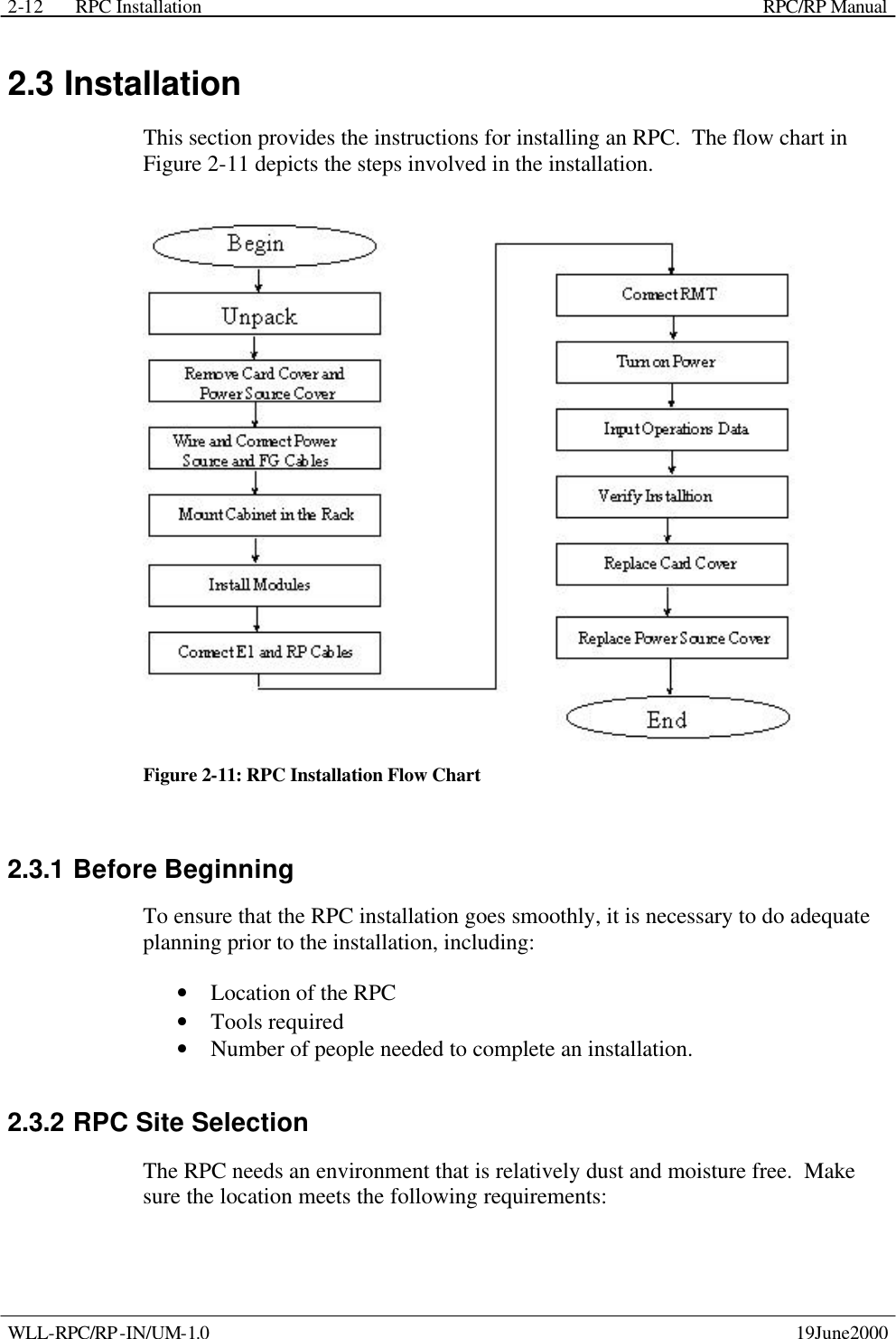
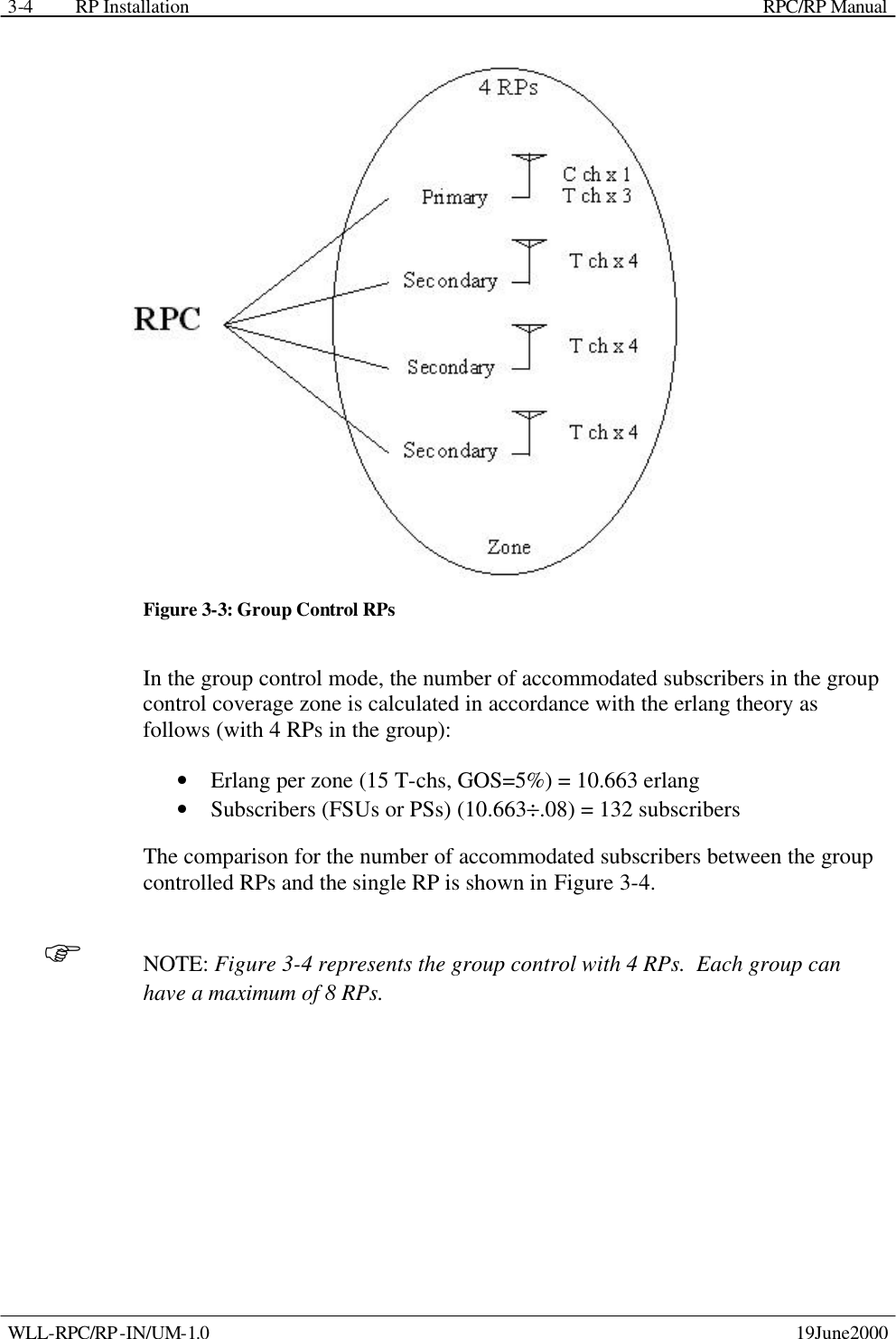
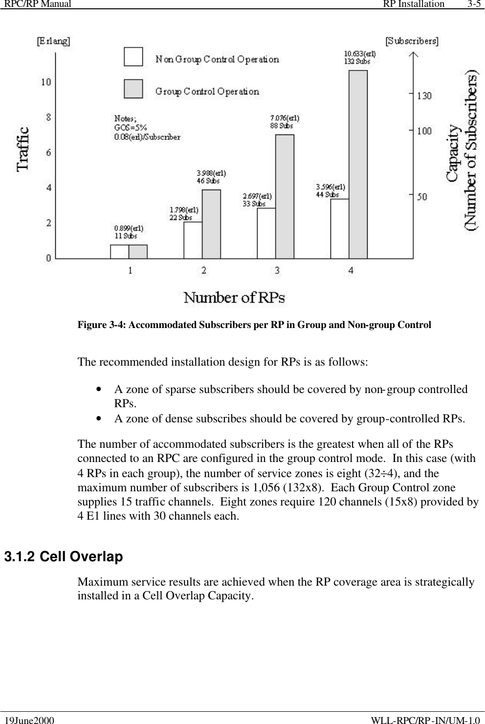
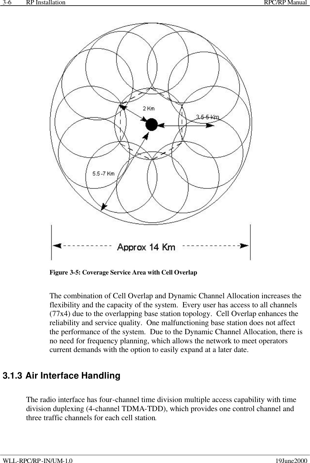
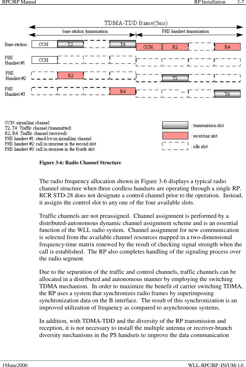
UTStarcom Korea Technologies UTS-EA1H75B Wireless Local Loop Fixed Terminal User Manual Cover
UTStarcom Korea Technologies Ltd. Wireless Local Loop Fixed Terminal Cover
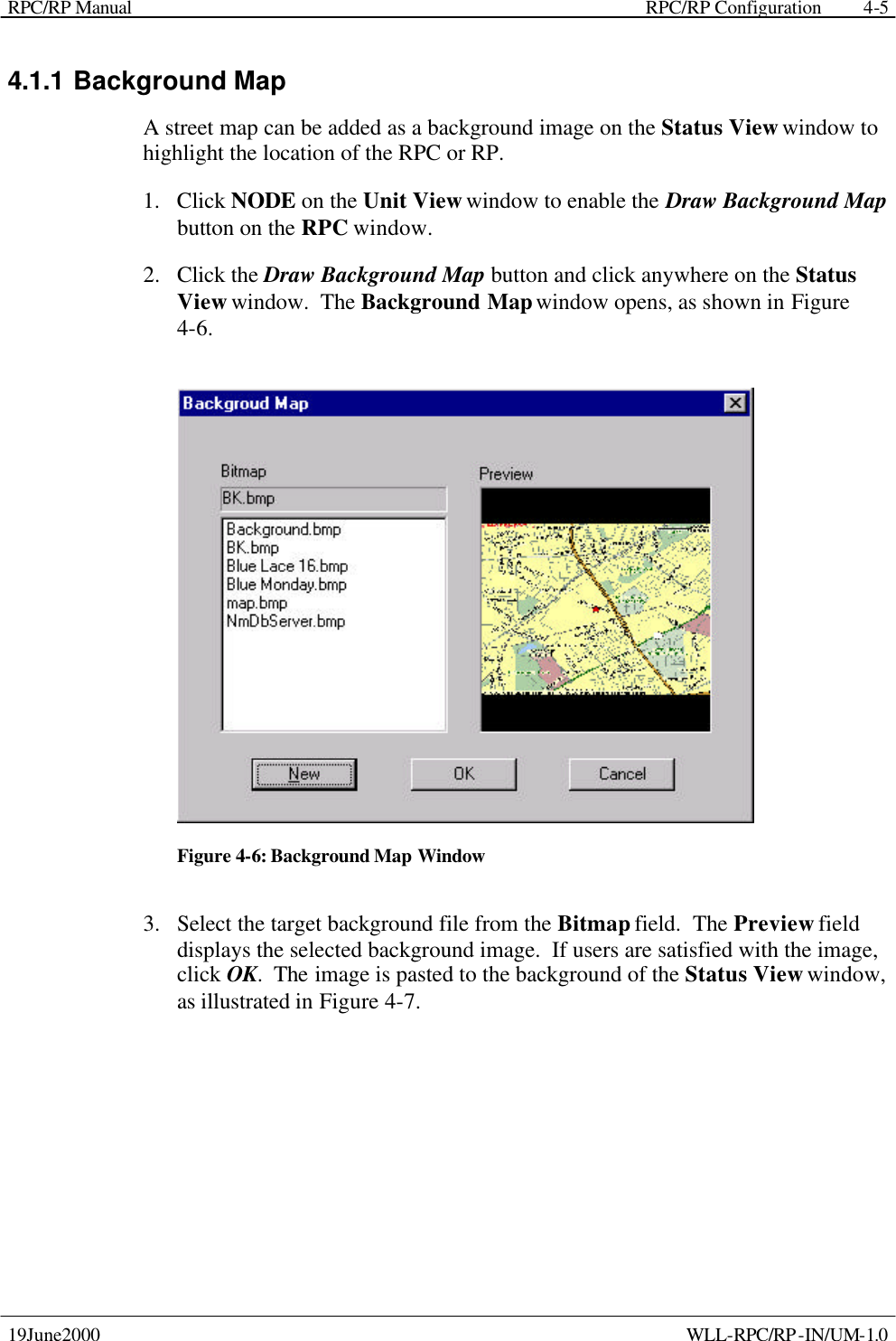
Contents
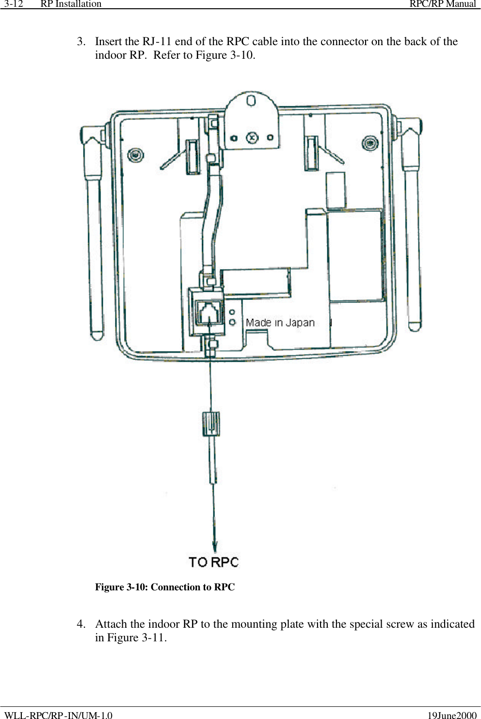
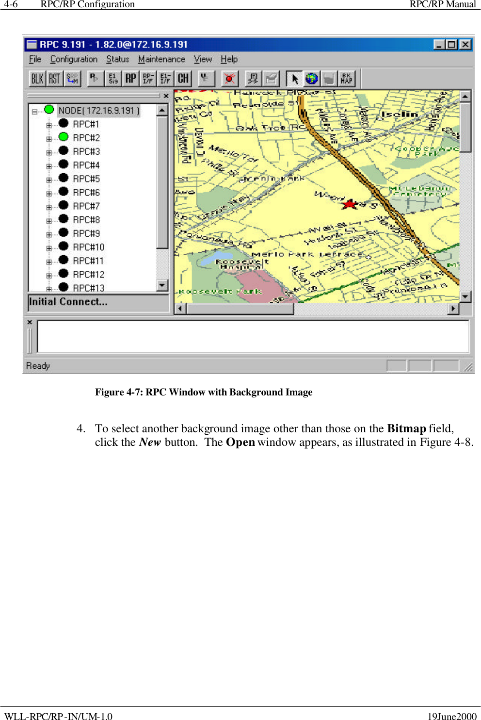
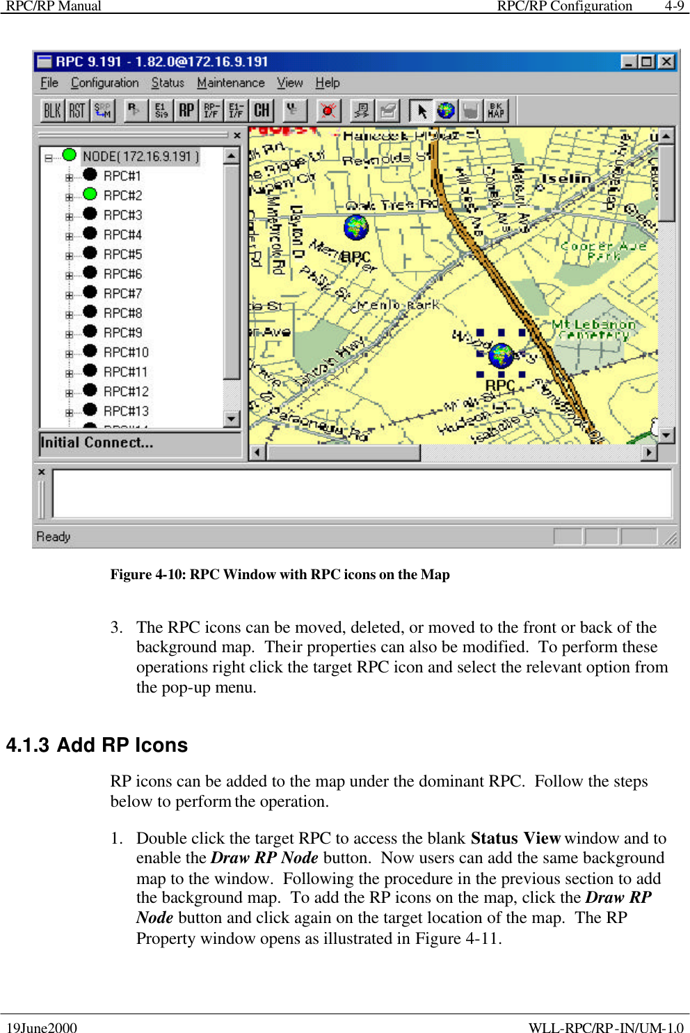
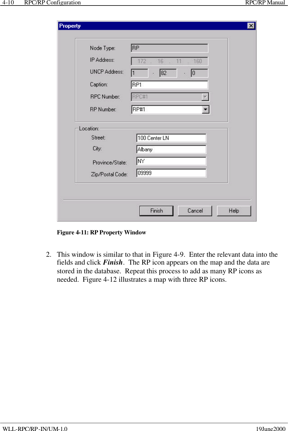
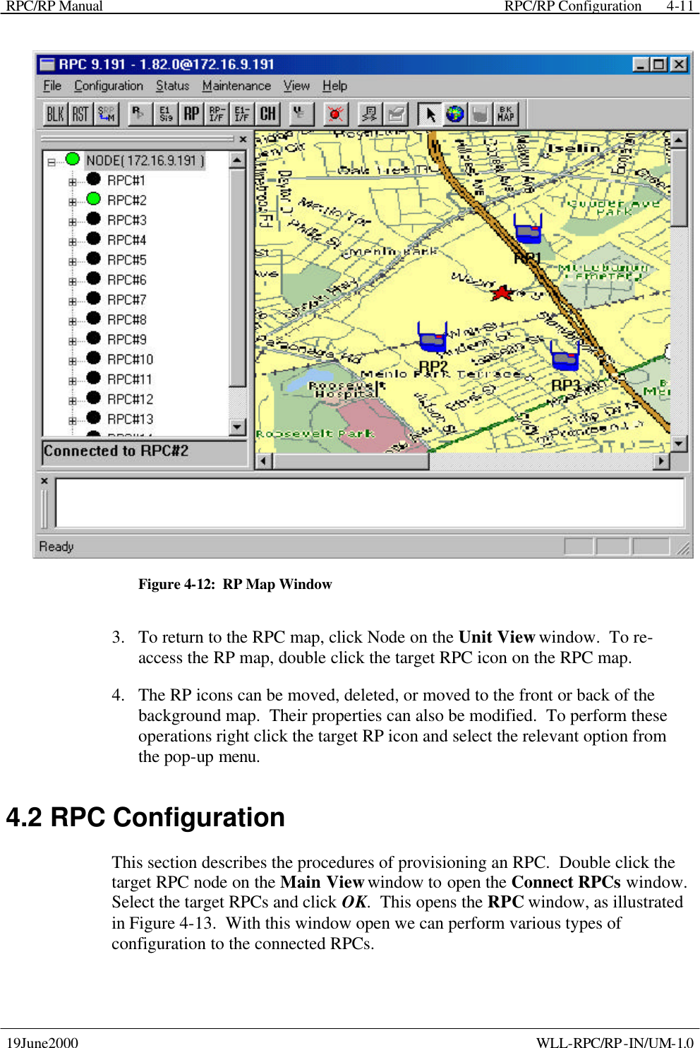
- 1. Users Manual 1 to 75
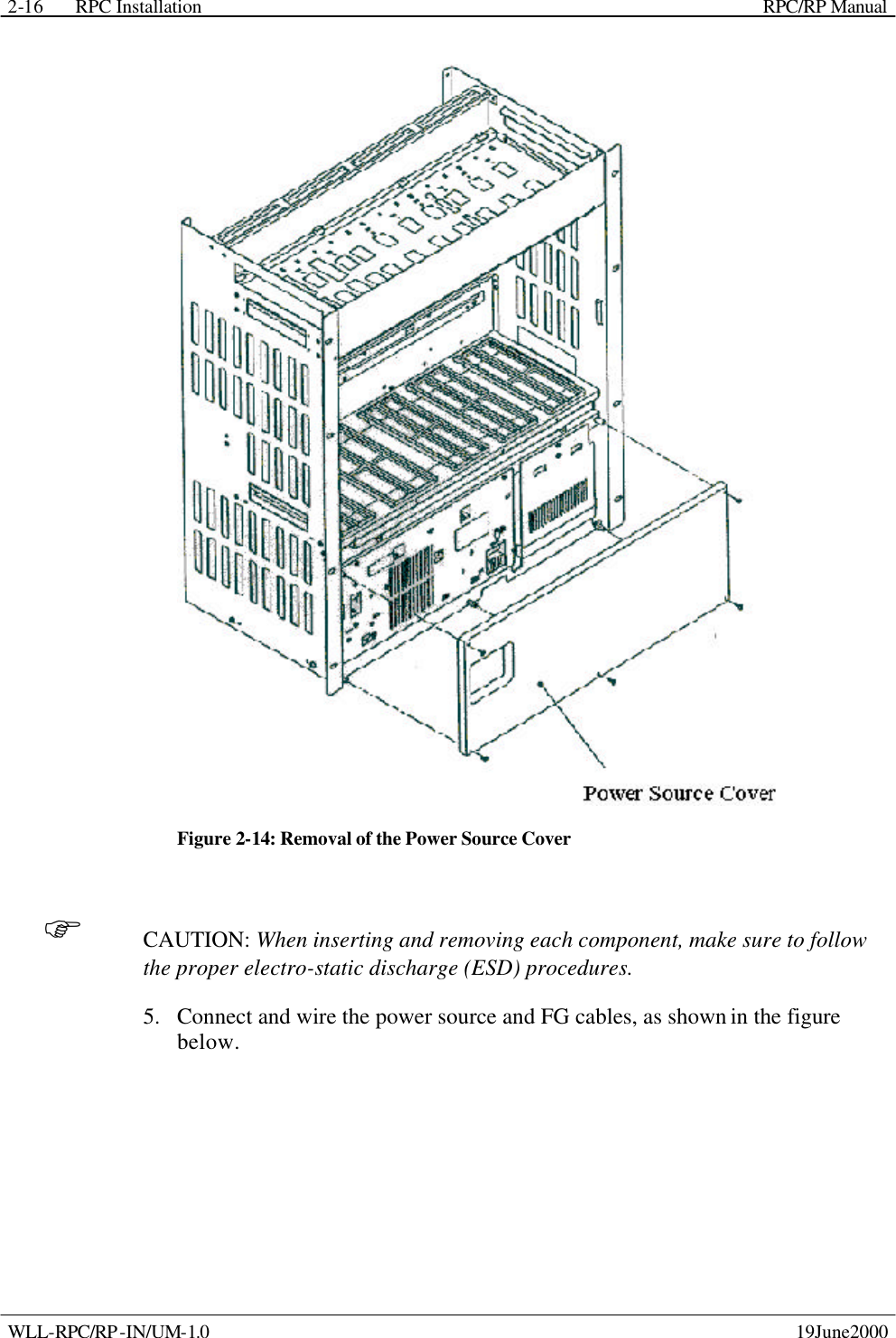
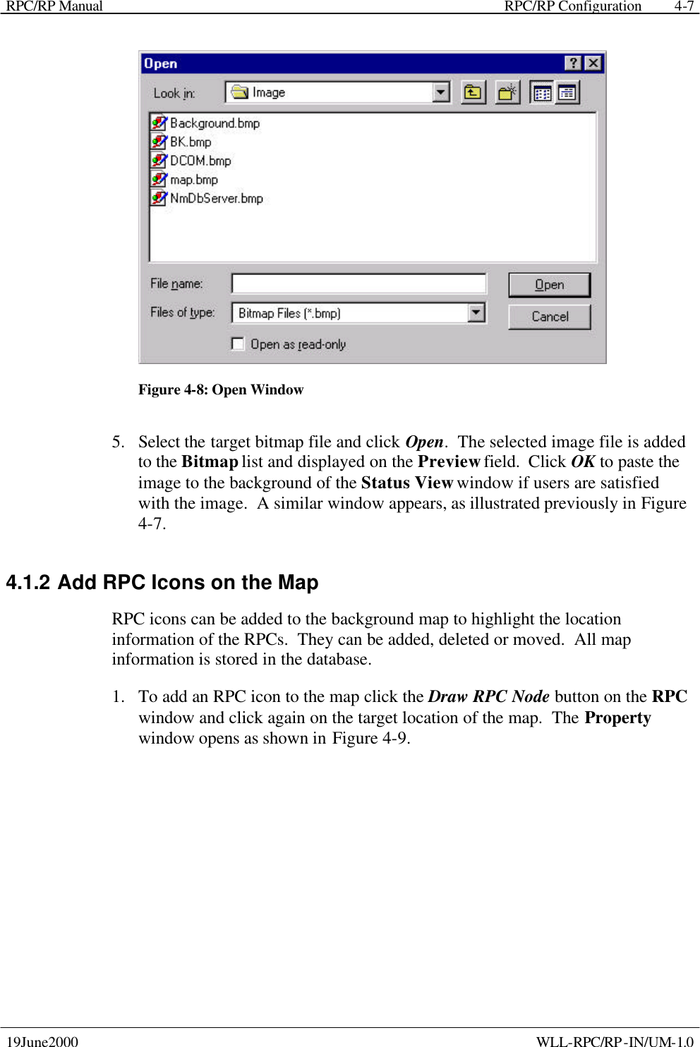
- 2. Manual 75 to 152
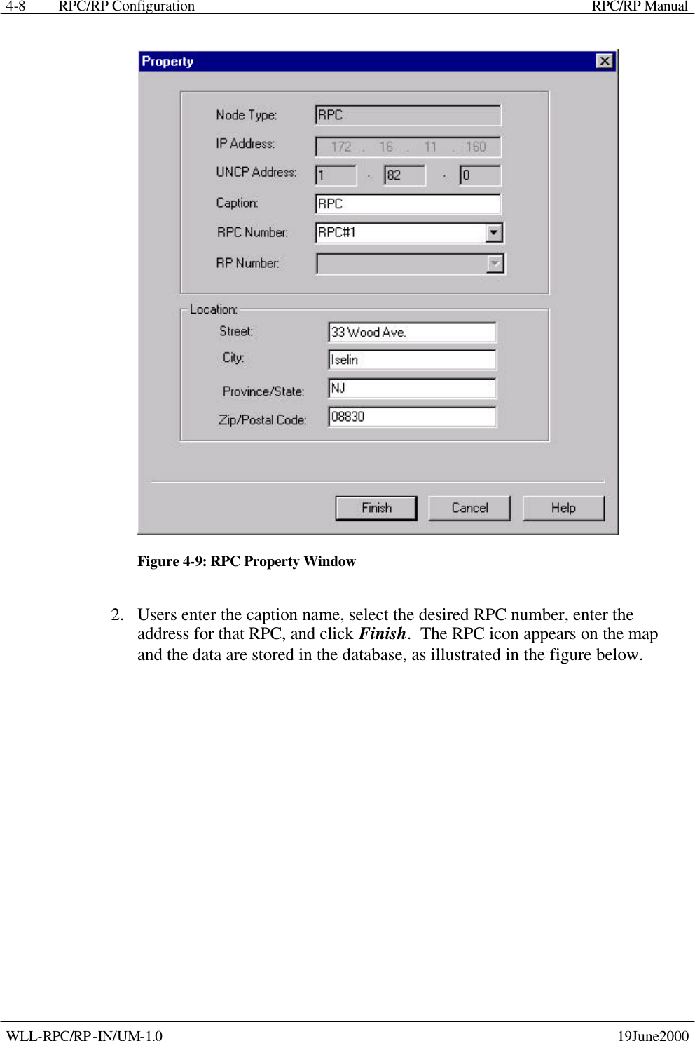
- 3. Users manual statement
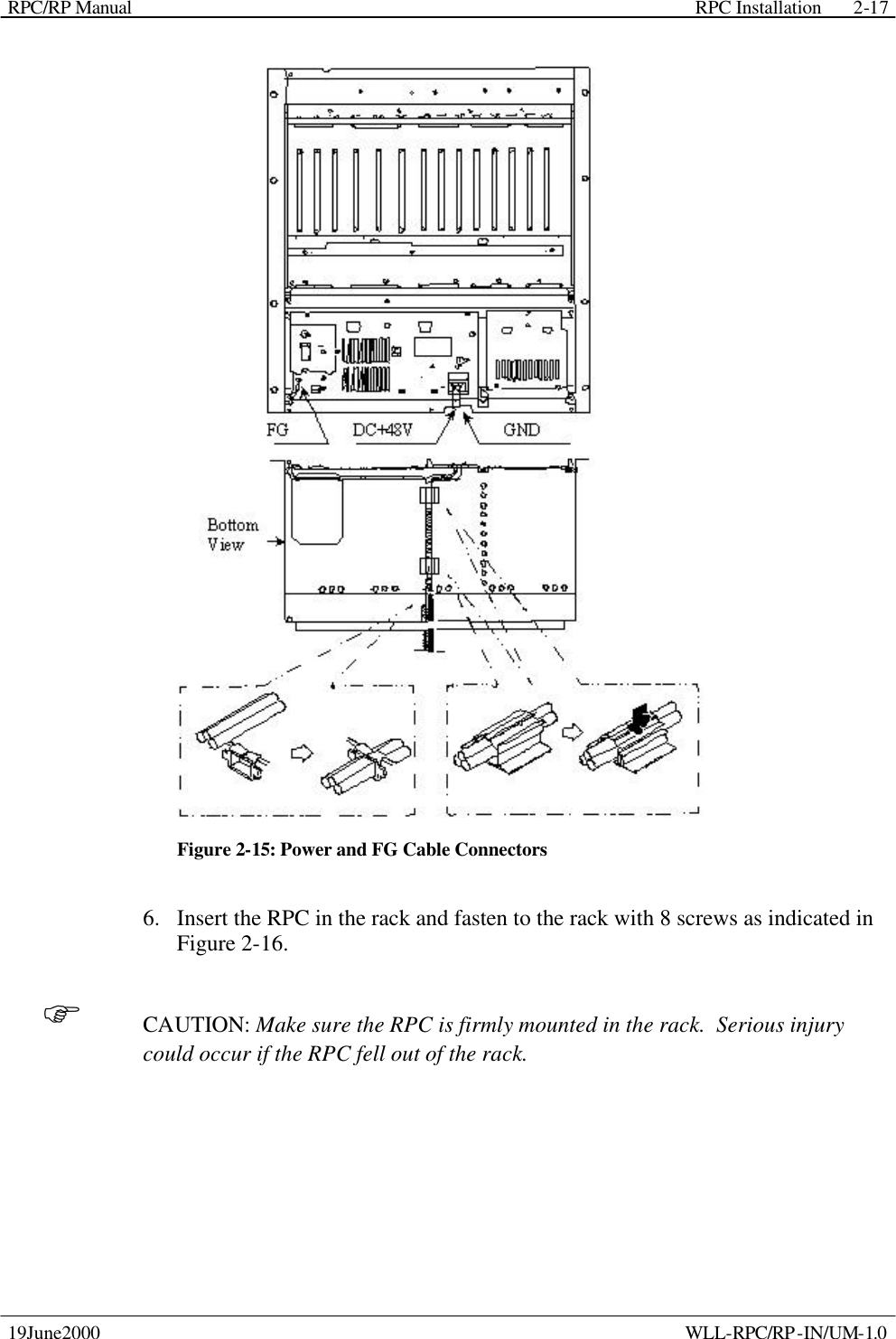
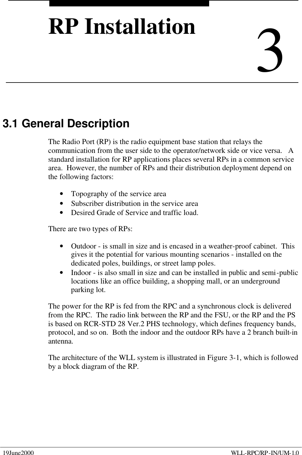
Users Manual 1 to 75