UTStarcom Korea Technologies UTS-EA7H74B Indoor PCS Band Pico Base Station User Manual Cover
UTStarcom Korea Technologies Ltd. Indoor PCS Band Pico Base Station Cover
UserManual.wiki
>
UTStarcom Korea Technologies
>
UTS-EA7H74B User Manual
>
Manual Part 2
Contents
1.
Manual Part 2
2.
Manual Part 1
3.
Manual statement
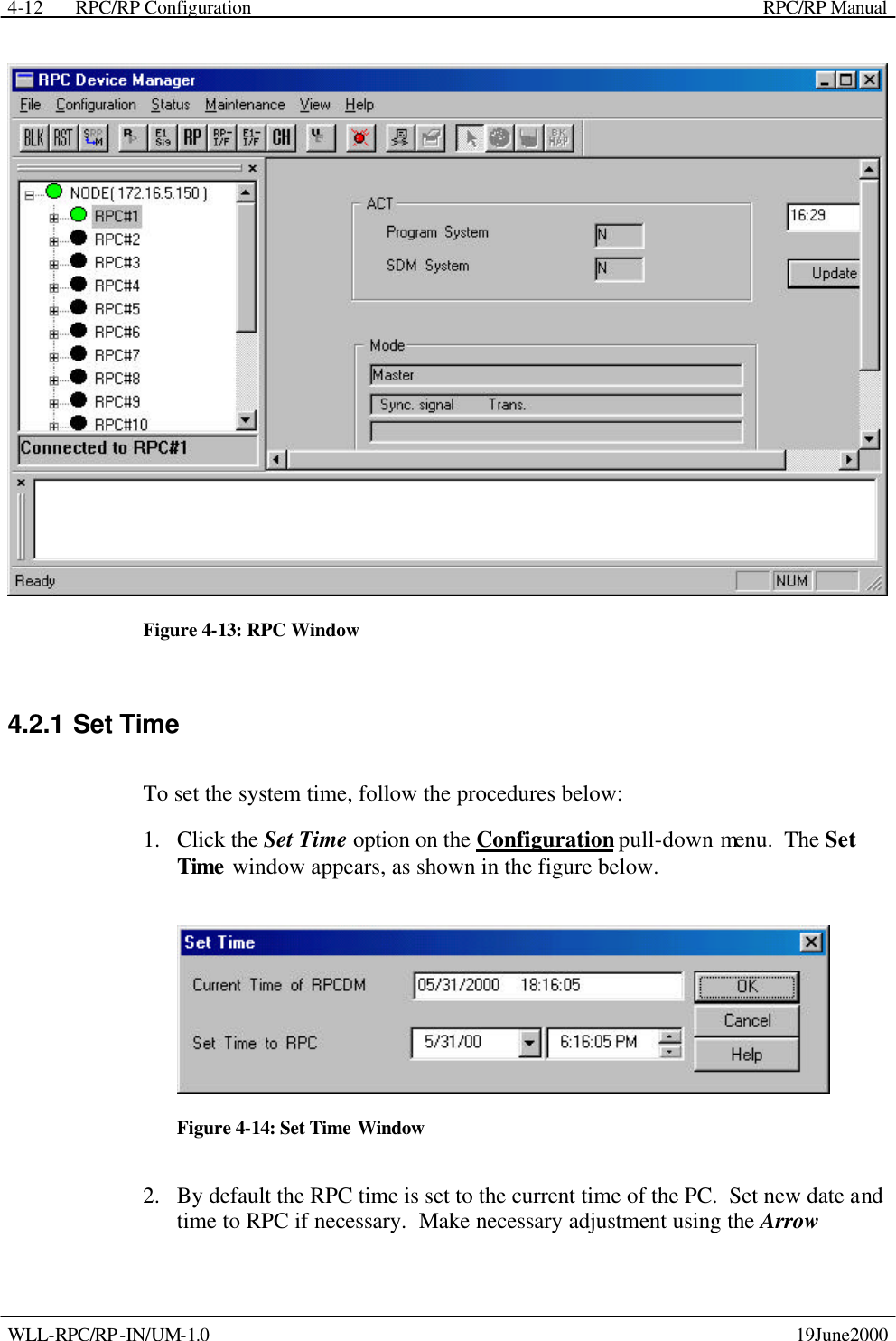
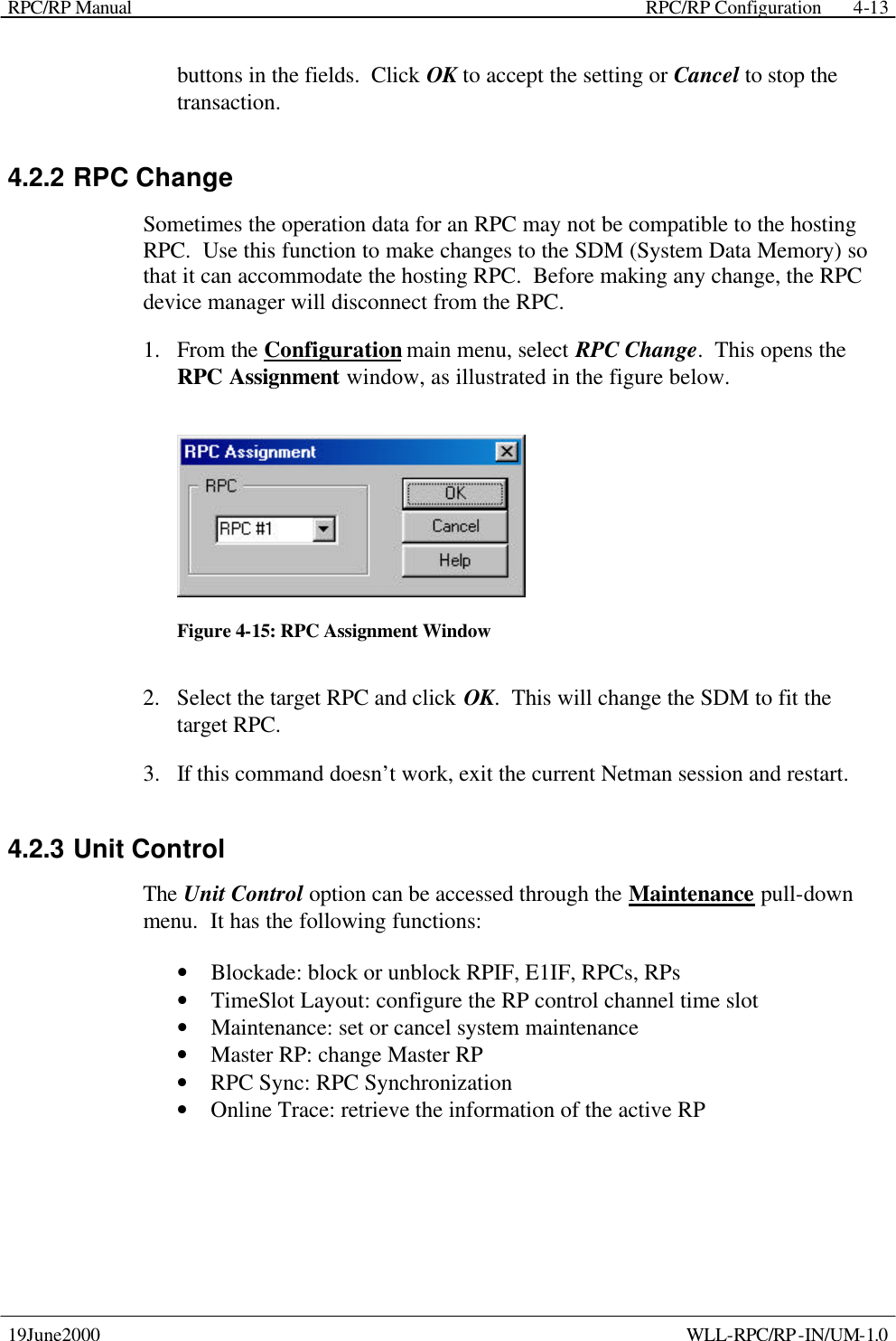
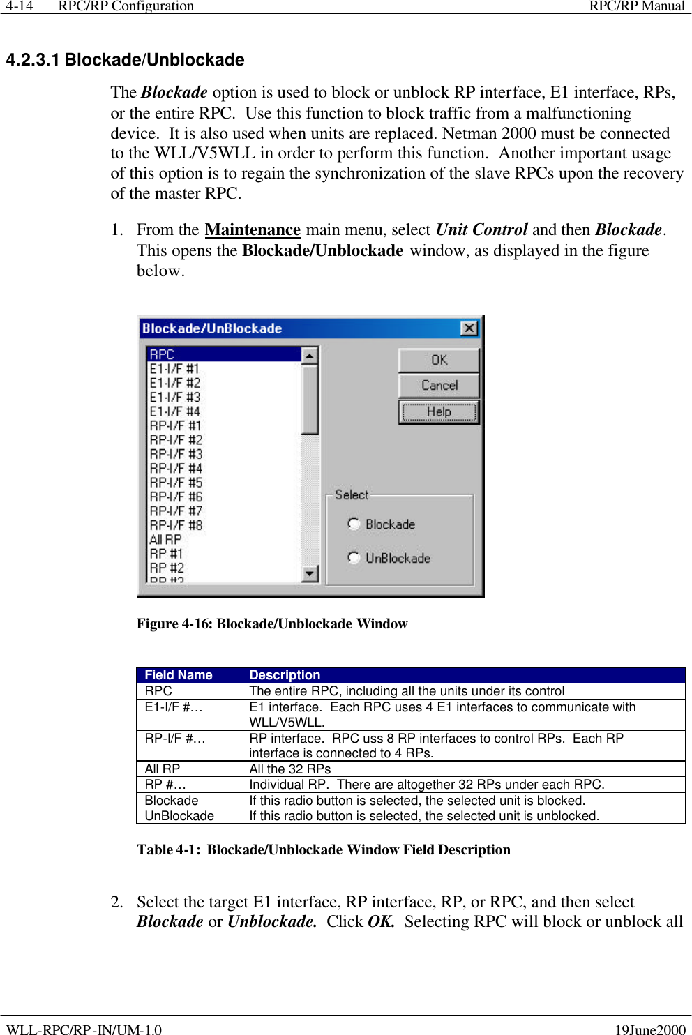
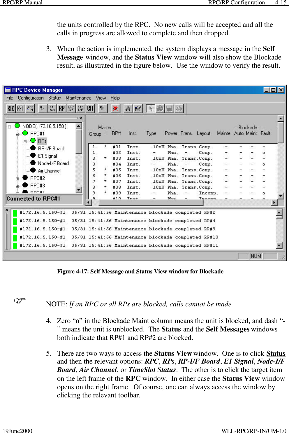
Manual Part 2
Navigation menu
Upload a User Manual
Namespaces
Wiki Guide
HTML
PDF
Info
Views
User Manual
Discussion / Help
Navigation