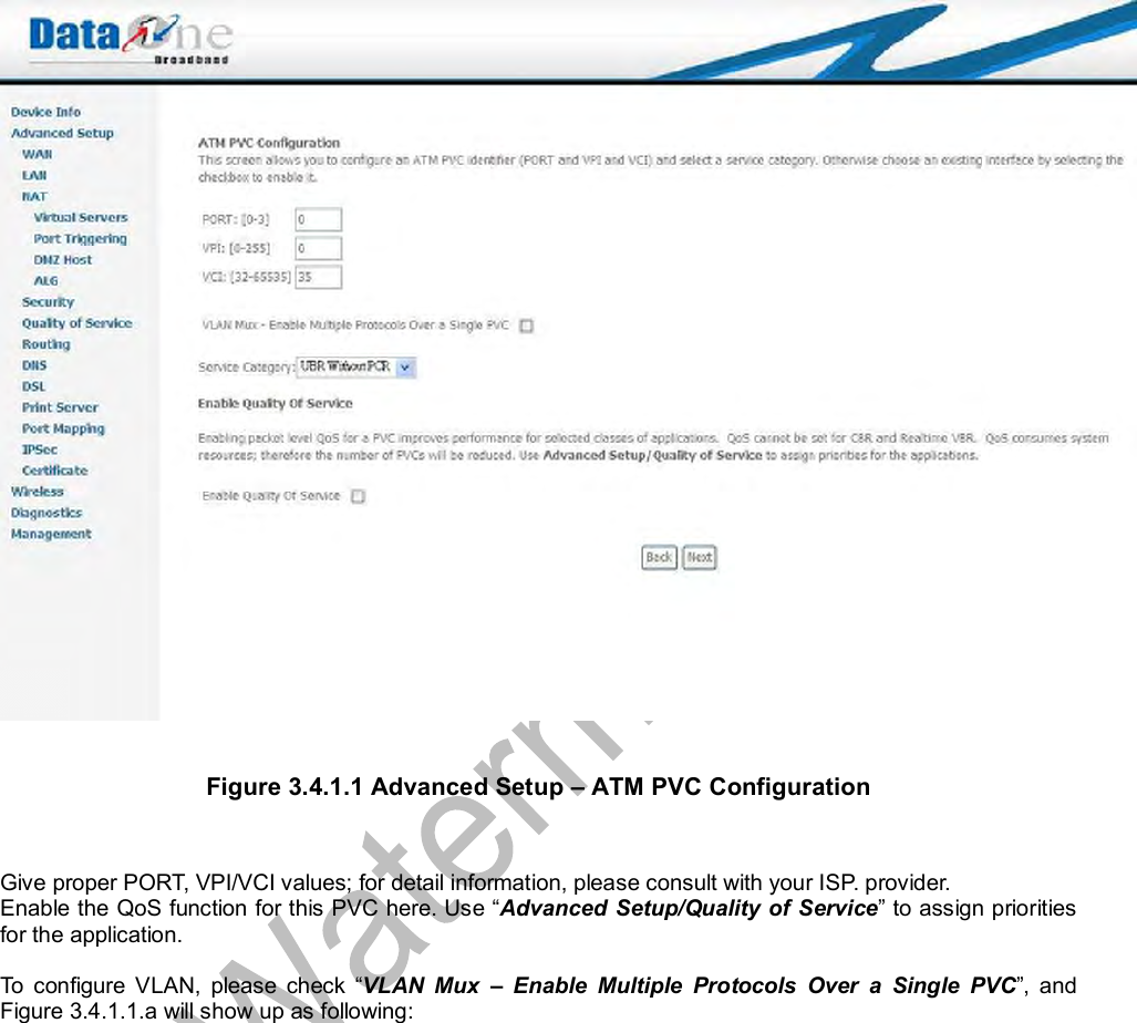
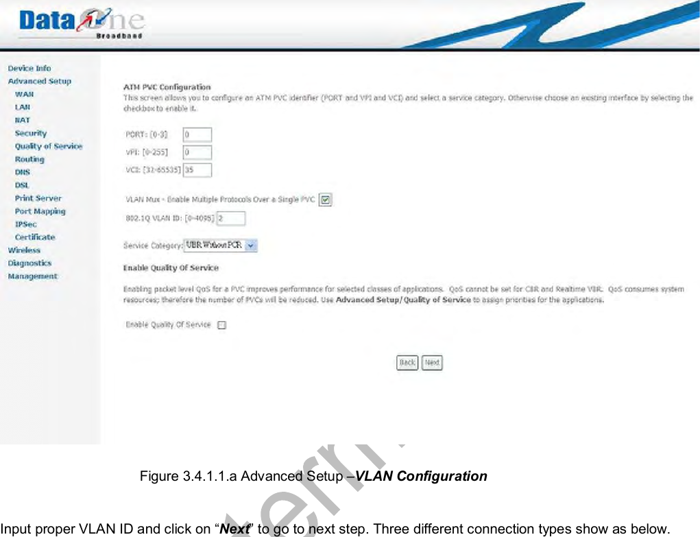
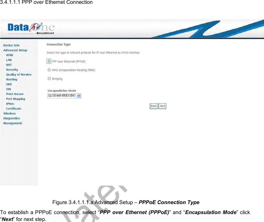
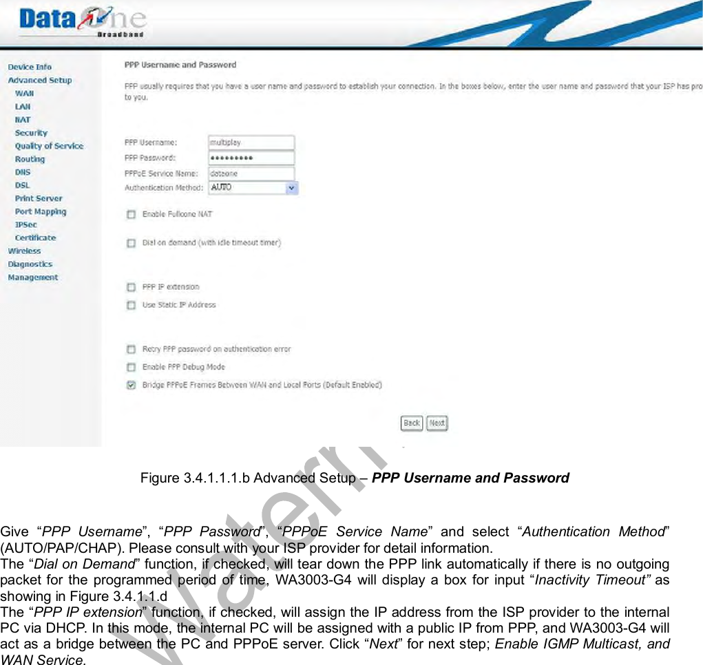
UTStarcom Korea Technologies WA3003G4 VDSL2 AP User Manual WA3003 G4
UTStarcom Korea Technologies Ltd. VDSL2 AP WA3003 G4
UserManual.wiki
>
UTStarcom Korea Technologies
>
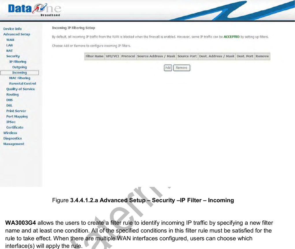
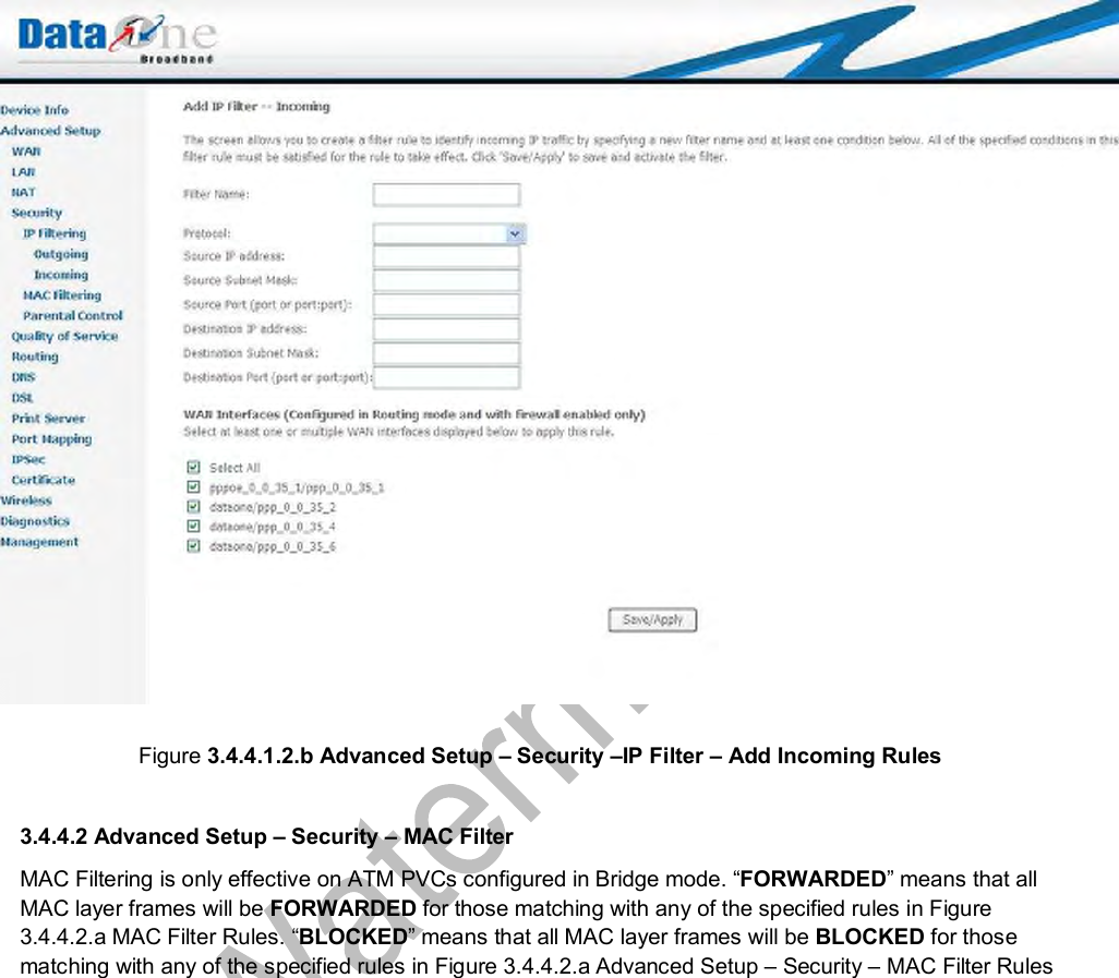
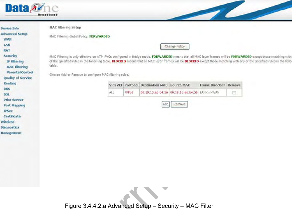
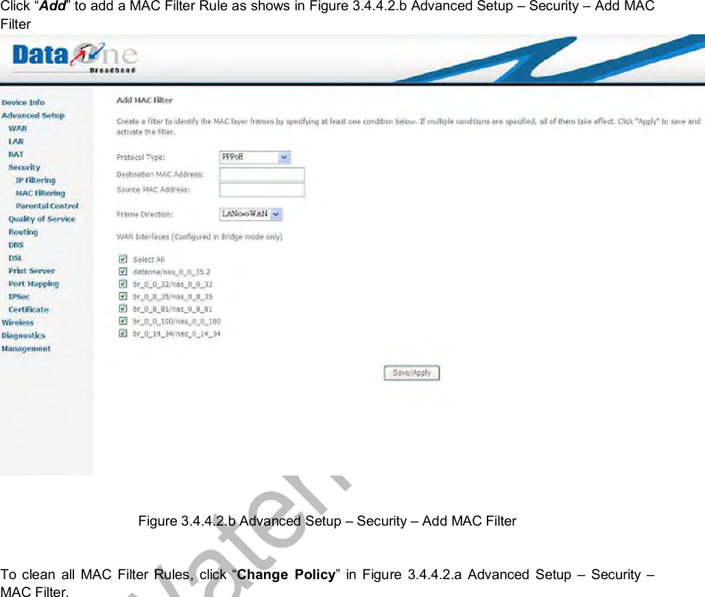
WA3003G4 User Manual
Manual
Navigation menu
Upload a User Manual
Namespaces
Wiki Guide
HTML
PDF
Info
Views
User Manual
Discussion / Help
Navigation