UTStarcom MSG2000 Multi-Service Gateway User Manual
UTStarcom Inc. Multi-Service Gateway Users Manual
Users Manual

FlexPacket ATCA PP50 Packet Processor
User Manual
CC06786-11B
Continuous Computing, the Continuous Computing logo, Create | Deploy | Converge, Flex21,
FlexChassis, FlexCompute, FlexCore, FlexDSP, FlexPacket, FlexStore, FlexSwitch, Network Service-
Ready Platform, Quick!Start, TAPA, Trillium, Trillium+plus, Trillium Digital Systems, Trillium On Board,
TAPA, and the Trillium logo are trademarks or registered trademarks of Continuous Computing
Corporation. Other names and brands may be claimed as the property of others.
This document is confidential and proprietary to Continuous Computing Corporation. No part of this
document may be reproduced, stored, or transmitted in any form by any means without the prior written
permission of Continuous Computing Corporation.
Information furnished herein by Continuous Computing Corporation, is believed to be accurate and
reliable. However, Continuous Computing Corporation assumes no liability for errors that may appear in
this document, or for liability otherwise arising from the application or use of any such information or for
any infringement of patents or other intellectual property rights owned by third parties, which may result
from such application or use. The products, their specifications, and the information appearing in this
document are subject to change without notice.
The information contained in this document is provided “as is” without any express representations on
warranties. In addition, Continuous Computing Corporation disclaims all statutory or implied
representations and warranties, including, without limitations, any warranty of merchantability, fitness for a
particular purpose, or non-infringement of third-party intellectual property rights.
To the extent this document contains information related to software products you have not licensed from
Continuous Computing Corporation, you may only apply or use such information to evaluate the future
licensing of those products from Continuous Computing Corporation. You should determine whether or not
the information contained herein relates to products licensed by you from Continuous Computing
Corporation prior to any application or use.
Contributors: Continuous Computing Development Team, Naveen D’cruz, Kevin MacDowell.
Printed in U.S.A.
Copyright 2011 by Continuous Computing Corporation. All rights reserved.
Preliminary
This device complies with Part 15 of the FCC Rules. Operation is subject to the following two
conditions: (1) this device may not cause harmful interference, and (2) this device must accept
any interference received, including interference that may cause undesired operation.
The user manual or instruction manual for an intentional or unintentional radiator shall caution
the user that changes or modifications not expressly approved by the party responsible for
compliance could void the user's authority to operate the equipment. In cases where the manual is
provided only in a form other than paper, such as on a computer disk or over the Internet, the
information required by this section may be included in the manual in that alternative form,
provided the user can reasonably be expected to have the capability to access information in that
form.
NOTE: This equipment has been tested and found to comply with the limits for a Class B digital
device, pursuant to Part 15 of the FCC Rules. These limits are designed to provide reasonable
protection against harmful interference in a residential installation. This equipment generates,
uses and can radiate radio frequency energy and, if not installed and used in accordance with the
instructions, may cause harmful interference to radio communications. However, there is no
guarantee that interference will not occur in a particular installation. If this equipment does cause
harmful interference to radio or television reception, which can be determined by turning the
equipment off and on, the user is encouraged to try to correct the interference by one or more of
the following measures:
-- Reorient or relocate the receiving antenna.
-- Increase the separation between the equipment and receiver.
-- Connect the equipment into an outlet on a circuit different from that to which the receiver is
connected.
-- Consult the dealer or an experienced radio/TV technician for help.

Page 5
CC06786-11B
Confidential and Proprietary
Preliminary
Contents
1 Introduction 19
1.1 Part Numbers and Options.......................................................................... 20
1.1.1 Part Numbers ................................................................................ 20
1.1.2 Basic Configurations ..................................................................... 21
1.1.3 RTM ............................................................................................... 21
1.1.4 Accessories ................................................................................... 21
1.2 Glossary ...................................................................................................... 22
1.3 Additional Documentation ........................................................................... 25
2 Technical Overview 27
2.1 Main Features ............................................................................................. 28
2.1.1 RMI Processor Subsystem ............................................................ 28
2.1.2 Ethernet Switch Module ................................................................ 28
2.1.3 RTM Interface ................................................................................ 28
2.2 Hardware Overview..................................................................................... 29
2.2.1 Front Panel Ports .......................................................................... 29
2.2.2 Backplane Interface ....................................................................... 29
2.2.3 Connectors .................................................................................... 30
2.2.3.1 Internal Connectors ....................................................... 30
2.2.3.2 External Connectors ..................................................... 30
2.2.3.3 ATCA Connectors ......................................................... 30
2.2.4 Graphical Overview ....................................................................... 31
2.2.5 RMI Processor CPU Subsystem ................................................... 33
2.2.5.1 PSRAM (Flight Recorder Memory) ............................... 34
2.2.6 Fabric and Base Switch Modules .................................................. 36
2.2.7 Optional TCAM Mezzanine ........................................................... 38
2.2.8 RTM interface ................................................................................ 38
Page 6
User Manual
Continuous Computing Corporation
FlexPacket ATCA PP50 Packet Processor
Preliminary
2.2.9 Management Subsystem ............................................................... 40
2.2.10 Front Panel .................................................................................... 40
2.2.10.1 LEDs ............................................................................. 40
2.2.10.2 Handle Switch ............................................................... 42
2.2.10.3 Management Port ......................................................... 42
2.2.10.4 Console Port ................................................................. 42
2.2.10.5 10GBASE-X Port .......................................................... 42
2.2.11 Jumpers ......................................................................................... 43
2.2.11.1 Default Jumper Settings ............................................... 43
2.2.11.2 Force Power On Jumper: J116 ..................................... 44
2.2.11.3 Console Mux Bypass Jumpers: J112, J113 .................. 45
2.2.11.4 Spare Serial Config Jumper: J111 ................................ 45
2.2.11.5 Alt Boot Bank Select Jumpers: J117, J118 ................... 45
2.2.11.6 Reserved Jumpers ........................................................ 46
2.2.12 Power Design ................................................................................ 46
2.2.13 Mean Time Between Failures ........................................................ 46
2.3 Component Integration Overview................................................................ 47
2.3.1 Firmware ....................................................................................... 47
2.3.2 IPMI ............................................................................................... 48
2.3.3 IPMC ............................................................................................. 48
2.3.4 IPMC and XLR Software Domains ................................................ 49
2.3.5 XLR Watchdog Timers .................................................................. 49
2.3.6 XLR Software ................................................................................ 49
2.3.7 XLR and IPMC Messaging ............................................................ 51
2.3.8 Power Domains ............................................................................. 53
2.4 Specifications .............................................................................................. 55
2.4.1 CPU / Memory ............................................................................... 55
2.4.2 Input/Output ................................................................................... 55
2.4.3 Expansion Options ........................................................................ 55
2.4.4 Software ........................................................................................ 55
2.4.5 Mechanical & Environmental Compliance ..................................... 55
2.4.6 Fuses ............................................................................................. 56
2.4.7 Certifications .................................................................................. 56
2.4.7.1 Planned Certifications ................................................... 56
2.4.8 Power Consumption ...................................................................... 56
3 Board Installation 57
3.1 Precautions ................................................................................................. 58
3.1.1 Environmental Requirements ........................................................ 58
3.1.2 Heat Dissipation and Dust Prevention ........................................... 58
3.1.3 Electrostatic Prevention ................................................................. 58
3.1.4 Other Precautions ......................................................................... 59
3.2 Unpacking the PP50 ................................................................................... 60
3.2.1 Compact Flash .............................................................................. 60
Page 7
CC06786-11B
Confidential and Proprietary
Contents
1
4ABAB
Preliminary
3.2.2 Board Identification ........................................................................ 61
3.2.2.1 Serial Number ............................................................... 61
3.2.2.2 MAC Address ................................................................ 62
3.2.2.3 Part Number ................................................................. 63
3.2.2.4 MAC Address Location ................................................. 63
3.2.2.5 IPMI Manufacturing Info ................................................ 63
3.3 Installing PP50s into the Chassis................................................................ 64
3.3.1 Where to Install the PP50 .............................................................. 64
3.3.2 Board Insertion .............................................................................. 65
3.3.3 Air Blocker Modules in Vacant Slots ............................................. 69
4 Board Access, Bootup, and Shutdown 71
4.1 Serial Console Access ................................................................................ 72
4.1.1 Connect to the Serial Console ....................................................... 72
4.1.2 How to Switch Between Serial Consoles (IPMC, XLRs) ............... 73
4.2 IPMC Telnet Access.................................................................................... 75
4.2.1 Setting eth0 IP Address Manually ................................................. 75
4.2.2 Setting eth0.4094 IP Address Manually ........................................ 75
4.2.3 Setting the DNS Manually ............................................................. 76
4.3 Console Access for Development ............................................................... 77
4.3.1 Development Adapter (Hydra) Cable ............................................ 77
4.4 Board Shutdown.......................................................................................... 79
4.4.1 Using the IPMI Command to Shutdown ........................................ 79
4.4.2 Using the Handle Latch to Shutdown ............................................ 79
4.5 Board Reset ................................................................................................ 80
4.5.1 IPMI Cold Reset Command ........................................................... 80
4.5.2 IPMC (CNode) Reboot .................................................................. 80
5 Using the XLR SDK 81
5.1 Installing RMI Source Code & Development Tools ..................................... 82
5.2 Installing Continuous Computing Software ................................................. 83
5.3 Build the Linux Kernel ................................................................................. 84
5.3.1 Apply Kernel Patches to the RMI SDK Kernel Source .................. 84
5.3.1.1 Example of Using the Patch ......................................... 84
5.3.2 Build the Patched Linux Kernel ..................................................... 84
5.4 Cross Compiling Linux Applications using the RMI SDK Crosscompiler .... 86
6 Booting the XLRs 87
6.1 XLR Boot Methods ...................................................................................... 88
6.1.1 Network Boot ................................................................................. 88
6.1.1.1 Boot Server setup ......................................................... 88
6.1.1.2 PP50 Setup ................................................................... 88
6.1.1.3 Network Boot Example ................................................. 89
6.1.2 XLR Bootloader Commands .......................................................... 90
Page 8
User Manual
Continuous Computing Corporation
FlexPacket ATCA PP50 Packet Processor
Preliminary
6.1.3 Compact Flash Boot ...................................................................... 91
6.1.3.1 Formatting Compact Flash ........................................... 92
6.1.3.2 Booting from Compact Flash ........................................ 92
6.2 Automating XLR boot .................................................................................. 94
6.2.1 Continuous Computing Multiboot .................................................. 94
6.2.1.1 Key Values (KV) ........................................................... 94
6.2.1.2 KV Variable Syntax ....................................................... 95
6.2.1.3 Access to Multiple Boot Method ................................... 96
6.2.1.4 Boot Method Syntax ..................................................... 96
6.2.1.5 Specifying Boot file ....................................................... 97
6.2.1.6 Specifying Boot command ............................................ 97
6.2.1.7 Specifying Boot Arguments .......................................... 98
6.2.1.8 Watchdog Feature ........................................................ 98
6.2.1.9 Initializing Multiboot ...................................................... 99
6.2.1.10 Multiboot Example ...................................................... 101
6.2.2 Autobooting Using Environment Variables .................................. 101
6.3 XLR Utility ................................................................................................. 102
6.3.1 Installing Linux Utilities ................................................................ 102
6.3.1.1 RMI Linux .................................................................... 102
6.3.1.2 WR Linux .................................................................... 102
6.3.2 XLR Commands Available From the BootLoader ....................... 103
6.3.2.1 kv ................................................................................ 103
6.3.2.2 showboot .................................................................... 104
6.3.2.3 rollboot ........................................................................ 104
6.3.3 XLR Commands Available From Linux ....................................... 104
6.3.3.1 NTP client ................................................................... 104
6.3.3.2 kv ................................................................................ 104
6.3.3.3 showboot .................................................................... 104
6.3.3.4 rollboot ........................................................................ 105
6.3.3.5 ipmi_setwd .................................................................. 105
6.3.3.6 fswcmd ........................................................................ 105
6.3.3.7 upgrade ....................................................................... 106
6.3.3.8 bswcmd ....................................................................... 106
6.3.3.9 getcpuid ...................................................................... 106
6.3.3.10 net_config ................................................................... 107
6.3.3.11 ipmi_setwd .................................................................. 107
6.3.3.12 ux_diag ....................................................................... 108
7 Intelligent Platform Management Controller 109
7.1 FRU Support ............................................................................................. 110
7.1.1 FRU State .................................................................................... 110
7.1.2 FRU Hot swap Sensors ............................................................... 111
7.1.3 FRU Data .................................................................................... 111
7.1.3.1 Example of FRU Data using Pigeon Point ShMc ........ 111
7.2 Sensors ..................................................................................................... 114
7.3 Link Descriptors ........................................................................................ 118
Page 9
CC06786-11B
Confidential and Proprietary
Contents
1
4ABAB
Preliminary
7.3.1 PP50 with 10G Fabric Link Descriptors (shelf manager) ............ 120
7.3.2 PP50 with 4*1G Fabric Link Descriptors (shelf manager) ........... 120
7.4 Key Value (KV) Database ......................................................................... 122
7.4.1 KV Keys ....................................................................................... 122
7.4.2 To List All Key Value Entries ....................................................... 132
7.5 IPMI and PICMG Commands.................................................................... 134
7.5.1 IPMI Device Global Commands .................................................. 135
7.5.2 BMC Watchdog Timer Commands .............................................. 135
7.5.3 Chassis Device Commands ........................................................ 135
7.5.4 Event Commands ........................................................................ 136
7.5.5 Sensor Device Commands .......................................................... 136
7.5.6 FRU Device Commands .............................................................. 138
7.5.7 SDR Device Commands ............................................................. 138
7.5.8 SEL Device Commands .............................................................. 138
7.5.9 ATCA (PICMG 3.0) Commands .................................................. 139
7.5.9.1 FRU Control Command .............................................. 140
7.5.10 OEM API Commands .................................................................. 141
7.5.10.1 Get Payload CPU-Reset ............................................. 141
7.5.10.2 Set Payload CPU-Reset ............................................. 143
7.5.10.3 Get Payload Active Flash Bank .................................. 143
7.5.10.4 Set Payload Active Flash Bank ................................... 144
7.5.10.5 Get Self Payload ID .................................................... 145
7.5.10.6 Get Payload ID for Watchdog Commands .................. 146
7.5.10.7 Set Payload ID for Watchdog Commands .................. 148
7.5.10.8 Get IPMC Key N ......................................................... 149
7.5.10.9 Get IPMC Key-Value .................................................. 150
7.5.10.10 Set IPMC Key-Value ................................................... 151
7.5.10.11 Get IPMC Key-Value Extended .................................. 153
7.5.10.12 Set IPMC Key-Value Extended ................................... 154
7.5.10.13 Sensor Thresholds and Hysteresis Overview ............. 155
7.5.11 IPMI Command Completion Codes ............................................. 158
7.6 Error Logging ............................................................................................ 160
7.7 Behavior of IPMI Resets ........................................................................... 161
7.7.1 IPMI Cold Reset .......................................................................... 161
7.7.2 IPMI Watchdog Reset ................................................................. 161
7.7.2.1 Linux Application Level ............................................... 161
7.7.2.2 Hardware Level ........................................................... 161
7.7.3 IPMI Firmware Upgrade Reset .................................................... 162
7.8 IPMC Command Line Interface................................................................. 163
7.8.1 bmc_watchdog ............................................................................ 164
7.8.2 commit ......................................................................................... 164
7.8.3 debuglevel ................................................................................... 165
7.8.4 getactivebank .............................................................................. 165
7.8.5 getresetstatus .............................................................................. 166
7.8.6 help .............................................................................................. 166
7.8.7 kv ................................................................................................. 167
Page 10
User Manual
Continuous Computing Corporation
FlexPacket ATCA PP50 Packet Processor
Preliminary
7.8.8 listdev .......................................................................................... 168
7.8.9 listfwdev ....................................................................................... 168
7.8.10 listpay .......................................................................................... 168
7.8.11 localaddress ................................................................................ 169
7.8.12 quit ............................................................................................... 169
7.8.13 resetdev ....................................................................................... 169
7.8.14 restore ......................................................................................... 169
7.8.15 sel ................................................................................................ 170
7.8.16 sendcmd ...................................................................................... 170
7.8.17 setactivebank .............................................................................. 171
7.8.18 setresetstatus .............................................................................. 171
7.8.19 version ......................................................................................... 171
8 Network Configuration 173
8.1 Fabric Switch Models ................................................................................ 175
8.2 Fabric Switch Management....................................................................... 176
8.2.1 Managing the Fabric Switch with fswcmd ................................... 176
8.2.1.1 autopause ................................................................... 177
8.2.1.2 reload .......................................................................... 177
8.2.1.3 show stats ................................................................... 178
8.2.1.4 clear ............................................................................ 178
8.2.1.5 route ............................................................................ 178
8.2.1.6 set port ........................................................................ 178
8.2.1.7 enable/disable port ..................................................... 179
8.2.1.8 enable/disable port e-keying ....................................... 179
8.2.1.9 enable/disable ingress vlan ........................................ 180
8.2.1.10 enable/disable accept untagged port .......................... 180
8.2.1.11 set port default ............................................................ 180
8.2.1.12 add vlan ...................................................................... 180
8.2.1.13 del vlan ....................................................................... 181
8.2.1.14 show ........................................................................... 181
8.2.1.15 SFP Commands ......................................................... 181
8.2.1.16 show Commands ........................................................ 181
8.2.1.17 cfgreg .......................................................................... 182
8.2.1.18 dump ........................................................................... 182
8.2.1.19 show version ............................................................... 182
8.2.1.20 dump ........................................................................... 182
8.2.1.21 enable | disable mac-learning ..................................... 182
8.2.1.22 enable | disable flooding broadcast ............................ 182
8.2.1.23 high and low watermark range .................................... 183
8.2.1.24 enable | disable protocol-traps .................................... 183
8.2.1.25 show link ..................................................................... 183
8.2.1.26 MAC aging .................................................................. 184
8.2.2 fswcmd Start Up File ................................................................... 184
8.2.3 FIBM Mode .................................................................................. 185
8.2.3.1 Enabling FIBM Mode .................................................. 186
Page 11
CC06786-11B
Confidential and Proprietary
Contents
1
4ABAB
Preliminary
8.3 Base Switch Management and Port Connectivity ..................................... 187
8.3.1 Default Behavior .......................................................................... 187
8.3.1.1 Broadcom Management Tag (BMT) ........................... 188
8.3.1.2 Register Initialization in u-boot .................................... 189
8.3.2 Configurable Behavior ................................................................. 191
8.3.3 Alternate bswitch Behavior .......................................................... 194
8.3.4 Configuration ............................................................................... 194
8.3.4.1 num_of_fakes: .......................................................... 194
8.3.4.2 vlan_method .............................................................. 194
8.3.5 Design Overview ......................................................................... 195
8.3.5.1 VLAN mode ............................................................... 196
8.3.5.2 BMT Mode ................................................................. 196
8.3.6 Key Value Database Syntax ........................................................ 197
8.3.7 Examples ..................................................................................... 197
8.3.7.1 VLAN method ............................................................ 197
8.3.7.2 Mask Method ............................................................ 198
8.3.8 Front Mode .................................................................................. 198
8.3.9 RTM Mode ................................................................................... 198
8.4 Ethernet Ports on the RTM ....................................................................... 199
8.5 Fabric and Base Switch Management....................................................... 199
8.6 CNode Base Switch (bswcmd) Command ................................................ 200
8.6.1 Binding bswcmd to the CNODE's IP ........................................... 200
8.6.2 bswcmd Usage Examples ........................................................... 200
8.6.2.1 Common bswcmd Commands .................................... 200
8.6.3 Fabric Switch ............................................................................... 202
8.7 Configuring XLR Network Interfaces using KV.......................................... 203
8.7.1 Configuring XLR Network Interfaces Example ............................ 204
9 Using Wind River Linux on the PP50 205
9.1 Overview ................................................................................................... 206
9.1.1 CCPU/WindRiver Release Compatibility ..................................... 206
9.1.2 Installation Requirements ............................................................ 207
9.1.2.1 For WindRiver PNE LE 2.0 ......................................... 207
9.2 Installing the Template and Patch............................................................. 208
9.2.1 Installation Steps for WindRiver PNE 2.0 .................................... 208
9.3 Building the Kernel and NFS..................................................................... 209
9.3.1 Installing the Boot Kernel and NFS ............................................. 217
9.3.2 Booting the Target Blade ............................................................. 217
9.4 Memory Map Setup................................................................................... 218
9.5 Linux Setup ............................................................................................... 218
9.6 Linux Command Line Options................................................................... 219
9.6.1 linux_cpu_mask=<cpu_mask> .................................................... 219
9.6.2 kseg0_start=<address> ............................................................... 219
9.6.3 kseg0_size=<size> ...................................................................... 219
9.6.4 kumem=<size@addr> ................................................................. 220
9.6.4.1 Examples of Using kumen .......................................... 220
Page 12
User Manual
Continuous Computing Corporation
FlexPacket ATCA PP50 Packet Processor
Preliminary
9.6.5 kuseg_start_hi=<hi_address> ..................................................... 221
9.6.6 kuseg_start_lo=<lo_address> ..................................................... 221
9.6.7 kuseg_size_hi=<hi_size> ............................................................ 221
9.6.8 kuseg_size_lo=<lo_size> ............................................................ 221
9.6.9 app_sh_mem_sz=<hex_size> .................................................... 222
9.6.10 shared_core ................................................................................ 222
9.7 Linux Loader Applications ......................................................................... 223
9.7.1 userapp ....................................................................................... 223
9.7.1.1 load ............................................................................. 223
9.7.1.2 stop ............................................................................. 224
9.7.1.3 status .......................................................................... 224
9.7.1.4 showmem ................................................................... 224
9.7.1.5 shmem ........................................................................ 225
9.8 Building an RMIOS application ................................................................. 226
9.8.1 Building KSEG0 applications ....................................................... 226
9.8.2 Stop and Re-load support ........................................................... 226
10 Rear Transition Modules 227
10.1 Standard RTM........................................................................................... 228
10.1.1 Standard RTM Features .............................................................. 228
10.1.2 Specifications and Features ........................................................ 228
10.1.2.1 General ....................................................................... 228
10.1.2.2 Mechanical .................................................................. 228
10.1.2.3 Power .......................................................................... 229
10.1.2.4 Management .............................................................. 229
10.2 COP50 RTM.............................................................................................. 230
10.2.1 COP50 Features ......................................................................... 230
10.2.2 Important COP50 Terms Definitions ........................................... 231
10.2.3 COP50 RTM Overview ................................................................ 232
10.2.3.1 Bypass protection ....................................................... 234
10.2.4 COP50 Specifications and Features ........................................... 234
10.2.4.1 General ....................................................................... 234
10.2.4.2 Mechanical .................................................................. 234
10.2.4.3 Power .......................................................................... 234
10.2.4.4 Management .............................................................. 235
10.2.4.5 Bypass protection ...................................................... 236
10.2.4.6 IPMC Firmware .......................................................... 236
10.2.5 Installation and Usage ................................................................. 236
10.2.5.1 Initial Installation ......................................................... 236
10.2.5.2 PP50 IPMC Bootup and the COP50 ........................... 237
10.2.5.3 RTM Insertion ............................................................. 238
10.2.5.4 Upgrading the COP50 RTM CPLD ............................. 238
10.2.5.5 RTM Removal ............................................................. 239
10.2.5.6 Auto-Arm versus Managed Re-Arming ....................... 239
10.2.5.7 Software Specifications .............................................. 239
10.2.5.8 COP50 Usage Example .............................................. 243

Page 2-13
CC06786-11B
Confidential and Proprietary
Contents
1
4ABAB
Preliminary
11 Firmware Upgrades 245
11.1 CPLD Upgrade.......................................................................................... 245
11.1.1 CPLD Upgrade Examples ........................................................... 246
11.2 XLR bootloader Upgrade .......................................................................... 247
11.2.1 Get Image File ............................................................................. 247
11.2.1.1 Upgrade Boot Flash Via Network ............................... 247
11.2.1.2 Get Bootloader Image File from TFTP Server ............ 247
11.2.2 Loading Image Files .................................................................... 247
11.2.2.1 Ping-Pong Upgrade Method ....................................... 248
11.2.2.2 Factory Golden Upgrade Method ............................... 249
11.3 Upgrading the PP50 IPMC........................................................................ 252
11.3.1 Upgrading Versions 2.3.x or Later to a Higher Version ............... 252
11.3.2 Upgrading Versions 2.2.x or Earlier to a Higher Version ............. 253
11.3.3 Showing, Switching, and Rebooting Boot Banks ........................ 255
11.4 Linux Bootloader Upgrade Tool ................................................................ 257
11.4.1 In WR Linux ................................................................................. 257
11.4.2 In RMI Linux ................................................................................ 258
11.5 XLR Fabric Switch Configuration Utility, Installation ................................. 259
12 Diagnostics and Troubleshooting 261
12.1 Overview ................................................................................................... 261
12.2 Running Diagnostic Tests from Raw CLI .................................................. 262
12.2.1 IPMC Raw CLI Diagnostic Commands ....................................... 262
12.2.2 XLR Raw CLI Diagnostic Commands ......................................... 263
12.3 Running Diagnostic Tests using KV Settings............................................ 265
12.3.1 Running IPMC Diagnostic tests with KV settings ........................ 266
12.3.1.1 IPMC U-boot command for short/long POST tests ..... 266
12.3.1.2 IPMC Linux utility for POST/BIST tests ...................... 267
12.3.2 Running XLR Diagnostic Tests with KV settings ......................... 269
12.3.2.1 XLR Commands for Short/Long POST tests .............. 269
12.3.2.2 XLR RMI Linux Utility for POST/BIST Tests ............... 271
12.4 Indicating XLR’s POST/BIST Status Using LEDs ..................................... 275
12.5 Determining Board Build ........................................................................... 276
13 Product Repair and Returns 277
13.1 Customer Support ..................................................................................... 277
13.2 Warranty.................................................................................................... 277
13.2.1 RMA Procedure ........................................................................... 278
13.2.2 Non-Warranty Repairs ................................................................. 278
13.2.3 Shipping ...................................................................................... 278
13.2.4 Expedite Option for Repairs ........................................................ 278
14 Revision History 279
Page 2-14
User Manual
Continuous Computing Corporation
FlexPacket ATCA PP50 Packet Processor
Preliminary

Page 15
CC06786-11B
Confidential and Proprietary
Preliminary
Figures
Figure 2-1 PP50 Overview Photo .................................................................................... 27
Figure 2-2 Front Panel ..................................................................................................... 29
Figure 2-3 Overall Hardware Block Diagram. .................................................................. 31
Figure 2-4 Base and Fabric Connection Diagram. ........................................................... 32
Figure 2-5 RMI Processor CPU Subsystem .................................................................... 33
Figure 2-6 Switch Module ................................................................................................ 36
Figure 2-7 RTM interface in Chassis ............................................................................... 38
Figure 2-8 RTM Panel ...................................................................................................... 39
Figure 2-9 Front Panel LEDs ........................................................................................... 40
Figure 2-10 IPMC Overview ............................................................................................. 48
Figure 2-11 XLR Software Overview ............................................................................... 49
Figure 2-12 XLR and IPMC Messaging ........................................................................... 51
Figure 2-13 XLR and IPMC Boot Messaging ................................................................... 51
Figure 2-14 XLR and IPMC Telnet Messaging ................................................................ 52
Figure 2-15 XLR and IPMC IPMI Messaging ................................................................... 52
Figure 2-16 Virtual Switches ............................................................................................ 53
Figure 2-17 Power Domains, Startup ............................................................................... 54
Figure 3-1 ESD Wrist Strap ............................................................................................. 59
Figure 3-2 PP50 Unpacking ............................................................................................. 60
Figure 3-3 Serial Number Location .................................................................................. 61
Figure 3-4 Part Number Location ..................................................................................... 63
Figure 3-5 MAC Address Location ................................................................................... 63
Figure 3-6 5U Chassis Slots ............................................................................................ 64
Figure 3-7 12U Chassis Slots .......................................................................................... 64
Figure 3-8 Latch Handle .................................................................................................. 65
Figure 3-9 Opening the Latch Handle, Lever Release ..................................................... 66
Figure 3-10 Opened Latch Handle ................................................................................... 66
Figure 3-11 Installation - Locator Pins ............................................................................. 67
Figure 3-12 Installation - Board Insertion ......................................................................... 68
Page 16
User Manual
Continuous Computing Corporation
FlexPacket ATCA PP50 Packet Processor
Preliminary
Figure 3-13 PP50 Installation - Board Insertion, Latch Closure ....................................... 69
Figure 4-1 Serial Console Cable ...................................................................................... 72
Figure 4-2 Connecting Computer to the Serial Console .................................................. 72
Figure 4-3 Hydra Cable for Multiple Simultaneous Connection ....................................... 77
Figure 4-4 Hydra Cable Jumpers (J111 and J113) .......................................................... 78
Figure 7-1 Get Payload Active Flash Bank Response Data .......................................... 144
Figure 7-2 Set Payload Active Flash Bank Request Data ............................................. 145
Figure 7-3 Set Payload Active Flash Bank Response Data .......................................... 145
Figure 8-1 Networking Components Diagram ............................................................... 174
Figure 8-2 Fulcrum In Band Management (FIBM) ......................................................... 185
Figure 8-3 PP50 Channel A and B Networks ................................................................ 188
Figure 8-4 Selective-mask bswitch Ingress Masks ........................................................ 190
Figure 8-5 BMT Mode eth0 egress ................................................................................ 191
Figure 8-6 BMT Mode eth1 egress ................................................................................ 192
Figure 8-7 BMT Mode eth1 ingress ............................................................................... 192
Figure 8-8 VLAN Mode eth0 egress .............................................................................. 193
Figure 8-9 VLAN Mode eth1 egress .............................................................................. 193
Figure 8-10 sysctl tree ................................................................................................... 195
Figure 9-1 WindRiver PNE LE 2.0 Files for CCPU Release 1.3 .................................... 207
Figure 9-2 Create a New Project ................................................................................... 209
Figure 9-3 Input the Name ............................................................................................. 210
Figure 9-4 Select Board ................................................................................................. 211
Figure 9-5 Static Analysis .............................................................................................. 212
Figure 9-6 Project Name ................................................................................................ 212
Figure 9-7 Linux Kernel Configuration ........................................................................... 213
Figure 9-8 Package Configuration ................................................................................. 214
Figure 9-9 Build WindRiver Linux Kernel ....................................................................... 215
Figure 9-10 Build WindRiver Linux NFS ........................................................................ 216
Figure 10-1 Standard RTM ............................................................................................ 228
Figure 10-2 COP50 RTM ............................................................................................... 230
Figure 10-3 COP50 Front View ..................................................................................... 232
Figure 10-4 RTM-COP50 Block Diagram ...................................................................... 233
Figure 10-5 cop50d daemon’s Internal State Model ...................................................... 240
Figure 11-1 Ping-Pong Upgrade Flow Diagram ............................................................. 249
Figure 11-2 Factory Golden Upgrade Flow Diagram ..................................................... 251
Figure 12-1 Diagnostic Tests Tree ................................................................................ 261

Page 17
CC06786-11B
Confidential and Proprietary
Preliminary
Tables
Table 1-1 PP50 and Accessory Part Numbers ........................................................ 20
Table 1-2 Terms Used in this Document.................................................................. 22
Table 2-1 RMI XLR Family Configurations............................................................... 33
Table 2-2 Ethernet Switch Operating Modes ........................................................... 37
Table 2-3 Ethernet Switch Port Usage..................................................................... 37
Table 2-4 LED Description....................................................................................... 41
Table 2-5 PP50 Jumper Information ........................................................................ 43
Table 2-6 Console Debug Bypass ........................................................................... 45
Table 2-7 Debug Mode – Triple MUX Modes........................................................... 45
Table 2-8 Reserved Jumpers................................................................................... 46
Table 2-9 PP50 Major Firmware Categories............................................................ 47
Table 2-10 Fuse Specification.................................................................................... 56
Table 3-1 MAC Address Ports ................................................................................. 62
Table 6-1 Network Boot Options.............................................................................. 89
Table 7-1 PP50 Sensor List ................................................................................... 114
Table 7-2 Factory default settings of thresholds and hysteresis............................ 116
Table 7-3 Link Records on PP50 with 10G Fabric ................................................ 118
Table 7-4 Table 7-2: Link Records on PP50 with 4*1G Fabric ............................. 118
Table 7-5 Key Value Database .............................................................................. 122
Table 7-6 IPMI Device Global Commands............................................................. 135
Table 7-7 BMC Watchdog Timer Commands ........................................................ 135
Table 7-8 Chassis Device Commands................................................................... 135
Table 7-9 Event Commands .................................................................................. 136
Table 7-10 Sensor Device Commands .................................................................... 136
Table 7-11 FRU Device Commands ........................................................................ 138
Table 7-12 SDR Device Commands........................................................................ 138
Table 7-13 SEL Device Commands......................................................................... 138
Table 7-14 AdvancedTCA Commands .................................................................... 139
Table 7-15 OEM Request and Response CodeBytes.............................................. 141
Page 18
User Manual
Continuous Computing Corporation
FlexPacket ATCA PP50 Packet Processor
Preliminary
Table 7-16 Get Payload CPU-Reset Request Data................................................. 141
Table 7-17 Get Payload CPU-Reset Response Data .............................................. 142
Table 7-18 Set Payload CPU-Reset Request Data. ................................................ 143
Table 7-19 Set Payload CPU-Reset Response Data .............................................. 143
Table 7-20 Get Payload Active Flash Bank Request Data ...................................... 144
Table 7-21 Get Self Payload ID Request Data ........................................................ 146
Table 7-22 Get Self Payload ID Response Data ..................................................... 146
Table 7-23 Get Payload ID for Watchdog Commands Request Data...................... 147
Table 7-24 Get Payload ID for Watchdog Commands Response Data................... 147
Table 7-25 Set Payload ID for Watchdog Commands Request Data...................... 148
Table 7-26 Set Payload ID for Watchdog Commands Response Data ................... 148
Table 7-27 Get IPMC Key N Request Data ............................................................. 149
Table 7-28 Get IPMC Key N Response Data .......................................................... 149
Table 7-29 Get IPMC Key-Value Request Data ...................................................... 150
Table 7-30 Get IPMC Key-Value Response Data.................................................... 150
Table 7-31 Set IPMC Key-Value Request Data....................................................... 151
Table 7-32 Set IPMC Key-Value Response Data .................................................... 152
Table 7-33 Get IPMC Key-Value Extended Request Data ...................................... 153
Table 7-34 Get IPMC Key-Value Extended Response Data ................................... 153
Table 7-35 Set IPMC Key-Value Extended Request Data....................................... 154
Table 7-36 Set IPMC Key-Value Extended Response Data.................................... 155
Table 7-37 Command: 50h Sub-command: 23h Request data ............................ 156
Table 7-38 Command: 50h Sub-command: 23h Response data............................. 156
Table 7-39 Command: 50h Sub-command: 24h Request data ............................... 157
Table 7-40 Command: 50h Sub-command: 24h Response data............................. 157
Table 7-41 Command: 50h Sub-command: 25h Request data ............................... 157
Table 7-1 IPMI Command Completion Codes ....................................................... 158
Table 7-42 Command: 50h Sub-command: 25h Response data............................. 158
Table 8-1 Virtual Broadcast Domains .................................................................... 187
Table 8-2 VLAN assignment to ingress packets.................................................... 189
Table 8-3 Selective-mask bswitch Ingress Masks ................................................. 189
Table 8-4 cnswmode Values.................................................................................. 194
Table 8-5 BMT mode Flood Ports.......................................................................... 196
Table 8-6 BMT mode Flood Ports.......................................................................... 196
Table 8-7 XLR Ethernet ports and their corresponding key values ....................... 203
Table 9-1 CCPU/WindRiver Release Compatibility ............................................... 206
Table 9-2 Boot Target Blade Network Configuration ............................................. 217
Table 12-1 IPMC Raw CLI Diagnostic (Hardware) Tests ........................................ 262
Table 12-2 XLR Raw CLI Diagnostic (Hardware) Tests .......................................... 264
Table 12-3 POST/BIST KV Keys ............................................................................. 265
Table 12-4 xx_bootmode Settings (xx: cn, s0, s1)................................................... 265
Table 12-5 Diagnostic types and test mask string assignment................................ 266
Table 12-6 kv_diag Usage and Options................................................................... 269
Table 12-7 XLR Diagnostic Tests ............................................................................ 272
Table 12-8 Determining Board Build by Revision Number ...................................... 276
Table 14-1 User Manual Revision History ............................................................... 279

Page 1-19
CC06786-11B
Confidential and Proprietary
1
Preliminary
1Introduction
This manual provides instructions for installing and using Continuous Computing’s
FlexPacket PP50 (PP50) high-performance packet processing blade.
The PP50 provides deep-packet inspection capabilities that support advanced con-
tent-aware routing and security functions required by multi-service IP networks.
The blade is for next-generation infrastructure applications, including IPTV, radio
network controllers (RNC), security gateways, session border controllers, WiMAX
base station aggregation, and wireless xGSNs.
The PP50 includes one or two discrete multi-core MIPS64 packet processors. Each
processor provides 8 multi-threaded cores and contains a built-in security coproces-
sor capable of handling up to 10Gbps of bulk encryption/decryption (20Gbps per
blade).
Each processor with up to 8Gb of memory (16Gb per blade), as well as access to a
TCAM and content-based processors via mezzanines. TCAM is especially important
for very high performance IPv6 routing platforms. For a list of orderable configura-
tions, accessories and their part numbers please see Section1.1.4, "Accessories" for
more information.
The PP50 interconnects the processors, I/O, and backplane fabrics using a non-
blocking 10 Gigabit Ethernet (10GbE) switch. Each XLR processor has two 10GbE
ports to the switch, providing full duplex 10GbE capabilities. External I/O is sup-
ported over a dual redundant 10GbE backplane fabric (PICMG 3.1.9). Direct
connection to 10GbE and 1GbE ports on the front or rear supports specific cabling
requirements.
When used with Continuous Computing's FlexTCA systems and software, the PP50
provides the fastest path from application development to deployment revenue.
From IPTV to Wireless Core Networks, the PP50 can deploy a wide range of high
performance, scalable telecom applications.

Page 1-20
User Manual
Continuous Computing Corporation
FlexPacket ATCA PP50 Packet Processor
Preliminary
1.1 Part Numbers and Options
1.1.1 Part Numbers
Part numbers below are the standard Continuous Computing part numbers. Cus-
tomer-specific configurations may be assigned a unique part number.
Table 1-1: PP50 and Accessory Part Numbers
Description Part #
PP50 Boards
PP50, baseboard, dual 1GHz XLR732, four 1-GB 667 MHz memory 0-11126
PP50, baseboard, dual 1GHz XLR732, four 2-GB 667MHz memory 0-11127
Adapter Cable for Development
DB9 to micro-DB9 adapter cable used for development (6 feet). See
Section4.1, "Serial Console Access" for details.
5-02138
PP50 Rear Transition Module
RTM, Ten 1GbE and two 10GbE (SFP/SFP+ cages only, excludes
modules). Only compatible with PP50
0-11024
SFP/SFP+ Modules (for both FM40 and PP50)
Optical 10GbE 850nm SFP+ SR transceiver with “Limiting” receiver
output signal.
5-02491
Optical 1GbE/2GbE, SFP-SX, 850nm, 550m reach, Ethernet/FC 5-02515
Copper SFP, 1000Base-T 5-02673
1.25/1.0625Gbps SFP 1310nm Fp Transceiver, Hot Pluggable 5-02714
10G SFP+ 1310nm Limiting, Hot Pluggable 5-02784
PP50 TCAM Mezzanines
PP50, 36 Mbit TCAM mezzanine 0-11760
PP50, 72 Mbit TCAM mezzanine 0-11761
Page 1-21
CC06786-11B
Confidential and Proprietary
Introduction
1
4ABAB
Preliminary
1.1.2 Basic Configurations
The PP50 is shipped in the following configurations.
•2G per XLR
• 4G per XLR
• 8G per XLR
All use 667MHz DRAM.
1.1.3 RTM
One RTM works for all configurations. It supports two 10GbE and ten 1GbE ports.
It does not include SFP or SFP+ modules as standard.
1.1.4 Accessories
An optional TCAM mezzanine may be factory installed. Two sizes are offered:
•36Mbit
•72Mbit
SFP or SFP+ modules can be ordered as required and they will be pre-integrated
Special serial cables (hydra cables) used for development are also available as a sep-
arate line item. See Section4.3.1, "Development Adapter (Hydra) Cable" for more
information about the cables.

Page 1-22
User Manual
Continuous Computing Corporation
FlexPacket ATCA PP50 Packet Processor
Preliminary
1.2 Glossary
The following table lists definitions for acronyms used in this document.
Table 1-2: Terms Used in this Document
Term Definition
SHMC A software package for acting as a Shelf Manager
10GbE Ten Gigabit Ethernet
1GbE One Gigabit Ethernet
BSWITCH Base Switch
CNODE The PPC 405+FPGA+FLASH+switch with whatever software
packages are running on it
CPLD Complex Programmable Logic Device
DDR2 Double Data Rate 2 (memory interface)
DHCP Dynamic Host Configuration Protocol
DIMM Dual In-Line Memory Module
FIFO First In First Out
FSWITCH Fabric Switch
I2C, IIC or I2CInter-IC Bus
IMS IP Multimedia Subsystem
IPMB Intelligent Platform Management Bus
IPMC Intelligent Platform Management Controller
IPMI Intelligent Platform Management Interface
JTAG Joint Test Action Group
NSE Network Search Engine
NFS Network File System
QDR Quad Data Rate
RAM Random Access Memory
RMCP Remote Management Control Protocol
ROM Read Only Memory
RTM Rear Transition Module
SCL I2C Bus Serial Clock

Page 1-23
CC06786-11B
Confidential and Proprietary
Introduction
1
4ABAB
Preliminary
TCA Telecommunications Computing Architecture
TCAM Ternary Content Addressable Memory
TFTP Trivial File Transfer Protocol
UART Universal Asynchronous Receiver Transmitter
VFAT Linux file system that is compatible with Windows FAT
XLR RMI’s multi-core CPU
Table 1-2: Terms Used in this Document
Term Definition

Page 1-24
User Manual
Continuous Computing Corporation
FlexPacket ATCA PP50 Packet Processor
Preliminary
Notations
This table displays the notations used in this document:
Command line input and output, and code is indicated by Courier New type and a
blue background as shown below.
Also note this document uses PDF page numbering compared to traditional number
schemes.
Notation Explanation Examples
Arial Titles 1.1 Title
Book Antiqua Body text This is body text.
Bold Highlights information Loose coupling, tight coupling,
upper layer interface
Italics Document names,
emphasis
FlexPacket ATCA PP50 Packet
Processor
This must be installed.
PP50-1 $ iobus
IOBus Devices:
BaseAddr Size(KB) ChipSel Device
=============================================================================
0xbc000000 16384 0 cfiflash_0
Page 1-25
CC06786-11B
Confidential and Proprietary
Introduction
1
4ABAB
Preliminary
1.3 Additional Documentation
This manual assumes you are familiar with the following documentation from RMI.
• RMI SDK Software Developer's Guide (referred to as “the RMI SDK Guide” in
this document)
• XLR Processor Family Programming Reference Manual
• TCAM User Manual (PN CC07478)
This document does not cover topics discussed in the above documents unless the
information is different for the PP50 platform.
You may also find it necessary to reference the MIPS 64 Architecture manuals, avail-
able for download from www.mips.org.
Finally, this manual assumes basic familiarity with setting up DHCP, TFTP, and
NFS servers, building Linux kernels, installing RPMs and tarballs, and using cross-
compile tool chains.
Page 1-26
User Manual
Continuous Computing Corporation
FlexPacket ATCA PP50 Packet Processor
Preliminary
Page 2-27
CC06786-11B
Confidential and Proprietary
2
Preliminary
2Technical Overview
This chapter describes PP50 main features and gives an overview of the hardware
and software.
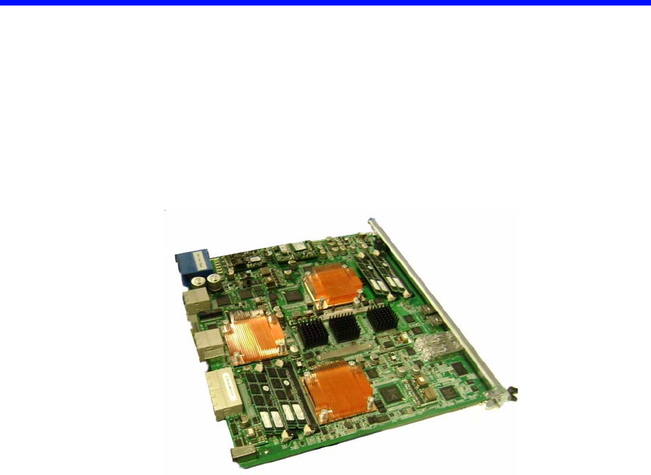
Figure 2-1: PP50 Overview Photo

Page 2-28
User Manual
Continuous Computing Corporation
FlexPacket ATCA PP50 Packet Processor
Preliminary
2.1 Main Features
The PP50’s major subsystems are described in this section.
2.1.1 RMI Processor Subsystem
The RMI processor subsystem includes dual RMI XLR7xx BGA1605 CPU sites; a
PP50 can support any CPU in any of those families with the proper assembly
changes. See Section2.2.5, "RMI Processor CPU Subsystem" for processor subsys-
tem details.
The RMI XLR processors support up to eight MIPS 64 bit RISC cores, each having 4
individual execution threads for a total of 32 execution threads.
See Table 2-1 "RMI XLR Family Configurations" for a reduced feature parts as list
for this processor family.
The PP50 supports reduced configurations based on these parts, but the default con-
figuration is two XLR732s fully populated devices.
2.1.2 Ethernet Switch Module
FM2112/FM3112 (Fulcrum Microelectronics) Ethernet switch module, described in
detail in Section2.2.6, "Fabric and Base Switch Modules". The onboard fabric
Ethernet and base Ethernet switches facilitate connectivity. The fabric switch is a
layer 2 device that provides 10GbE connectivity for the CPUs as well as multiple
1GbE data paths. The base switch facilitates communication between the two XLR
CPUs, IPMC controller and two base interfaces.
2.1.3 RTM Interface
The PP50 supports a rear transition module (RTM) that includes a protected power
supply, a management interface to the IPMC, ten 1GbE interfaces and two 10GbE
interfaces.
Page 2-29
CC06786-11B
Confidential and Proprietary
Technical Overview
1
4ABAB
Preliminary
2.2 Hardware Overview
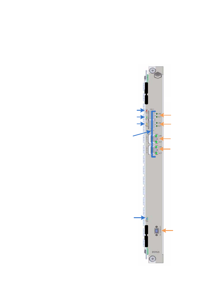
2.2.1 Front Panel Ports
•10GE.1: SFP+ port (IEEE 802.3 10GBASE-X)
• 10GE.2: SFP+ port (IEEE 802.3 10GBASE-X)
• CPU.1: RJ45 Connector to XLR 0
• CPU.2: RJ45 Connector to XLR 1
See Section2.2.10.1, "LEDs"for a description the LED indicators.
Figure 2-2: Front Panel
2.2.2 Backplane Interface
The PP50 is designed as a node board in an ATCA system. Its backplane interface is
compatible with the PICMG3.0 R2.0 specification.
OOS
IS
ATTN
H/S
LNK and ACT
LEDs Ports
10G 1
10G 2
CPU1
CPU2
CONSOLE

Page 2-30
User Manual
Continuous Computing Corporation
FlexPacket ATCA PP50 Packet Processor
Preliminary
2.2.3 Connectors
2.2.3.1 Internal Connectors
J15 - XLR CPU 2 Memory Channel AB Mini-DIMM Connector
J17 - XLR CPU 2 Memory Channel CD Mini-DIMM Connector
J18 - XLR CPU 1 Memory Channel AB Mini-DIMM Connector
J21 - XLR CPU 1 Memory Channel CD Mini-DIMM Connector
J52 - XLR CPU 2 CF card connector
J53 - XLR CPU 1 CF card connector
J54 - Extended JTAG connector from JTAG CPLD
J56 - JTAG connector for JTAG CPLD
J100 - Internal Mezzanine card connector
J101 - Internal Mezzanine card connector
J102 - JTAG connector for XLR CPU 1
J103 - JTAG connector for XLR CPU 2
J110 - JTAG connector for IPMC
2.2.3.2 External Connectors
J11 - Micro-DB9 Console Port
J104 - RJ45 Connector for XLR Module 1 (XLR0)
J105 - RJ45 Connector for XLR Module 2 (XLR1)
J109 - Two 10G SFP plus Ports connector
2.2.3.3 ATCA Connectors
P10 - ATCA Zone 1 Power Connector
J20 / J23 - ATCA Zone 2 connectors
J26 / J27 - ATCA Zone 3 connectors to RTM
Page 2-31
CC06786-11B
Confidential and Proprietary
Technical Overview
1
4ABAB
Preliminary
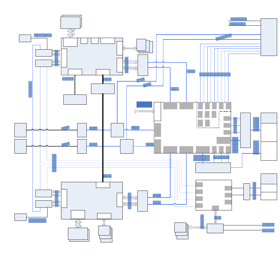
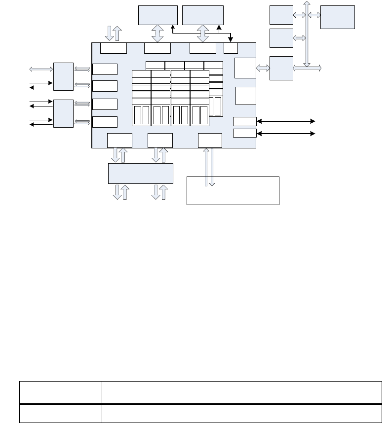
2.2.4 Graphical Overview
The following diagram provides a graphical overview the PP50’s hardware. The
zoom tool in your viewer may be used to magnify sections of interest.
Figure 2-3: Overall Hardware Block Diagram.
CF Flash
PSRAM
XLR732
)
DDRII DIMM
Four
GE MAC
Two 72bit
DRAM
interface
Two
10GE MAC
Local BUS
PCI- X BUS
Boot
Flash
SRAM /
LA-1
HT BUS
CF Flash
PSRAM
XLR732
DDRII DIMM
Four
GE MAC
Two 72bit
DRAM
interface L ocal BUS
Boot
Flash
SRAM /
LA-1
Two
10GE MAC
FM 2112
Core Switch
P1
P2
P24
Host Interface
P9
P4
P6
P3
P8
P5
P7 P13
P11
P15
P21
P19
P23
P22
P20
P18
P17
P10
P16
P14
P12
RGMII
TCAM or QDRII
Mezzanine
HT Co- processor
Mezzanine
LA-1
LA-1
HT 8bit
PM8380
MUX
SPF+
Module
PM8380
MUX
XUAI
XUAI
MUX
or Resistor
RESISTOR
XUAI or
1000 BASE- X
XUAI or
1000 BASE-X
1000BASE-X
1000BASE-X
SPF+
Module
SFI
SFI
XUAI
XUAI
RTM
2x10GE
10 x 1GE
Fabric
10GE
(or 4 x GE)
10GE
(or 4 x GE)
Channel 2
Channel1
BCM5389
Base Switch
P
P
P
P
P
P
P
P
VSC7280
Dual
XGMII-XAUI PHY
XGMII
VSC728 0
Dual
XGMII-XAUI PHY
XGMII
XUAI
XUAI
XUAI
XUAI
XUAI
XUAI
Base
Channel 1
Channel 2
BCM5482
1000 BASE-T
RJ45
RJ45
1000 BASE-T
1000 BASE-T
1000 BASE-X
1000 BASE-X
MII
I2C MDIO
I2C
MDIO
From IPMC
From IPMC
BCM5482
Dual PHY
BCM5482
Dual PHY
RGMII
BCM5482
Dual PHY
BCM5482
Dual PHY
AEL2005
BCM8706
16bit bus
405EZ
IPMC
Managed
by IPMC
IPMB A
IPMB B
FPGA
CRAM
FW2112
Page 2-32
User Manual
Continuous Computing Corporation
FlexPacket ATCA PP50 Packet Processor
Preliminary
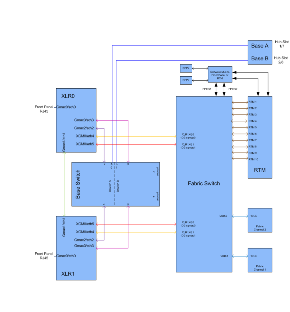
The diagram below shows connections between the PP50’s Base and Fabric
components.
Figure 2-4: Base and Fabric Connection Diagram.
Page 2-33
CC06786-11B
Confidential and Proprietary
Technical Overview
1
4ABAB
Preliminary
2.2.5 RMI Processor CPU Subsystem
Figure 2-5: RMI Processor CPU Subsystem
The PP50 uses two XLR7xx CPU sites. They are identical, except that the XLR at site
1 can access the co-processor mezzanine through the bus. The features of the CPU
subsystems are described below and shown in Figure 2-5 "RMI Processor CPU
Subsystem".
• RMI XLR7xx BGA1605 CPU sites; the PP50 can support any CPU in any of
those families with the proper assembly changes. They include the following
XLR Family of CPUs:
• Two 244 pin DDR2 Mini-DIMM sockets supporting standard 1.8V DDR2 Mini-
DIMMs
- One DIMM on memory channel A/B
- One DIMM on memory channel C/D
- Up to 800MHz DDR2 data rates
-Up to 4GB for each DIMM
Table 2-1: RMI XLR Family Configurations
Part x32
XLR7xx 8 Cores, 32threads four 1GbE; two 10GbE
C ompact
Flash
CORE5
THREAD 17
THREAD 18
THREAD 19
THREAD 20
ICache
DCache
CORE6
THREAD 21
THREAD 22
THREAD 23
THREAD 24
ICache
DCache
CORE7
THREAD 25
THREAD 26
THREAD 27
THREAD 28
ICache
DCache
CORE8
THREAD 29
THREAD 30
THREAD 31
THREAD 32
ICache
DCache
To TCAM
Mezzanine DDR2 DIMMDDR2 DIMM
RGMII A
RGMII B
RGMII C
RGMII D
GE MAC
GE MAC
GE MAC
GE MAC
SRAM /
LA-1 MEM AB MEM CD
10 GE
MAC
10 GE
MAC
XGMII A XGMII B
Local
BUS
PCI-X
BUS
UART 1
UART 2
HT BUS
Boot
Flash
Console Serial Port
Command Serial Port
CPU sub- system
To Co- Processor
Mezzanine
VSC7280
Dual XGMII- XAUI
XAUI A XAUI B
I2C
CORE1
THREAD 1
THREAD 2
THREAD 3
THREAD 4
ICache
DCache
CORE2
THREAD 5
THREAD 6
THREAD 7
THREAD 8
ICache
DCache
CORE3
THREAD 9
THREAD 10
THREAD 11
THREAD 12
ICache
DCache
CORE4
THREAD 13
THREAD 14
THREAD 15
THREAD 16
ICache
DCache
RAZA XLR
8bit
8bit
PSRAM
10/ 100/
1000 base-T
1000BASE-X
1000BASE-X
1000BASE-X
To Front
Panel
To the other
CPU module
To Base
Switch
To Core Switch To Core Switch
To Base
Switch
C ontrol
CPLD
(XLR1 Only)
BCM5482
Dual PHY
BCM5482
Dual PHY
Page 2-34
User Manual
Continuous Computing Corporation
FlexPacket ATCA PP50 Packet Processor
Preliminary
•LA-1 Interface
- Connected to a mezzanine for TCAM add on options
• Four RGMII Gigabit Ethernet interfaces
- One interface is routed to the front panel as the management port
- Two interfaces are routed to the base switch
- One interface to the other XLR through serial interface
• Two XGMII 10 Gigabit Ethernet interfaces routed to the Fabric Ethernet switch
• Local Bus / Peripheral Interface
- 8/16/32 bit devices, 66MHz
- Two 32M bytes FLASH for boot firmware
- CompactFLASH socket for additional storage
-Two 8MB PSRAM
- Control Complex Programmable Logic Devices (CPLD)
•Two UART Ports
- Port 1 connected to CNODE for FlexConsole
- Port 2 connected to CNODE as a command channel
• Two I2C Ports
- Port 1 connected to two Mini-DIMM sockets for SPD
- Port 2 connected to a serial EEPROM
2.2.5.1 PSRAM (Flight Recorder Memory)
Each XLR subsystem on the PP50 includes PSRAM (pseudo-static DRAM). I is
sometimes called flight recorder memory because it is unique in that it is not cleared
or initialized during board resets/reboots, so it can be used to preserve critical state
or logs across such events.
After a power cycle, the contents of the PSRAM are undefined. It is recommended
that a checksum, CRC, or some other data integrity check be used on the data in the
PSRAM to ensure that random powerup contents are not interpreted as valid data.
Typical uses for the PSRAM are to store routing tables, call routing information,
transaction checkpoints, or log files. Having these tables available in memory can
enable much faster application startup after a board reset or watchdog timeout.
Because the PSRAM is separate from main memory, neither the bootloader nor the
Linux kernel will disturb its contents. Note, that the bootloader PSRAM diagnostic
copies the contents to a safe area before testing the PSRAM, then copies the data
back in.
To access the PSRAM from RMIOS, you can simply configure a pointer to point to
the PSRAM base address and access it directly.

Page 2-35
CC06786-11B
Confidential and Proprietary
Technical Overview
1
4ABAB
Preliminary
To access the PSRAM from user level in Linux, use the mmap system call as shown
in the following code segment.
1. The start physical address and size of PSRAM on per XLR
Note, for PSRAM, the start address is 0x19000000, the size is 16384KB.
2. Call system API "mmap" to transform physical address to virtual address. For
example:
3. Then you can access PSRAM as same as accessing system memory.
PP50-1 $ iobus
IOBus Devices:
BaseAddr Size(KB) ChipSel Device
=============================================================================
0xbc000000 16384 0 cfiflash_0
0xb8000000 16384 3 cfiflash_1
0x19000000 16384 4 psram
0x1d000000 8192 6 pcmcia
0x1d840000 64 1 cpld
volatile u16 *psram_mmap(u32 addr, u32 size)
{
int fd=-1;
volatile u16 *mAddr=NULL;
if (0 > (fd = open("/dev/mem", O_RDWR|O_SYNC)))
{
if(debug)
{
printf("Open /dev/mem error!\n");
}
return NULL;
}
if (MAP_FAILED == (mAddr = mmap(NULL, size, PROT_READ|PROT_WRITE, MAP_SHARED,
fd, addr)))
{
if(debug)
{
printf("mmap /dev/mem error!\n");
}
close(fd);
return NULL;
}
close(fd);
return mAddr;
}
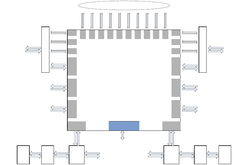
Page 2-36
User Manual
Continuous Computing Corporation
FlexPacket ATCA PP50 Packet Processor
Preliminary
2.2.6 Fabric and Base Switch Modules
Figure 2-6: Switch Module
The Ethernet data path is facilitated by a Fulcrum FM2112/FM3112 base and fabric
Ethernet switches. The FM2112/FM3112 contains eight 10GbE (4-lane) interfaces
and sixteen 1GbE (1-lane) interfaces. Any of the interfaces can be operated at two
speeds from two clocks, and the 4-lane ports can be operated as a single lane. The
clock input assignments for the Ethernet chip are:
• REFCLK_A (1-4) is 312.5MHz for 10GbE operation
• REFCLK_B (1-4) is 125MHz for 1GbE operation
FM2112
Core Switch
P1
P2
P24
Host Interface
P9
P4
P6
P3 P8
P5 P7
P13
P11 P15
P21 P19
P23
P22
P20
P18
P17
P10
P16
P14
P12
To IPMC
PM8380
MUX
XAUI
To RTM PM8380
MUX
XAUI
To RTM
To RAZA 1
To RAZA 1
To RAZA 2
To RAZA 2
XAUI XAUI XAUI
PHY PHY
SPF+
Module SPF+
Module
SFI SFI
XAUI or
1000BASE-X XAUI or
1000BASE-X
1000BASE-X
1000BASE-X
1000BASE-X
1000BASE-X
1000BASE-X
1000BASE-X
1000BASE-X
1000BASE-X
1000BASE-X
1000BASE-X
1000BASE-X
1000BASE-X
1000BASE-X
1000BASE-X
1000BASE-X
1000BASE-X
10 x 1 GE to RTM
MUX
MUX
10GE
(or 4 x 1GE)
10GE
(or 4 x 1GE)
To Fabric
Channel 2
To Fabri
Channel
1
XAUI
XAUI
XAUI
A
UI

Page 2-37
CC06786-11B
Confidential and Proprietary
Technical Overview
1
4ABAB
Preliminary
Possible operating modes for the switch are listed in Table 2-2 "Ethernet Switch
Operating Modes".
The fabric interface to the AdvancedTCA backplane can be configured for 10GbE or
four 1GbE operation. In 10GbE operation, Ports 7 and 5 are wired to all 4 ports in
channels 1 and 2. In four 1GbE operation, Ports 7 and 5 are put in 1GbE mode and
make up port [a] of the fabric interface. Switch ports [15 19 13] make up ports [b c d]
for channel 1, and likewise switch ports [21 11 9] make up ports [b c d] for Fabric
channel 2. The current allocation of the Fabric Ethernet ports are listed inTable 2-3
"Ethernet Switch Port Usage".
Table 2-2: Ethernet Switch Operating Modes
Port Lanes Speed Mode
1 – 8 4 3.125GHz 10GbE
1 – 8 1 3.125GHz 2.5GbE
1 – 8 1 1.25GHz 1GbE
9 – 24 1 1.25GHz 1GbE
Table 2-3: Ethernet Switch Port Usage
Internal Switch
Port Number-
ing
Port
Number-
ing
Port Label-
ing Speed Description
1 10GbE RAZA1
2FP-XG1/
RTM-XG1
10GbE Through a mux to RTM #1 or
Front panel #1
3 10GbE RAZA1 10G-B
4FP-XG2/
RTM-XG2
10GbE Through a mux to RTM #2 or
Front panel #2
5 10GbE Fabric Chan 2
6 10GbE RAZA2 10G-A
7 10GbE Fabric Chan 1
8 10GbE RAZA2 10G-B
9 1GbE Fabric Chan 2 Port D
10 17 RTM #3 1GbE 1GbE port
11 1GbE Fabric Chan 2 Port C
12 18 RTM #4 1GbE 1GbE port
13 1GbE Fabric Chan 1 Port D
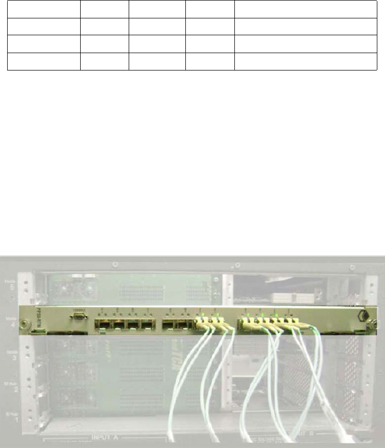
Page 2-38
User Manual
Continuous Computing Corporation
FlexPacket ATCA PP50 Packet Processor
Preliminary
2.2.7 Optional TCAM Mezzanine
The TCAM mezzanine is an optional factory-installed add-on board. For more infor-
mation about the TCAM, see the TCAM User Manual (CC07478).
2.2.8 RTM interface
The RTM is supplied with the PP50's primary 12V. The power budget for the RTM is
2.5A (30W) to support the requirement that the RTM slot support power dissipation
of up to 25W.
The 12V is supplied through a hot swap controller that limits the current and shuts
down the output upon a voltage or current fault. The controller is managed by the
CNODE.
14 19 RTM #5 1GbE 1GbE port
15 1GbE Fabric Chan 1 Port B
16 21 RTM #7 1GbE 1GbE port
17 15 RTM #1 1GbE 1GbE port
Figure 2-7: RTM interface in Chassis
Table 2-3: Ethernet Switch Port Usage
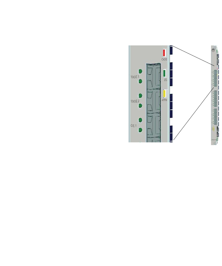
Page 2-39
CC06786-11B
Confidential and Proprietary
Technical Overview
1
4ABAB
Preliminary
RTM interfaces provide ten 1GbE ports and two 10GbE ports, supporting the RTM
options of ten SFP 1GbE ports or two 10GbE SFP+ ports. The switch configures the
1GbE ports to RTM in 1000 Base-X mode. These ports are isolated from the RTM
with capacitors.
Figure 2-8: RTM Panel
The CNODE controls activation of the RTM interface. The interface is designed such
that the RTM can be replaced in a running system without damage to the RTM or
the front board.
The PP50 RTM supports hot swap implementation where the RTM is reported as a
separate FRU, and deactivated without deactivating the front board. Only the ser-
vices using the RTM are deactivated. Consult the AdvancedTCA Specification for a
description of the hot swap sensor.
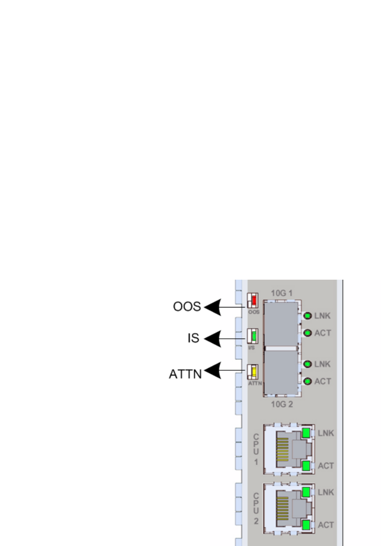
Page 2-40
User Manual
Continuous Computing Corporation
FlexPacket ATCA PP50 Packet Processor
Preliminary
2.2.9 Management Subsystem
The management subsystem in an AdvancedTCA blade is a mandatory feature,
required to always be on and supporting the system Intelligent Platform Manage-
ment Buses (IPMB). The CNODE, implemented with a PPC405EZ Microcontroller,
is required to support specific IPMI commands mandated by the AdvancedTCA
Specification. Also as required by specification, the CNODE controls the state of the
board (power and reset) and certain operator controls. The CNODE is required to
report, in FRU records, the connectivity of the board and other requirements, such
as its power needs.
Continuous Computing CNODE subsystems also provide additional core function-
ality for the blade. They provide a console MUX so a single RS-232 port on the front
can be used to access all internal devices, as well as additional sensors for better
operation of the board.
2.2.10 Front Panel
2.2.10.1 LEDs
As shown in Figure 2-9 "Front Panel LEDs", the front panel provides three working
status indicator LEDs which are defined in accordance with ATCA standards as Out
of Service (OOS), In Service (IS), and Attention (ATTN).
Figure 2-9: Front Panel LEDs

Page 2-41
CC06786-11B
Confidential and Proprietary
Technical Overview
1
4ABAB
Preliminary
Once the board is inserted in a slot and the primary 12V is powered on, a blue hot
swap indicator LED (HS) lights and then turns off when the board is completely
inserted.
Except for the blue LED, none of the remaining three LEDs are controlled by the
CNODE. Rather they are controlled by shelf manager and/or system management
applications by sending the IPMI command Set FRU Led State.
The front panel provides two working status indicator LEDs to each SFP+ port and
each 1GbE management port. One LED indicates link status (LINK) and the other
indicates active status (ACT).
LED functions are summarized below in Table 2-4 "LED Description".
Table 2-4: LED Description
LED Color Description
OOS Red Out Of Service LED. This LED is turned
ON when PP50 is powered ON and turned
OFF, when the FRU enters an M1 state.
After that this LED is supposed to be
controlled by Shelf Manager and/or
system management applications by
sending the IPMI command Set FRU Led
State.
IS Green In Service LED. This LED is turned ON
when PP50 is powered ON and then
turned OFF when FRU enters M1 state.
After that this LED is supposed to be
controlled by Shelf Manager and/or
system management application by
sending IPMI command Set FRU Led
State.
ATTN Yellow An alarm LED controlled by the onboard
shelf manager (if present). This LED is
turned ON when PP50 is powered ON and
then turned OFF when FRU enters M1
state. After that this LED is supposed to be
controlled by Shelf Manager and/or
system management application by
sending IPMI command Set FRU Led
State.
HS Blue HotSwap LED is controlled by IPMC as
per ATCA specification. LED illuminates
when it is safe to remove the board.

Page 2-42
User Manual
Continuous Computing Corporation
FlexPacket ATCA PP50 Packet Processor
Preliminary
2.2.10.2 Handle Switch
The front panel provides a handle switch to indicate whether the handle has been
pressed. Whenever the press action stops, the handle switch generates a reset indi-
cate to the CNODE.
2.2.10.3 Management Port
Each XLR processor has a RJ45 management port on the front panel.
2.2.10.4 Console Port
PP50 provides a console port to the front panel using a Micro-DB9.
2.2.10.5 10GBASE-X Port
PP50 provides two SFP+ ports at the front panel that comply with IEEE 802.3
10GBASE-X.
10GE1 LINK Green 10GE1 port link indicator, illuminates
when well linked.
10GE1 ACT Green 10GE1 port active indicator, illuminates
when activated
10GE2 LINK Green 10GE2 port link indicator, illuminates
when well linked.
10GE2 ACT Green 10GE2 port active indicator, illuminates
when activated
XLR0 GMAC0
LINK
Green XLR0 gmac0 port link indicator,
illuminates when well linked
XLR0 GMAC0
ACT
Green XLR0 gmac0 port active indicator,
illuminates when activated
XLR1 GMAC0
LINK
Green XLR1 gmac0 port link indicator,
illuminates when well linked
XLR1 GMAC0
ACT
Green XLR1 gmac0 port active indicator,
illuminates when activated
Table 2-4: LED Description
LED Color Description

Page 2-43
CC06786-11B
Confidential and Proprietary
Technical Overview
1
4ABAB
Preliminary
2.2.11 Jumpers
2.2.11.1 Default Jumper Settings
By default no jumpers are installed on the PP50.
Table 2-5: PP50 Jumper Information
Jumper Function Default Settings
J28 XLR CPU 2 EEPROM
Write Enable
Not Installed • Installed: XLR EEPROM
is write enabled
• Not Installed: EEPROM
is write protected
J29 XLR CPU 1 EEPROM
Write Enable
Not Installed
J111 Serial Mode Control 0
(S0)
Not Installed • Use the settings for
J111, J112, and J113 below
to configure the serial
mode.
“ 0” means installed,
“1” means not installed
The digits represent
S0, S1, and S2
respectively:
•1 1 1
Default, IPMC UART's
signals goes to front-
panel console pins
• 0 1 0
Multiplex IPMC UART,
XLR0/XLR1 'console'
ports on front panel
•0 0 1
Multiplex IPMC UART,
XLR0/XLR1 'command'
ports on front panel
•OTHERS: reserved
J112 Serial Mode Control
1(S1)
Not Installed
J113 Serial Mode Control 2
(S2)
Not Installed
J115 Force to reset payload
domain parts
Not Installed • Installed: Reset payload
• Not Installed: Normal
Operation

Page 2-44
User Manual
Continuous Computing Corporation
FlexPacket ATCA PP50 Packet Processor
Preliminary
2.2.11.2 Force Power On Jumper: J116
By default this jumper is open and the power is controlled by the CNODE. The pri-
mary 12V power turns on as soon as A_OK or B_OK is true indicating that one of
the 48V feeds is in range.
When the jumper is installed, the secondary power turns on as soon as the primary
12V is in range. This is regardless of the state of any CNODE control. Also, the sec-
ondary fault latch-off feature is disabled so the board will remain powered even if
one of the supplies is not in range. This feature should be used carefully.
J116 Force Payload Power
On
Not Installed • Installed: Force blade
power on [ignores IPMC]
• Not Installed: Normal
operation - IPMC
controls power on/off
J117 Select XLR0 Boot
Flash Bank
Not Installed • Installed: XLR0 boot
from the first bank
• Not Installed: XLR0 boot
from the second bank
J118 Select XLR1 Boot
Flash Bank
Not Installed • Installed: XLR1 boot
from the first bank
• Not Installed: XLR1 boot
from the second bank
J119 Force to reset
CNODE module
Not Installed • Installed: Reset CNODE
module parts
• Not Installed: Normal
Operation
Table 2-5: PP50 Jumper Information
Jumper Function Default Settings

Page 2-45
CC06786-11B
Confidential and Proprietary
Technical Overview
1
4ABAB
Preliminary
2.2.11.3 Console Mux Bypass Jumpers: J112, J113
The following jumpers allow reconfiguration of the front panel console, redirecting
it to one of the CPU ports. This allows console access before the IPMC console MUX
code is available. See Section2.2.11, "Jumpers" for further details.
In triple output mode, two of the payload data leads are multiplexed onto the
modem control pins.
During any of the debug modes, the other UARTs remain connected normally. In
modes 1-4 (single UART bypassed), the modem control signals are driven to active
states. The inputs are ignored.
2.2.11.4 Spare Serial Config Jumper: J111
Since only three serial configurations are needed on this board, J111 is reserved for
future use.
2.2.11.5 Alt Boot Bank Select Jumpers: J117, J118
By default this jumper is open and _BANK_SEL and _SEL(2) for XLR0 and XLR1 are
controlled from the CNODE.
Table 2-6: Console Debug Bypass
S1 (J112) S0 (J113) Front Panel Function
Open Open UART 1 Normal Operation
Open Inst MUX1 Triple Output 1
Inst Open MUX2 Triple Output 2
Inst Inst Does not work Reserved
Table 2-7: Debug Mode – Triple MUX Modes
FP Connector Pin MUX 1 Mode MUX 2 Mode
TxD PPC405 UART1 TxD PPC405 UART1 TxD
RxD PPC405 UART1 RxD PPC405 UART1 RxD
RTS XLR0 Console TxD XLR0 Command TxD
CTS XLR0 Console RxD XLR0 Command RxD
DTR XLR1 Console TxD XLR1 Command TxD
DSR XLR1 Console RxD XLR1 Command RxD

Page 2-46
User Manual
Continuous Computing Corporation
FlexPacket ATCA PP50 Packet Processor
Preliminary
When installed, BOOT_BANK_SEL or BOOT_BANK_SEL2 are forced HIGH to
select the second bank. The initial state of these lines is LOW until modified by the
CNODE. This allows the second bank to be tested.
2.2.11.6 Reserved Jumpers
2.2.12 Power Design
The PP50 Blade supports ATCA standard dual -48V power inputs. The input power
monitor is set to shut off if any of the following conditions are met or exceeded:
• Input current meets or exceeds 5 Amps
• Input voltage is less than -38V
• Input voltage is greater than -75V
In addition to the -48V input monitoring, a hold-up circuit is provided to give 5ms
of hold-up voltage on the input to system power supplies if the input power is shut
off.
2.2.13 Mean Time Between Failures
The mean time between failure (MTBF) rate for the PP50 front board is 116,347
hours and 1,081,629 hours for the RTM.
Table 2-8: Reserved Jumpers
Jumper Function Default
J30 Reserved for Factory Test Not Installed
J31 Reserved for Factory Test Not Installed
J32 Reserved for Factory Test Not Installed
J33 Reserved for Factory TesT Not Installed
J34 Reserved for Factory Test Not Installed
J35 Reserved for Factory Test Not Installed

Page 2-47
CC06786-11B
Confidential and Proprietary
Technical Overview
1
4ABAB
Preliminary
2.3 Component Integration Overview
Depending on the configuration, software for the PP50 may include a variety of
firmware, utilities, development environments, libraries, demonstration apps, and
diagnostics. While customized software applications and protocol stacks can run on
the PP50, they are not part of the core product and are not covered in this document.
2.3.1 Firmware
The PP50 firmware falls into the following categories.
Table 2-9: PP50 Major Firmware Categories
Component Description
IPMI/IPMC
Firmware
Firmware run by the IPMC
XLR
bootloader
The bootloader for the XLR packet processors, with
customizations and extensions by Continuous Computing for
better manageability.
XLR
diagnostics
Extensions to the XLR_Diagnostics to support hardware bring up
and verification.
XLR linux
image
A bootable filesystem based on the one provided by RMI, but
with copies of Continuous Computing demos, diagnostics, and
utilities included.
XLR MIPS
development
environment
The gcc, gdb, libtools, and other utilities for building software
applications that run on the XLR. These tools are generally
available both in x86-hosted cross versions and native on the
XLR linux image.
PP50 Host
Tools
Any tools or utilities intended to run on another host for
configuring or managing the PP50. This includes image
downloaders, etc.

Page 2-48
User Manual
Continuous Computing Corporation
FlexPacket ATCA PP50 Packet Processor
Preliminary
2.3.2 IPMI
The PP50 uses the industry standard IPMI (Intelligent Peripheral Management
Interface) for communication as mandated by the IPMI standard versions 1.5 and
2.0.
For a list of optional and mandatory IPMI commands supported by the PP50, see
Chapter7, "Intelligent Platform Management Controller" for details.
Per IPMI standards, the PP50 IPMC (Intelligent Peripheral Management Controller)
controls the blade and communicates through the Intelligent Peripheral Manage-
ment Bus (IPMB). The IPMB consists of dual independent buses that connect to all
the system boards, including the shelf manager, through the chassis midplane.
Also connected to the IPMC is the FRU inventory eeprom. That eeprom stores the
PP50’s serial number, part number, manufacture date, MAC address and other criti-
cal identifying information.
When a PP50 is plugged in, the shelf manager can be queried to ensure the correct
blade has been inserted and may be safely powered up. Shutdown is also coordi-
nated between the CNODE and shelf manager when a PP50 is ejected from the
chassis.
2.3.3 IPMC
The IPMC is responsible for important functions, such as turning power on and off
and monitoring the power levels. Specifically, it coordinates with redundant shelf
managers to check if all the power converters are working correctly, voltages are
within their proper thresholds, and temperatures are within safe ranges.
Figure 2-10 diagrams the IPMC topology. At the base of the IPMC is the universal
bootloader (uboot). A Linux kernel runs on top of that. Above the kernel is the
IPMC and base and fabric software management. For the most part, these compo-
nents require no input or customization.
.
Figure 2-10: IPMC Overview
IPMC Base SW
Management
Fabric SW
Management
Linux Kernel
uboot
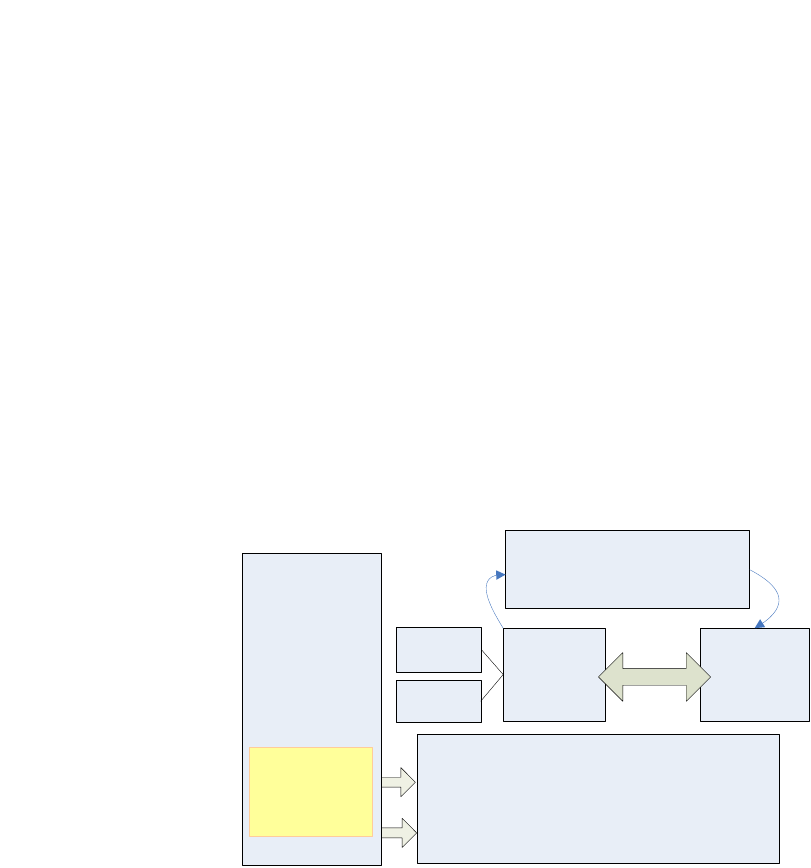
Page 2-49
CC06786-11B
Confidential and Proprietary
Technical Overview
1
4ABAB
Preliminary
2.3.4 IPMC and XLR Software Domains
Each PP50 has two XLR processors and an IPMC, each with its own software
domain. Continuous Computing provides the proprietary code for the IPMCs. Gen-
erally speaking, Continuous Computing customers will have no need to change the
IPMC code.
2.3.5 XLR Watchdog Timers
There are two watchdog timers in the IPMC to monitor each XLR's booting process.
Users can enable the watchdog timers by setting the associated KV values
s0_bootwd and s1_bootwd.
The key value s0_bootwd and s1_bootwd save the XLR boot time (units in seconds).
When the XLR0 OS cannot boot up in the KV s0_bootwd time, the IPMC will reset
XLR0 and log its reset cause and reset time in the KV __s0_rstcause and
__s0_rsttime.
XLR1 also follows the same procedure except that it uses s1_bootwd, __s1_rstcause,
and __s1_rsttime. The KV 'sobootwd' and 's1bootwd' are created by default.
The watchdog timer is particularly useful when using the multiboot, see Sec-
tion6.2.1, "Continuous Computing Multiboot" for details.
2.3.6 XLR Software
The PP50 maximizes the XLR’s two 10GbE network interfaces and processing
power (8 cores, 4 threads each, 32 virtual processors).
Figure 2-11: XLR Software Overview
Linux RMIOS
XLR BootLoader
Package Filename: PP50-xlr-boot-V X.Y.Z.B
Based on RMI bootloader modified for the PP50
RMI
SDK
WRPNE
RMI
Linux 1-N 8-N
Control Data Fastpath
Linux Kernel
CCPU modified
Bootloader
PP50 Specific
Shared
Memory
Interface
Linux Apps
Linux Loader
userapp

Page 2-50
User Manual
Continuous Computing Corporation
FlexPacket ATCA PP50 Packet Processor
Preliminary
Referring to Figure 2-11, note that the XLR Bootloader’s package uses the naming
convention pp50-xlr-boot-vx.y.z.bin. The package is based on the RMI bootloader,
but has been modified to run on the PP50. Standard unmodified RMI bootloaders
will not run on PP50s. Requests for enhancements to the bootloader should be made
to Continuous Computing. They will be included in qualified releases.
The RMI SDK in this context should only be used as reference code for building
PP50 applications. Unmodified RMI SDK code cannot be directly used in PP50
applications.
A common option is to run, on top of the XLR bootloader, Linux on 1-N cores of the
XLRs and the RMIOS on the other 8-N cores. Operating systems typically are run on
a per core basis. Running them on a per thread basis is possible but not
recommended.
Typically, Linux threads are used to run control software such as call management,
bandwidth allocation and load balancing. RMIOS threads are used to take packets
in and send them out (fastpath, 10 Gb interface). A shared memory interface allows
the Linux threads to communicate with the RMIOS threads. The RMIOS comes from
the RMI SDK with little modification.
The Linux loader application runs on top of the Linux OS. It primarily runs the user-
app command. The userapp command loads and unloads RMIOS programs from
within Linux. Linux running on core one can tell the userapp command to load
RMIOS on the other seven cores and to start.
Note: The Linux OS, bootloader RMIOS, and Linux loader application
being run on a PP50 must all come from the same version of the
SDK.
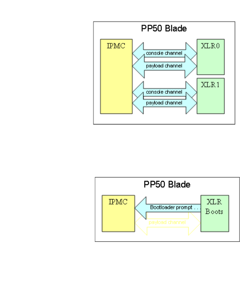
Page 2-51
CC06786-11B
Confidential and Proprietary
Technical Overview
1
4ABAB
Preliminary
2.3.7 XLR and IPMC Messaging
The IPMC communicates with each XLR (sometimes referred to as payload)
through two serial ports. One port is the console channel, the other is the payload
channel.
Figure 2-12: XLR and IPMC Messaging
When the XLRs boot, they send information such as the boot loader prompts and
kernel bootloader strings to the IPMC through the console channel.
Figure 2-13: XLR and IPMC Boot Messaging
Users access the XLRs from this console channel. They telnet through the network to
the IPMC and request connection to XLR0 or XLR1.

Page 2-52
User Manual
Continuous Computing Corporation
FlexPacket ATCA PP50 Packet Processor
Preliminary
Figure 2-14: XLR and IPMC Telnet Messaging
The payload channel is an IPMI messaging channel. The payload sends IPMI mes-
sages in a serialized format to the IPMC. The IPMC then responds to those
messages. For example, when the XLR wants to strobe its watchdog, it sends a
strobe watchdog message over the payload channel that resets the watchdog timer.
Figure 2-15: XLR and IPMC IPMI Messaging
The PP50’s IPMC also handles several other functions. In this document, the IPMC
plus these other functions are referred to collectively as the CNODE.
An important function of the CNODE is its internal base switching. Because the
ATCA standard only allows two base ports per blade (one to each of the switches in
a chassis), normally only one XLR could have access to the switches at a time. To
overcome this limitation and be consistent with High Availability (HA) principles,
an internal base switch was created on the PP50. This base switch is partitioned to
look like it has two base switches. Each XLR gets a virtual base; consequently, each
XLR has access to both base ports and switches using different GMACs.
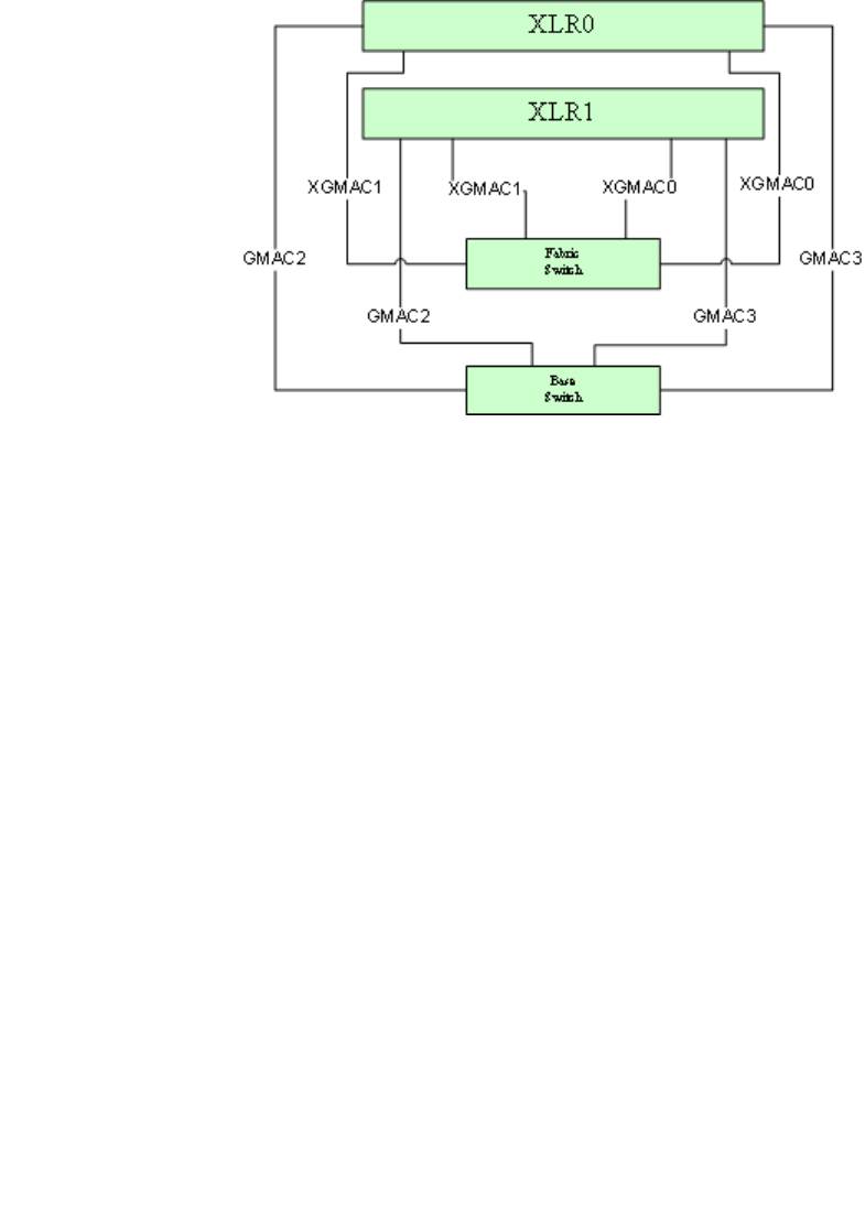
Page 2-53
CC06786-11B
Confidential and Proprietary
Technical Overview
1
4ABAB
Preliminary
Figure 2-16: Virtual Switches
The CNODE also handles base switch configuration and management. All base
switch connectivity for the PP50 is handled through this switch.
A fabric switch on the PP50 helps avoid a similar constraint on the fabric plane. The
midplane has two 10Gb interfaces. Connecting one interface to each payload would
not allow redundancy for HA. Like the base switch mentioned above, the fabric
switch is partitioned into two virtual switches. Each of those midplane ports goes to
one half of the fabric switch and each of the XLRs has connections to the fabric
switch. Either XLR can get to either half of the fabric switch, and thus can get to
either one of the fabric ports on the midplane.
Both the fabric and base ports connect to hub one and two via the midplane to
access the chassis switches.
2.3.8 Power Domains
The PP50 has two power domains, management and payload. The management
domain powers components of the PP50 that manage the board. The payload
domain powers components associated with the payload. When a board is plugged
in, the management domain is powered up first to ready the blade for operation.
Once the PP50 is ready for full operation, the payload domain is powered up.
The CNODE is on the management power domain. As soon as a PP50 is plugged in,
the management domain is powered up and functioning. The base switch comes up,
then CNODE comes up and starts the IPMC, which queries the shelf manager
whether to start the PP50’s payload power domain. If it gets an OK, the CNODE
starts up the payload domain.
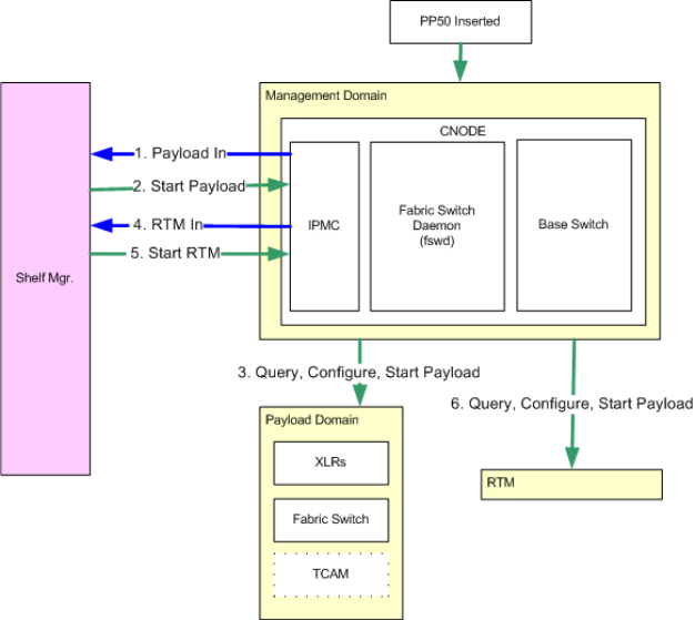
Page 2-54
User Manual
Continuous Computing Corporation
FlexPacket ATCA PP50 Packet Processor
Preliminary
It is important to note that the fabric switch manager is part of the payload power
domain. Therefore, the fabric switch and XLRs only start after the CNODE signals
the fabric switch manager to power on.
The CNODE signals the fabric switch manager to power on through a daemon,
which runs a script that configures the fabric switch when the payload domain is
activated. The daemon also monitors the fabric switch for proper functioning. For
example, if a link is disconnected and reconnected, the switch responds appropri-
ately and the link continues to work uninterrupted.
Figure 2-17: Power Domains, Startup
The fabric switch may also be custom configured to do things such as change traffic
flow, handle VLANs, and direct certain packets to specific boards or payloads. A
detailed description of fabric switch configuration is provided later in this
document.
Page 2-55
CC06786-11B
Confidential and Proprietary
Technical Overview
1
4ABAB
Preliminary
2.4 Specifications
2.4.1 CPU / Memory
• 1 or 2 RMI XLR732 processors
• 1GHz multi-core MIPS64, 8 multi-threaded cores (32 virtual cores)
• 2MB of 8-way set associative L2 cache
• 2GB, 4GB, or 8GB DDR2 memory per processor
2.4.2 Input/Output
• Dual redundant 1GbE base interface
• 10GbE & 1GbE fabric interfaces (PICMG 3.1.9 - 10GbE and PICMG 3.1.3 - 1GbE)
• 2 x 10GbE on front panel
• RJ45 1GbE front panel management port
2.4.3 Expansion Options
• 36Mbit or 72Mbit TCAM mezzanine using Netlogic NL71024
• Optional 1Gb or 2Gb CompactFlash per processor
• OEM Rear Transition Module(s)
- 2 x 10GbE (SFP+)
- 10 x 1GbE (SFP)
2.4.4 Software
• Wind River Linux PNE
• RMI Operating System (Native C-based OS for fast path)
• Network and routing protocols including fast path and slow path functions
- Includes IPv4/6 forwarding, IPSEC, Tunneling, GRE, etc.
2.4.5 Mechanical & Environmental Compliance
• Standard 8U single-slot (6 HP) front board and RTM
• Operating environment:
- Temperature: 0C to +55C
- Humidity: 5%-80% (non-condensing)
- Vibration: 20Hz-2KHz random multi-axis, 0.5G RMS

Page 2-56
User Manual
Continuous Computing Corporation
FlexPacket ATCA PP50 Packet Processor
Preliminary
• Storage/transportation environment:
- Temperature: -40C to +85C
- Humidity: 5%-95% (non-condensing)
- Vibration: 20Hz-2KHz random multi-axis, 6G RMS
Assembly components meet UL 94-V0 flammability rating.
2.4.6 Fuses
2.4.7 Certifications
• UL 60950-1 Safety of Information Technology Equipment , UL File# E204665.
2.4.7.1 Planned Certifications
• IEC/EN 60950-1 Safety of Information Technology Equipment.
• FCC Part 15, Subpart B, Class A.
•CE Mark - Meets EMC directive 89/336/EEC.
• Designed for Telcordia NEBS GR-63-CORE and GR-1089-CORE Level 3.
• RoHS 6 / 6 Compliant.
2.4.8 Power Consumption
When the PP50 is installed with no test software running, the power consumption is
126 watts. Actual power consumption may vary depending on specific application.
Contact your sales rep for detailed power consumption reports.
Table 2-10: Fuse Specification
Location Continuous
Computing
PN
Fuse Character-
istics
FUSE Nomi-
nal Melting
I2t A2 Sec Manufacturer PN
F1, F2 3-01304 Surface Mount
Fuse, 12A, 65V
47.59 Littelfuse
Incorporated
(448012)
F3, F4 3-01302 Surface Mount
Fuse, 15A, 65V
96.10 Littelfuse
Incorporated
(448015)
F5, F6 3-01303 Surface Mount
Fuse, 1A, 125V
0.441 Littelfuse
Incorporated
(448001)

Page 3-57
CC06786-11B
Confidential and Proprietary
3
Preliminary
3Board Installation
This chapter describes the precautions to take when planning an installation, the
conditions which must be met and how to physically install a PP50 into your chassis
in the following sections.
•Section3.1, "Precautions"
•Section3.2, "Unpacking the PP50"
•Section3.3, "Installing PP50s into the Chassis"

Page 3-58
User Manual
Continuous Computing Corporation
FlexPacket ATCA PP50 Packet Processor
Preliminary
3.1 Precautions
3.1.1 Environmental Requirements
Requirements for the indoor working environment of the equipment:
• Temperature: 0oC - 55oC
• Relative humidity: 10% - 90% (non-condensing)
• Air pressure: 70 kPa - 105 kPa (70 kPa is equal to the air pressure at the altitude
of 3000 m)
3.1.2 Heat Dissipation and Dust Prevention
• Always place the board in a clean environment with good ventilation.
• The installation site should be far away from radiator or heat sources, and free
of conductive dust, corrosive gases and explosives.
• Do not operate your system in dusty environments. This will clog the filters
and lower the cooling efficiency.
3.1.3 Electrostatic Prevention
Static electricity can harm delicate components. To prevent static damage, discharge
static electricity from your body before you touch any components. You can do so
by wearing an antistatic wrist strap.
Caution: Always maintain an ESD-safe environment during the installation,
many components can be destroyed by ESD.

Page 3-59
CC06786-11B
Confidential and Proprietary
Board Installation
1
4ABAB
Preliminary
Remember to wear an antistatic wrist strap during equipment installation and
debugging.
Figure 3-1: ESD Wrist Strap
You can also take the following steps to prevent damage from electrostatic
discharge:
• When unpacking a static-sensitive component from its shipping carton, do not
remove the component from the antistatic packing material until you are ready
to install the component. Just before unwrapping the antistatic packaging, be
sure to use a grounding strap to discharge static electricity from your body.
• When transporting a sensitive component, first place it in an antistatic container
or packaging.
• Handle all sensitive components in a static-safe area. If possible, use antistatic
floor pads and workbench pads.
3.1.4 Other Precautions
• Do not block the heat-dissipating vents of the equipment.
• Position the equipment in a stable location to avoid strong vibration.
• Prevent the equipment from hitting or rubbing other equipment to avoid
surface damage.
• Keep your system away from radiators and heat sources.
• Do not block air intake or air exhaust vents.
• Be sure nothing rests on cables and that the cables are not located where they
may be stepped on or tripped over.
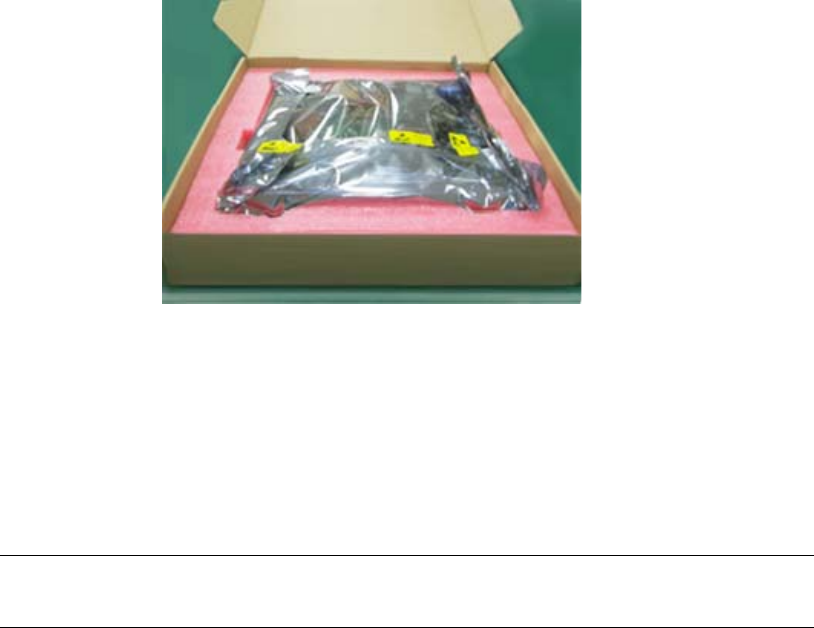
Page 3-60
User Manual
Continuous Computing Corporation
FlexPacket ATCA PP50 Packet Processor
Preliminary
3.2 Unpacking the PP50
The following photo shows generic PP50 packaging. Your packaging may vary
depending on such variables as specific options chosen and country of delievery.
Figure 3-2: PP50 Unpacking
When unpacking inspect for the following:
• Check the number of items against the dispatch list.
• If anything is damaged or missing, immediately follow the procedures in
Appendix13, "Product Repair and Returns" or contact our After-Sales Service
Center.
3.2.1 Compact Flash
Do not remove the compact flash cards. They protect the connector pins from dam-
age. If the board is handled without the flash modules, the pins can bend, short, and
the interface can be permanently damaged. Flash cards may be replaced with a dif-
ferent card but not leave the socket empty.
Note: Only personnel experienced with installing telecommunication
equipment should unpack and install these boards.
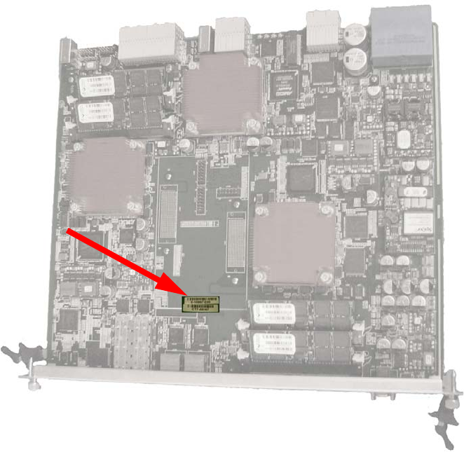
Page 3-61
CC06786-11B
Confidential and Proprietary
Board Installation
1
4ABAB
Preliminary
3.2.2 Board Identification
3.2.2.1 Serial Number
PP50s may be identified by the board serial number as shown below.
Figure 3-3: Serial Number Location

Page 3-62
User Manual
Continuous Computing Corporation
FlexPacket ATCA PP50 Packet Processor
Preliminary
3.2.2.2 MAC Address
Each PP50 board is has 16 MAC addresses. All have a 00:02:bb:50 prefix. The lowest-
numbered address is the BASE address and always ends in '0' (hex). Each network
port on the PP50 board is a fixed offset from the BASE address as described below.
Table 3-1: MAC Address Ports
Chip Address eth Port Example
XLR0 BASE+0 eth0 gmac0 00:02:BB:50:2A:80
BASE+1 eth1 gmac1 00:02:BB:50:2A:81
BASE+2 eth2 gmac2 00:02:BB:50:2A:82
BASE+3 eth3 gmac3 00:02:BB:50:2A:83
BASE+4 eth4 10G xgmac0 00:02:BB:50:2A:84
BASE+5 eth5 10G xgmac1 00:02:BB:50:2A:85
IPMC BASE+6 eth0 Base Network 1 00:02:BB:50:2A:86
eth0.4094 Base Network 1 (Alias) 00:02:BB:50:2A:86
BASE+7 Reserved Base Network 2
XLR1 BASE+8 eth0 gmac0 00:02:BB:50:2A:88
BASE+9 eth1 gmac1 00:02:BB:50:2A:89
BASE+A eth2 gmac2 00:02:BB:50:2A:8A
BASE+B eth3 gmac3 00:02:BB:50:2A:8B
BASE+C eth4 10G xgmac0 00:02:BB:50:2A:8C
BASE+D eth5 10G xgmac1 00:02:BB:50:2A:8D
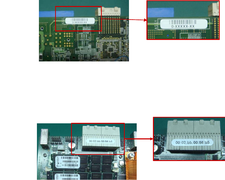
Page 3-63
CC06786-11B
Confidential and Proprietary
Board Installation
1
4ABAB
Preliminary
3.2.2.3 Part Number
The PP50s part number may be found in the location shown below.
3.2.2.4 MAC Address Location
The PP50s MAC address may be found in the location shown below.
3.2.2.5 IPMI Manufacturing Info
The IPMI GetDeviceInfo command specifies each device return a manufacturer and
product ID field. The manufacturer field is three bytes and contains Continuous
Computing’s IANA OUI (7994) in a binary representation (0x001F3A, represented
little-endian in the actual IPMI response as 0x3A, 0x1F, 0x00).
• IPMI Manufacturer ID: 0x001F3A (7994)
• IPMI Product ID: 0xBB50
Figure 3-4: Part Number Location
Figure 3-5: MAC Address Location
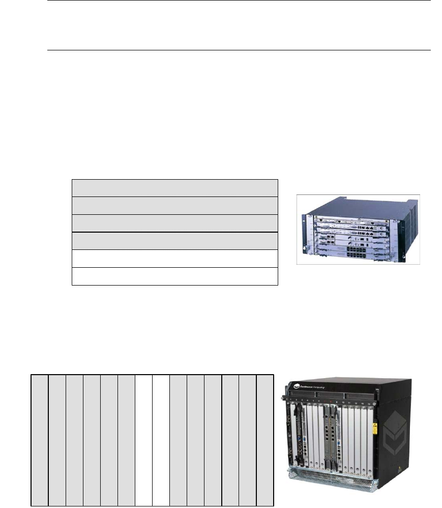
Page 3-64
User Manual
Continuous Computing Corporation
FlexPacket ATCA PP50 Packet Processor
Preliminary
3.3 Installing PP50s into the Chassis
3.3.1 Where to Install the PP50
The PP50 board can be installed in the node slot of any ATCA compatible chassis. In
Continuous Computing’s 5U and 12U chassis, the PP50 should be installed in the
slots shown in the following figures. For chassis details, please refer to their respec-
tive user manuals.
Figure 3-6: 5U Chassis Slots
Figure 3-7: 12U Chassis Slots
Caution: Air blockers must be installed into all vacant slots to ensure
proper air flow and cooling for the blades, Operation without air
blockers in all empty slots voids the warranty.
Node Slot
Hub Slot
Node Slot
Node Slot
Node Slot
Hub Slot
Slot 1
Slot 2
Slot 3
Slot 4
Slot 5
Slot 6
Node Slot
Node Slot
Node Slot
Node Slot
Hub Slot
Node Slot
Node Slot
Hub Slot
Node Slot
Node Slot
Node Slot
Node Slot
Node Slot
Node Slot
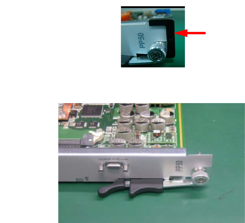
Page 3-65
CC06786-11B
Confidential and Proprietary
Board Installation
1
4ABAB
Preliminary
3.3.2 Board Insertion
1. If present, remove black end caps.
2. Disengage the latch handles as follows.
a. Place the board on an ESD-safe work surface.
Figure 3-8: Latch Handle
b. Grip both the handles with your thumbs and index fingers.
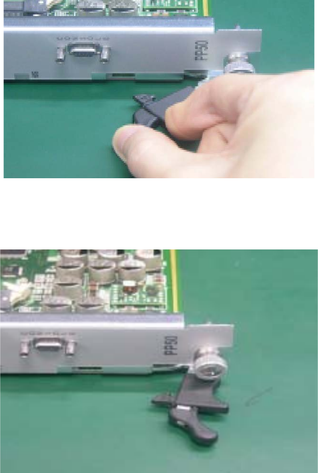
Page 3-66
User Manual
Continuous Computing Corporation
FlexPacket ATCA PP50 Packet Processor
Preliminary
c. To disengage the locking mechanisms, firmly squeeze the lever portions of
both handles simultaneously, pressing them toward their respective
locator pins. At the same time, pivot the handles out away from the board
as shown below.
Figure 3-9: Opening the Latch Handle, Lever Release
d. Release the handles once they have cleared the slot/catch, and continue to
pivot the handles outward until they are at a 90 degree angle from their
original positions as shown in Figure 3-10.
Figure 3-10: Opened Latch Handle
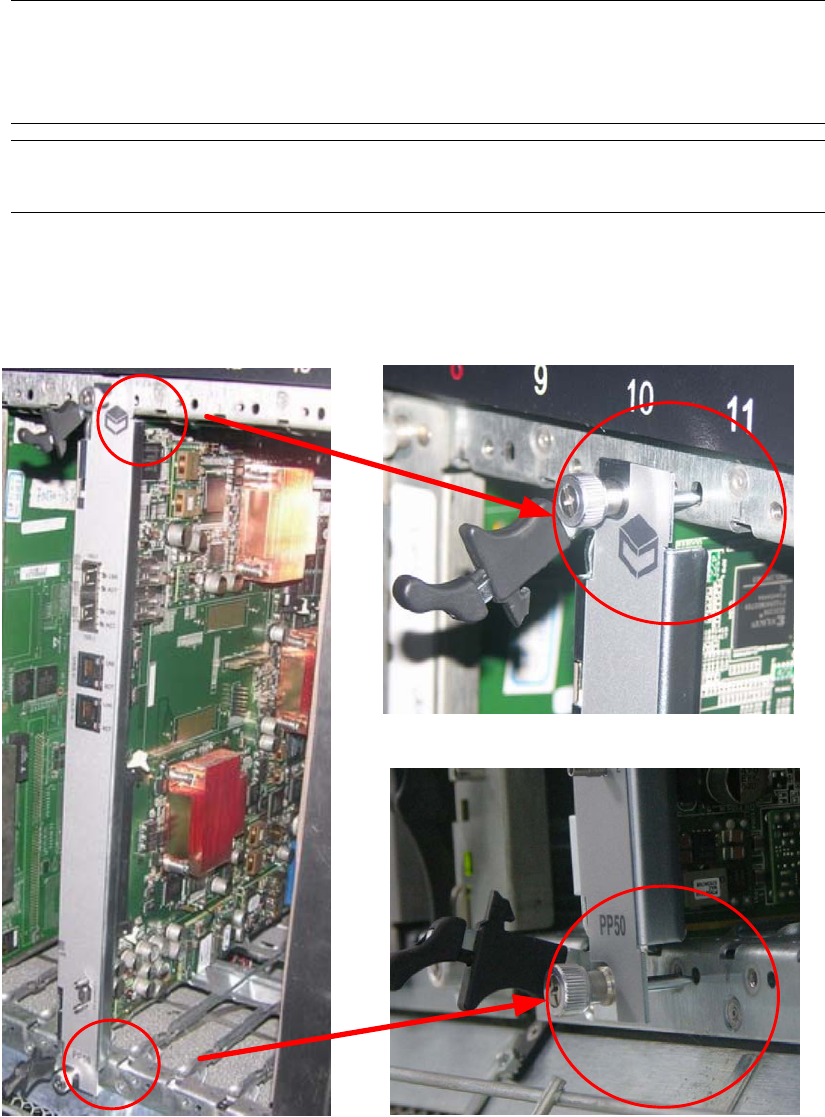
Page 3-67
CC06786-11B
Confidential and Proprietary
Board Installation
1
4ABAB
Preliminary
3. Carefully begin inserting the board into the desired slot within the chassis.
- Grip the board anywhere on its faceplate during this process, except the
handles.
- Line up the locator pins at both ends of the board to the locator pinhole/
guide on the chassis.
Figure 3-11: Installation - Locator Pins
Caution: Be careful when installing the boards into the chassis. The board
handles can be shaved off when they are inserted through the cutout.
Components can be destroyed because of improper insertion
technique. Do not use force.
Caution: Take care not to bend the connector pins as you remove and install the
board.
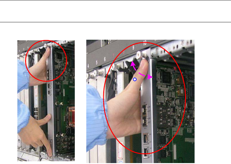
Page 3-68
User Manual
Continuous Computing Corporation
FlexPacket ATCA PP50 Packet Processor
Preliminary
4. Once the locator pins are aligned with the pin holes/guides, slowly press the
board further in.
- Position hands/thumbs as shown to ensure the locator pins remain in
alignment with their holes/guides.
- Do not hold the handles during this insertion process; allow them to move
freely.
- Stop this insertion process once the handles are roughly 45 degrees from
the front of the faceplate.
Figure 3-12: Installation - Board Insertion
Note: Although only the top handle is shown in the illustrations, both
handles must be at a 45 degree angle.
45 C
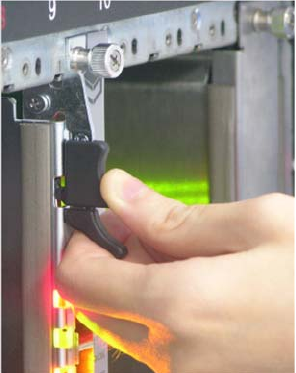
Page 3-69
CC06786-11B
Confidential and Proprietary
Board Installation
1
4ABAB
Preliminary
5. Engage the handles.
- Squeeze both the top and bottom handles simultaneously, and hold. Then,
loosely and carefully insert the tip of each handle’s catch into the slot. Be
careful not to hit the slot edges to avoid damage to the handle.
- Once you are certain the alignment is correct, while still squeezing the
handles, engage the latches fully. Ensure that the handles are fully engaged
by pressing them in firmly.
Figure 3-13: PP50 Installation - Board Insertion, Latch Closure
- The blue HS (Hot Swap) LED on the face-plate (near lower handle) should
illuminate, and then blink. After a few moments, it should turn off. If this
doesn’t happen, back the handle out slightly then re-engage.
6. Tighten the front panel thumb bolts with a screw driver to secure it to the
chassis. Failure to do so may result in improper board behavior.
3.3.3 Air Blocker Modules in Vacant Slots
Air blockers must be installed into all vacant slots to ensure proper air flow and
cooling for the blade, Operation without air blockers in all empty slots voids the
warranty.
Page 3-70
User Manual
Continuous Computing Corporation
FlexPacket ATCA PP50 Packet Processor
Preliminary

Page 4-71
CC06786-11B
Confidential and Proprietary
4
Preliminary
4Board Access, Bootup, and Shutdown
This chapter describes how to access, boot up, shutdown, and reset the PP50 in the
following sections.
•Section4.1, "Serial Console Access"
•Section4.2, "IPMC Telnet Access"
•Section4.3, "Console Access for Development"
•Section4.4, "Board Shutdown"
•Section4.5, "Board Reset"
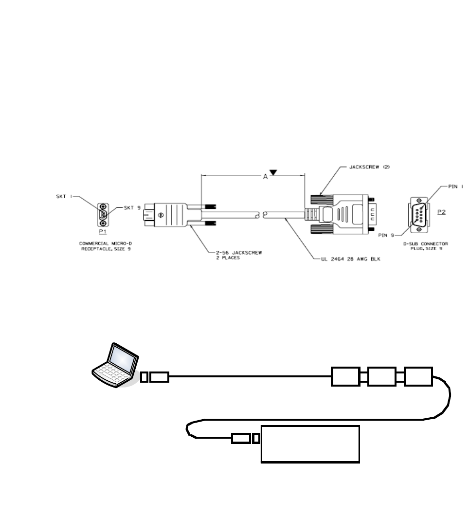
Page 4-72
User Manual
Continuous Computing Corporation
FlexPacket ATCA PP50 Packet Processor
Preliminary
4.1 Serial Console Access
4.1.1 Connect to the Serial Console
1. Construct or purchase (PN 5-02138, 72 inches) a serial the cable like the one
shown below.
The cable has a 9-pin Micro-D receptacle on one side and a standard DB-9 plug
on the other. Note a null modem cable (DB-9 receptacle on both ends) might
also be required to interface to your workstation, terminal server, laptop or USB
serial port.
Figure 4-1: Serial Console Cable
2. Connect the serial cable from a computer to the PP50’s front panel serial port.
Figure 4-2: Connecting Computer to the Serial Console
3. Run a terminal emulator program on the laptop.
USB-to-Serial Converter
Null
Modem
Micro
DB9
Serial
Connector
USB
Connector
Serial
Connector
Serial cable with Micro-DB9 connector
PP50
PC

Page 4-73
CC06786-11B
Confidential and Proprietary
Board Access, Bootup, and Shutdown
1
4ABAB
Preliminary
4. Use the following connection settings:
- 115200 baud rate
-No parity
-8 bits
-1 stop bit
- no flow control
5. Boot the PP50. By default the console is the IPMC running Linux.
6. See the next section to toggle between the IPMC and XLRs.
4.1.2 How to Switch Between Serial Consoles (IPMC, XLRs)
Use the following sequences to switch the front panel console port between CPUs:
On the front panel console, use the following sequences to connect to the XLR's
serial console via the IPMC:
• In the IPMC, use command "cu" to switch the console to XLR0
• In IPMC Linux, use command "cu" to switch the console to XLR1
• To disconnect from the XLR serial console, press “~”, and “.”.
Note: During bootup, if the board receives any keystroke signals from the serial
port, boot up will be halted. Incorrect connection settings can cause false
signals so it is critical the parameters above are set correctly.
cu -l /dev/ttyS2a
cu -l /dev/ttyS2b
cu -l /dev/ttyS2c
cu -s 38400 -l /dev/ttyS3 (secondary XLR0 console when running in dual mode Linux/
RMIOS)
cu -l /dev/ttyS4a
cu -l /dev/ttyS4b
cu -l /dev/ttyS4c
cu -s 38400 -l /dev/ttyS5 (secondary XLR1 console when running in dual mode Linux/
RMIOS)
Note: If you connect to the IPMC's console port by telnet or Windows
Hyperterm, the telnet escape character is Ctrl-].
If you use a shell or program that uses “~” as its escape character
(such as SSH or another CU session), then you must type two “~”s
for each “~” that actually needs to get to the IPMC.

Page 4-74
User Manual
Continuous Computing Corporation
FlexPacket ATCA PP50 Packet Processor
Preliminary
Note: If the hydra mode enable serial mode jumpers are installed, the XLR
console cannot be toggled. To avoid this, please make sure all jumpers on
the board are removed. See Section2.2.11, "Jumpers" for details.

Page 4-75
CC06786-11B
Confidential and Proprietary
Board Access, Bootup, and Shutdown
1
4ABAB
Preliminary
4.2 IPMC Telnet Access
The IPMC has two network interfaces. One is “eth0” for base channel A and the
other is “eth0.4094” for base channel B. By default eth0's IP address and gateway IP
address are obtained from the DHCP server. Use the ifconfig (interface configura-
tion) to obtain details.
Please see Chapter7, "Intelligent Platform Management Controller" configure eth0
and eth0.4094 via the key-value database.
4.2.1 Setting eth0 IP Address Manually
To manually set eth0's IP Address, please see the example below.
4.2.2 Setting eth0.4094 IP Address Manually
By default, eth0.4094 has no IP address. To configure its IP Address:
root@cnode-pp50:~ ifconfig
eth0 Link encap:Ethernet HWaddr 10:02:BB:50:43:44
inet addr:10.4.1.43 Bcast:10.4.255.255 Mask:255.255.0.0
UP BROADCAST RUNNING MULTICAST MTU:1400 Metric:1
RX packets:2024 errors:0 dropped:0 overruns:0 frame:0
TX packets:2 errors:0 dropped:0 overruns:0 carrier:0
collisions:0 txqueuelen:1000
RX bytes:154769 (151.1 KiB) TX bytes:1200 (1.1 KiB)
eth0.4094 Link encap:Ethernet HWaddr 10:02:BB:50:43:44
UP BROADCAST RUNNING MULTICAST MTU:1400 Metric:1
RX packets:0 errors:0 dropped:0 overruns:0 frame:0
TX packets:0 errors:0 dropped:0 overruns:0 carrier:0
collisions:0 txqueuelen:0
RX bytes:0 (0.0 B) TX bytes:0 (0.0 B)
lo Link encap:Local Loopback
inet addr:127.0.0.1 Mask:255.0.0.0
UP LOOPBACK RUNNING MTU:16436 Metric:1
RX packets:0 errors:0 dropped:0 overruns:0 frame:0
TX packets:0 errors:0 dropped:0 overruns:0 carrier:0
collisions:0 txqueuelen:0
RX bytes:0 (0.0 B) TX bytes:0 (0.0 B)
root@cnode-pp50:~ ifconfig eth0 10.4.1.43 netmask 255.255.0.0
root@cnode-pp50:~ route add default gw 10.4.0.254
root@cnode-pp50:~ ifconfig eth0.4094 192.168.0.2 netmask 255.255.255.0
root@cnode-pp50:~ route add default gw 192.168.0.254
Note: If one interface gets an IP address via DHCP, the other address is
assigned a static IP address/netmask/gateway, then there are two
default routes. When this happens the DHCP route has higher
priority.

Page 4-76
User Manual
Continuous Computing Corporation
FlexPacket ATCA PP50 Packet Processor
Preliminary
4.2.3 Setting the DNS Manually
Use vi or similar editor to manually edit the DNS configuration file shown below.
root@cnode-pp50:~ vi /etc/resolv.conf
Note: If eth0 or eth0.4094 uses DHCP protocol, it does not update the DNS
configuration. If "dnsdomain" is set to “dhcp” or null, it does not
update the DNS configuration. If “dnsdomain” is set to “disable”, it
will remove the DNS configure file (/etc/resolv.conf). If
“dnsdomain” is valid, but “dns_ns1” and “dns_ns2” are invalid, it
does not update the DNS configuration.
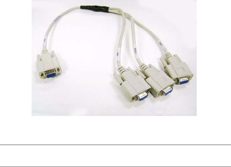
Page 4-77
CC06786-11B
Confidential and Proprietary
Board Access, Bootup, and Shutdown
1
4ABAB
Preliminary
4.3 Console Access for Development
4.3.1 Development Adapter (Hydra) Cable
To facilitate software development and debugging Continuous Computing created
a special cable which allows simultaneous console access to both XLR CPUs and the
IPMC. It is sometimes referred to as a “hydra” adapter cable and may be special
ordered from Continuous Computing(part number 0-11010). This section describes
how to use it.
This adapter cable performs the null modem function, so a null modem cable is not
used with this cable. However, users may need a straight-through serial extension
cable, with a standard DB-9 plug on one side and a DB-9 receptacle on the other,
depending on their development system configuration.
Figure 4-3: Hydra Cable for Multiple Simultaneous Connection
Note: The PP50s debug-mode jumpers must be installed (J111 and J113) to
use this cable. See Section2.2.11, "Jumpers" for details.
Page 4-78
User Manual
Continuous Computing Corporation
FlexPacket ATCA PP50 Packet Processor
Preliminary
To Connect the hydra cable:
1. Power down and remove the board if necessary and install jumpers J111 and
J112. See Section2.2.11, "Jumpers" for details.
2. Connect micro db9 to the PP50 console port.
3. Connect hydra cable to end of db9.
4. Connect one end of the hydra cable marked IPMC to either laptop or linux
machine.
5. Open serial console using hyperterminal. Set the baud rate settings as follows:
- 115200 baud rate
-No parity
-8 bits
-1 stop bit
Figure 4-4: Hydra Cable Jumpers (J111 and J113)

Page 4-79
CC06786-11B
Confidential and Proprietary
Board Access, Bootup, and Shutdown
1
4ABAB
Preliminary
4.4 Board Shutdown
PP50s can be shutdown issuing an IPMI command to deactivate the board or by
opening the front panel handle latch.
During the deactivation of the board, each of the managed FRUs on the board gets
deactivated. You can also deactivate each individual FRU by issuing deactivation
command from the Shelf Manager. For example, on Pigeon Point ShMC this com-
mand is “clia deactivate <ipmb address of board> <fru_id>”. If you deactivate the
master FRU then IPMC also deactivates all of its slave FRUs. On PP50, the Front
board FRU (id 0) is the master FRU.
During a FRU’s deactivation, all the payloads belonging to that FRU are shutdown
gracefully. Please refer to the description of KV key “shutdown_wait” in the Sec-
tion7.4.1, "KV Keys" for the configuration related to graceful payload shutdown
during FRU deactivation.
4.4.1 Using the IPMI Command to Shutdown
You can issue deactivation commands from your chassis’ shelf manager. For exam-
ple, on the Pigeon Point ShMC this command is "clia deactivate board <N>”, where
N is the logical slot number of the board. On deactivating board from shelf man-
ager, the HS (hotswap) blue led will start blinking and then become solid blue after
a while. When it is solid blue you may remove the board.
4.4.2 Using the Handle Latch to Shutdown
Leaving the board in its slot, open the board’s front handle latch out of locked posi-
tion. The blue HS (hot swap) LED will start blinking indicating the board is shutting
down. When the blue LED turns solid blue then board is shutdown and can then be
removed from the chassis slot.

Page 4-80
User Manual
Continuous Computing Corporation
FlexPacket ATCA PP50 Packet Processor
Preliminary
4.5 Board Reset
The board reset command resets all devices on the board. To reset the complete
board you can issue the IPMI Cold Reset command or reboot the CNode.
4.5.1 IPMI Cold Reset Command
In the handling of IPMI Cold Reset command (NetFn: App (0x06), Command Code:
0x02), IPMC resets complete board. On Pigeon Point ShMC, you can issue “clia
sendcmd <ipmb slave addr of board> 0x06 0x02” to send IPMI Cold Reset com-
mand to the board.
4.5.2 IPMC (CNode) Reboot
Login into the CNode and run the “reboot” command, the board will boot from
either bank 0 or bank 1.
Usually, the board boots from bank 0 or 1. If is a disturbance on the serial console
cable during the power event and reboot, the board will boot from golden bank as a
precautionary measure. The golden bank is a special bank used only for disaster
recovery. It cannot boot into the kernel.
Note: During the board reset via IPMI Cold Reset or rebooting CNode,
payloads are not shutdown gracefully. So before performing IPMI
Cold reset or rebooting CNode, user must deactivate board so that
graceful shutdown of payload takes place.
Note: If a “d” is entered in the serial console during bootup it will boot
from the golden bank image. Because it cannot the kernel a “magic
number” error message number will be output.

Page 5-81
CC06786-11B
Confidential and Proprietary
5
Preliminary
5Using the XLR SDK
To support PP50 software development you will need a build environment, which is
generally a machine running RedHat Linux with the cross-compile tool chain
installed. You will also need a machine acting as the network boot server, which can
be the same machine or an additional one.This process is described in the following
sections.
•Section5.1, "Installing RMI Source Code & Development Tools"
•Section5.2, "Installing Continuous Computing Software"
•Section5.3, "Build the Linux Kernel"
•Section5.4, "Cross Compiling Linux Applications using the RMI SDK
Crosscompiler"

Page 5-82
User Manual
Continuous Computing Corporation
FlexPacket ATCA PP50 Packet Processor
Preliminary
5.1 Installing RMI Source Code & Development Tools
To install the RMI source code and development tools, obtain the RPMs by down-
loading them from Continuous Computing’s support site. Contact your field
support engineer for the specific area and passwords. SDK version 1.6 is supported
currently.
All examples in this manual assume you install the RPMS in their default location
(/opt/rmi/x.x for the vx.x SDK). In addition, some Continuous Computing make-
files rely on a symbolic link from /devel/rmi to /opt/rmi.

Page 5-83
CC06786-11B
Confidential and Proprietary
Using the XLR SDK
1
4ABAB
Preliminary
5.2 Installing Continuous Computing Software
The Continuous Computing PP50 support package can be downloaded from Con-
tinuous Computing’s support page.
http://www.ccpu.com
The package contains the following components:
• A binary XLR bootloader with enhanced and necessary functionality for the
PP50’s flexible network connectivity.
• A pre-built Linux kernel based on RMI's kernel, with Continuous Computing
patches applied.
• A patch file that must be applied to RMI's SDK kernel source and build.
• A patch file that must be applied to RMI's SDK RMI OS
• An application for doing basic management of the PP50's onboard 10G switch.
• Binary and source code for a demonstration program that lets the two XLR
processors on the PP50 send 10GB traffic to each other.
Please refer to RMI’s XLR Programmer's Reference for information on application
development and compiling XLR applications.
http://www.netlogicmicro.com
Go to the RMI Developer Support page and create an account to download the
document.
Note: Continuous Computing's bootloader and patches must be used for
proper operation.

Page 5-84
User Manual
Continuous Computing Corporation
FlexPacket ATCA PP50 Packet Processor
Preliminary
5.3 Build the Linux Kernel
5.3.1 Apply Kernel Patches to the RMI SDK Kernel Source
1. Download the patch from Continuous’ support page at www.ccpu.com.
2. Copy src to your working directory
3. Apply the current patch file
4. Make whatever other changes you want to your working kernel tree or kernel
configuration.
5. Test them thoroughly.
5.3.1.1 Example of Using the Patch
The example below is for reference only.
5.3.2 Build the Patched Linux Kernel
Install the XLR kernel source RPM from Continuous Computing
6. Copy /opt/rmi/x.x/linux/src to a working directory (where x.x is the
version).
7. Apply the Continuous Computing patch file to your RMI Linux kernel source.
8. Set your path with the appropriate cross-compile tool chain. If you wish to
change settings in the configuration, run "make menuconfig."
cp -a /devel/rmi/1.x/linux/src /src-working
cd .../src-working
patch -p1 < pp50-linux-patch-vx.y.zr00.txt
cp -a /opt/rmi/1.x/linux/src src-1.c
cd src-1.x
patch -p1 < /raza/xlr/linux/patch-1.x/pp50-linux-patch.txt
patching file .config
patching file arch/mips/rmi/ptr/setup.c
patching file drivers/net/phoenix_mac.c
patching file drivers/net/phoenix_user_mac.c patching file include/asm-mips/rmi/
sim.h export PATH=/opt/rmi/1.x/mipscross/crosstool/gcc-3.4.3-glibc-2.3.6/
mipsisa32-xlr-linux/bin:$PATH
make menuconfig
### Make sure the options look as expected, then exit and say "yes" to using the
new configuration.
make vmlinux mipsisa32-xlr-linux-strip -o vmlinux-dbgXX vmlinux
### Kernel with debug symbols is now in vmlinux.
### Stripped kernel for netbooting or CompactFlash is now in vmlinux-dbgXX

Page 5-85
CC06786-11B
Confidential and Proprietary
Using the XLR SDK
1
4ABAB
Preliminary
9. Run "make vmlinux". This will produce a kernel with full debugging
information.
For booting through the network or CompactFlash, you will need to strip the kernel
using the cross-tool strip utility. For example, use the following script to build the
kernel:
exportPATH=$PATH:/opt/rmi/x.x/mipscross/crosstool/gcc-3.4.3-\
glibc-2.3.6/mipsisa32-xlr-linux/bin
make vmlinux
echo "Stripped kernel is named vmlinux-dbgXX"
mipsisa32-xlr-linux-strip -o vmlinux-dbgXX vmlinux

Page 5-86
User Manual
Continuous Computing Corporation
FlexPacket ATCA PP50 Packet Processor
Preliminary
5.4 Cross Compiling Linux Applications using the RMI SDK
Crosscompiler
Please refer to section 1.1, Tool Chains of the RMI SDK Manual for details on various
cross compiler options available for RMI Linux. In short, if you want to cross com-
pile a linux application on your development server, add the following line in the
makefile.
CC=/opt/rmi/1.4/mipscross/crosstool/gcc-3.4.3-glibc-2.3.6/mipsisa32-xlr-linux/
bin/mipsisa32-xlr-linux-gcc
It points to gcc cross compiler (example here is for SDK 1.4)

Page 6-87
CC06786-11B
Confidential and Proprietary
6
Preliminary
6Booting the XLRs
XLRs are booted with either Linux or an RMIOS application. Consequently, booting
procedures depend upon whether the RMIOS application or Linux is used. This
chapter summarizes those boot up methods as well as Continuous Computing’s
extension which adds flexibility and automation of to the booting procedure.
If booted with Linux, the root file system can be either in a ramdisk or a NFS server.
This chapter focuses on the boot methods (NFS or compact flash) and how to auto-
mate bootup.
This chapter only summarizes XLR boot steps. For more details please see the RMI’s
SDK documentation available from Continuous Computing or RMI on request.

Page 6-88
User Manual
Continuous Computing Corporation
FlexPacket ATCA PP50 Packet Processor
Preliminary
6.1 XLR Boot Methods
In PP50s, each of the XLR is booted independently. Essentially, XLR can be booted
via network or compact flash.
6.1.1 Network Boot
This section describes network boot methods.
6.1.1.1 Boot Server setup
Network boot involves setting up servers that will hold the software needed to boot
XLR.
Note that all the servers can be on same or different machine in network.
6.1.1.2 PP50 Setup
In order to access software (kernel, RMIOS application, file system) during boot pro-
cedure the XLR should connect to boot server(s).
Servers Reason
TFTP Needed to ftp either RMIOS application or Linux kernel.
NFS Needed from file system if Linux is booted. If Linux is run
entirely out of ramdisk, this will not be needed.
DHCP If auto configuration of IP address, mask or gateway is
desired.

Page 6-89
CC06786-11B
Confidential and Proprietary
Booting the XLRs
1
4ABAB
Preliminary
Either the PP50 front panel 1GbE, or base network 1GbE can be used for this
purpose.
6.1.1.3 Network Boot Example
To boot from a network port, use the “ifconfig” and “tftpc” bootloader commands.
An example of booting from the network on front panel 1GbE (gmac0) is shown
below. The example illustrates down loading Linux kernel and booting XLR.
Similar commands can be used to boot and run Linux kernels or RMIOS applica-
tions. Please see the RMI SDK guide for more details.
Table 6-1: Network Boot Options
Network Boot Type Recommended Appli-
cation XLR GMAC #
Front Panel 1GbE
port of XLR.
Initial lab
experimentation. Used in
deployment if boot
network needs to be
separate from the ATCA
base and fabric networks
for some reason.
GMAC0.
PP50 front panel 1GbE port for
XLR should be connected to the
network with boot server.
Network Boot from
1GbE ATCA base
network one or two.
Lab experimentation and
deployment.
GMAC2 (base channel A) and
GMAC3 (base channel B). a
a. Install a functioning ATCA switch into hub slot in your ATCA chassis. If GMAC2 is used,
switch should be present in slot that has access to base channel A. Similarly for GMAC3,
switch should have access to base channel B. Switch should be configured and connected
to the network with boot server.
Note: Ignore the initial “tftpc stall” message.
PP50-1 $ ifconfig -i gmac0 -a 172.17.69.5 -n 255.255.0.0 -g 172.17.0.254
ipaddr: 172.17.69.5
netmask: 255.255.0.0
gateway: 172.17.0.254
PP50-1 $ Starting Network interface "gmac0"
PP50-1 $ tftpc -s 172.16.0.168 -f pp50/vmlinux-pp50
Server IP : 172.16.0.168
File : pp50/vmlinux-pp50
PP50-1 $ tftpc stall, check network setup
Bytes downloaded: 9651512
tftpc: download done. size = 9651512 @ address 0x8c2ad9d0
PP50-1 $ elfload
PP50-1 $ userapp hda=noprobe

Page 6-90
User Manual
Continuous Computing Corporation
FlexPacket ATCA PP50 Packet Processor
Preliminary
6.1.2 XLR Bootloader Commands
Below is a summary of XLR bootloader commands for reference. It is RMI SDK 1.5.5
based.
PP50-1 $ help
-------------------
Available Commands:
-------------------
arp - display current arp table
autoboot - execute autoboot sequence
bk_update - erase & program the backup bootloader
boardrev - print board version number
boot_erase - erase 2MB boot section of selected flash
boot_mode_get - get boot mode
boot_update - erase & program the bootloader
bunzip2 - run bunzip2 on 'bootfile'
checksum - MD5 checksum calculator
clearenv - reset env. variables to default values
cpld_write - configure the register of cpld
cplddump - print cpld reg.values
cpldrev - print board cpld version
cpldump - print cpld reg.values
cpuinfo - prints COP-0, (I/D)-Cache and CPU# info
cpustatus - print summary of active CPUs
diag - do some diagnoses
dinfo - info on detected storage devs/controllers
dload - load file from disk into mem
dls - run 'ls' on selected storage device
elfload - validate elf file and load into mem
enable_debug - currently enables GMAC debug
env - display current env. variables
flerase - erase all or part of onboard flash chip(s)
flinfo - display onboard flash chip(s) details
flprog - program all or part of onboard flash chip(s)
fsinfo - display JFFS2-partition info
gmac_cfg - configure the gmac interface
gmac_dump_phy_regs - list GMAC PHY registers
gmac_phy_write_reg - program selected GMAC PHY registers
gphy - read & write the register of gphy
h - alias for 'help'
help - display this help menu
hist - display previous commands (max. 64)
ifconfig - bringup selected eth interface
iobus - print iodevice-subsytem mappings
kuseg_mem - display available KUSEG mem
kuseg_meminfo - available KUSEG Regions
kv - set key value
listpost - list post items
ls - display 'bootfile' info
memrd - read physical address space
memwr - write to physical address
multiboot - boot from multi device
nmiconf - configure loaded image from the NMI-mapped area
nmiload - load image to NMI mapped area
ping - ping through active eth interface
post_err - list post error codes
print_physmap - display board's phys. memory map
printenv - display current env. variables

Page 6-91
CC06786-11B
Confidential and Proprietary
Booting the XLRs
1
4ABAB
Preliminary
6.1.3 Compact Flash Boot
Each XLR in a PP50 has access to a dedicated Compact Flash (CF). Booting from a
Compact Flash eliminates the need for boot servers. To boot from a CF you must
format it and then store the necessary files (Linux kernel, RMIOS application, file
system etc) needed to boot the XLR.
If you are running Linux, you may include your application on the ramdisk if it is
small, otherwise you can put it in a live file system on the CompactFlash card or use
an NFS root.
The CompactFlash card can range from very small (16MB) to hold just an RMIOS
application image, up to very large (2GB and greater) containing redundant live
Linux file systems.
psb_info - display contents of global 'psb_info' struct
reboot - reboot the board
reg - read & write the register
regrd - display Reg. Values from IOBASE
regwr - change IOBASE Reg. Values
rollboot - switch flash bank and reboot
run - load elf file, call command 'userapp'
saveenv - save env. variables into non-volatile mem
savenv - save env. variables into non-volatile mem
setenv - assign value to env. variable
showboot - show flash bank
stop_vcpu - stop running selected vCPU
tftpc - start tftp client
tlbinfo - identify current, print all 16 TLB info
userapp - launch kseg0 application on XLR0
userapp_mask_cpus - set active-cpu bitmask
userapp_noreset - do not reset msgring0/gmac0 for 'userapp'
userapp_os - launch kuseg application(s)
version - print bootloader version info
xgm - read & write the xgm interface
xgphy - read & write the register of xphy
xlr_reserve_mem - reserve a block of physical memory
PP50-1 $

Page 6-92
User Manual
Continuous Computing Corporation
FlexPacket ATCA PP50 Packet Processor
Preliminary
6.1.3.1 Formatting Compact Flash
A CF card may use either FAT or EXT2 file system. This section provides one exam-
ple of formatting CF from linux in XLR.
1. Boot Linux in XLR.
2. Zero out the CF to ensure its integrity.
3. Format the CF and mount it.
4. The relevant files can be copied to CF.
6.1.3.2 Booting from Compact Flash
RMI SDK provide details of the boot command used to boot Linux or RMIOS from
Compact Flash. This section summaries the instructions to boot Linux from Com-
pact Flash (CF) card.
1. Copy the Linux kernel file (for example, vmlinux-p2-dbg03) to the CF card.
Root file system, if needed, should also be copied in CF.
2. Insert the CF card into pp50 p2 board and bootup.
3. Get disk and partition information.
According to above, the disk name is pcmcia_1, the partition the number is 1.
ifconfig -i gmac2 -a 192.168.200.200 -g 192.168.70.1 -n 255.255.0.0
tftpc -s 192.168.70.20 -f pp50-linux-kernel-vX.X.Xb00
elfload
userapp ip=192.168.200.200:192.168.70.20:192.168.70.1:255.255.0.0::eth2:off
console=ttyS0,38400
dd if=/dev/zero of=/dev/hda bs=512 count=1
fdisk /dev/hda
<fdisk is interactive so these are entered sequentially>
n, p, 1, enter, enter, p, w
mkfs /dev/hda1
mkdir /cf
mount /dev/hda1 /cf
PP50-0 $ dinfo print
List of IDE disks found:
Disk: pcmcia_1 Controller: pcmcia
=======================================
Model: LEXAR ATA FLASH
Firmware: V1.00 Serial#: 11014182459999090004
Capacity: 983.8 MB = 0.9 GB (2014992 x 512)
Partition Table.
-----------------
1 63 2014929 b
PP50-0 $

Page 6-93
CC06786-11B
Confidential and Proprietary
Booting the XLRs
1
4ABAB
Preliminary
4. List CF card operation commands
5. List the CF card files
6. Load file vmlinux-p2-dbg03 to memory.
If the CF is formatted to FAT run:
If the CF is formatted to ext run:
7. Load the elf file
8. Boot RMI Linux
PP50-1 $ dls
Filesystem Commands
dload <disk> <partition> <file> [bytes] - Load the specified number of [bytes]
from <disk> <partition> <file> to memory.
If [bytes] is omitted, then the value of bytes will be the size of file or 15MB,
whichever is less.
dls <disk> <partition> [directory] - list the files from <disk> <partition> [dir]
PP50-1 $
PP50-1 $ dls pcmcia_1 1
Listing / directory.
0 thisiscompactflash
3139 testcmd.txt
9684280 vmlinux-p2-dbg03
3910938 vmlinux-wr05
4 file(s), 0 dir(s)
PP50-1 $
PP50-1 $ dload pcmcia_1 1 vmlinux-p2-dbg03
PP50-1 $ dload pcmcia_1 1 /vmlinux-p2-dbg03
PP50-1 $ elfload
PP50-1 $userapp hda=noprobe hdb=noprobe

Page 6-94
User Manual
Continuous Computing Corporation
FlexPacket ATCA PP50 Packet Processor
Preliminary
6.2 Automating XLR boot
Booting the XLR, either from a network or compact flash, requires users to execute a
set of commands from XLR bootloader prompt. This section describes the two meth-
ods of automating execution of those commands: Section6.2.1, "Continuous
Computing Multiboot" and Section6.2.2, "Autobooting Using Environment
Variables".
Following are two methods to automate the execution of boot commands. Continu-
ous Computing multiboot is a more comprehensive feature that ties XLR boot to the
overall management of PP50 board in a chassis.
6.2.1 Continuous Computing Multiboot
Continuous Computing’s Multiboot provides several useful features for booting
XLRs:
• Allows specification of multiple boot methods (network with or without
DHCP, compact flash) and their relative preferences.
• Allows control of the XLR boot sequence though IPMI. This is important
because it no longer requires access to the XLR bootloader to modify the boot
sequence.
• Provides a mechanism to recover from failed boot attempts.
6.2.1.1 Key Values (KV)
Key values are environment variables set in the IPMC to be accessed by the XLR
bootloader. The Multiboot feature is implement by the user setting up the KV vari-
ables needed for XLR boot in IPMC. Every time bootloader starts, it will read
relevant variables and perform required functionality. Following are the list of KV
variable needed for multiboot, following section will detail syntax and semantics for
each on the set.
KV Variable Note
sX_bootXdevX Specific the boot device. Examples include network with
dhcp, network without dhcp, compact flash.
sX_bootXfileX bootfile name. Examples are Linux kernel, rmios
application.
sX_bootXcmd Command to boot image. Examples are “elfload” and
“userapp” to boot Linux image or rmios application.
sX_bootXargsX Arguments to boot command, if any. Example are
“hda=noprobe” for Linux boot.

Page 6-95
CC06786-11B
Confidential and Proprietary
Booting the XLRs
1
4ABAB
Preliminary
6.2.1.2 KV Variable Syntax
The complete name of KV variable in above table is derived by replacing the “X”
with appropriate values as defined here.
CPU name
There are separate KV variable for XLR0 and XLR1. The XLR0 variables start with
s0_* and XLR1 variables with s1_*
Boot method
As explained in next section, users can specify maximum of 4 boot methods to be
used in sequence (if last one failed) to bring up XLR. The second “X” in KV name
represents the boot method. For example, in XLR0 the set of variable that control
first boot method are s0_boot0devX, s0_boot0fileX, s0_boot0cmd, s0_boot0argsX.
Size Limitation
Each of KV variable is a string. The maximum size of string is limited to 32 charac-
ters. Last “X” in the KV variable name is used add more KV variable to represent a
string > 32 characters. Please note that sX_bootXcmd does not have this extension
feature, all boot commands must fit into 32 characters.
Example
To set XLR0’s first boot method to be “network with static IP” use the command:
PP50-0 $ kv s0_boot0dev0 “gmac0:10.4.69.10:255.255.0.0:”
PP50-0 $ kv s0_boot0dev1 “10.4.0.254;end”
For the boot device variable, there can be a maximum of 2 extensions. This means
that the range of last X is {0 . . 1}.
Similarly for boot file variable, there can be 4 extensions and for the boot arguments
variable there can be 8 extensions.
All characters in KV variables are case sensitive.
Note: The end of string is indicated by the flag string “;end”.
Note: Even if the string is less than 32 characters, user should still use
s0_boot0dev0 variable and add “;end” in the end.\

Page 6-96
User Manual
Continuous Computing Corporation
FlexPacket ATCA PP50 Packet Processor
Preliminary
6.2.1.3 Access to Multiple Boot Method
The multiboot method allows users to specify multiple boot methods to be tried in a
given sequence. For example, the user can set “network with dhcp” as the first
option to boot XLR, “network with static IP” as second option in case DHCP server
is down and so on. The bootloader will start with first method, if it fails to bring up
the board it will try the next method and so on. The user can specify up to four such
boot methods.
The bootloader decides a boot method has failed based on the watchdog mechanism
explained in Section6.2.1.8, "Watchdog Feature". If the watchdog timer expires, it
will use the next boot method in sequence.
6.2.1.4 Boot Method Syntax
Following table lists the syntax of KV variable sX_bootXdevX that specifies the boot
method.
Since colon(':') is used in the syntax of string, it can't be used in directory or file
name.
For example, network boot using gmac2 and DHCP for second boot method in
XLR1.
Syntax Boot Source Note
gmacN:IP[:mask][:gat
eway]
(static IP) Select the boot GMAC port and specify
the static host IP address to be used.
gmacN:dhcp_only (dynamic IP) Host IP address is requested from
DHCP server.
gmacN:dhcp_tftp (dynamic IP) Host IP address, gateway, TFTP server
and boot file name are requested from
DHCP server.
Note that in this case user does not
have to specify sX_bootXfileX variable.
cflash:partition (CF card boot) CF card as boot device, the partition
field is the partition number.
PP50-1 $ kv s1_boot1dev0 “gmac2:dhcp_only;end”

Page 6-97
CC06786-11B
Confidential and Proprietary
Booting the XLRs
1
4ABAB
Preliminary
Following are other examples strings for static IP allocation.
• gmacN:IP;end (no mask, no gateway)
• gmacN:IP:mask;end (with mask, no gateway)
• gmacN:IP: :gw;end (no mask, with gateway, note: one space must be added
between “IP” and “gw”)
• gmacN:IP:mask:gw;end (with mask, with gateway)
6.2.1.5 Specifying Boot file
Next KV variable after boot method is path/name of the boot file. In case of network
boot method, the path of file is prefixed with IP address of the boot server that holds
the boot file and runs TFTP server. The boot files usually are Linux kernel image or
RMIOS application image.
6.2.1.5.0.1 Syntax of Boot File
The following table lists the syntax of KV variable sX_bootXfileX that specifies the
boot file.
Following example shows setting up pp50/images/pp50-linux-kernel-v2.2.3b01 file
as boot file in XLR0, boot method 1 using network boot.
Setting up pp50/images/pp50-linux-kernel-v2.2.3b01 file as boot file in XLR0, boot
method 4 using compact flash.
6.2.1.6 Specifying Boot command
Next KV variable after boot file is the boot command string. Please refer to RMI SDK
for syntax and semantics of boot command. Essentially boot command string con-
sists of XLR bootloader commands to load and boot the XLR.
6.2.1.6.0.2 Syntax of Boot command
The KV variable used for boot command is sX_bootXcmd.
Syntax Boot Method Note
<tftp server>:<file> network IP of TFTP server and boot file name in
the server.
<file> compact flash boot file name in compact flash.
PP50-0 $ kv s0_boot0file0 "10.4.69.69:pp50/images/"
PP50-0 $ kv s0_boot0file1 "pp50-linux-kernel-v2.2.3b01;end"
PP50-0 $ kv s0_boot3file0 "pp50/images/"
PP50-0 $ kv s0_boot3file1 "pp50-linux-kernel-v2.2.3b01;end"

Page 6-98
User Manual
Continuous Computing Corporation
FlexPacket ATCA PP50 Packet Processor
Preliminary
Boot command to boot a Linux or RMIOS KUSEG image.
Notice the absence of last “X” in KV variable and the absence of “;end” string in the
end. One key should be enough for the bootcmd argument in any kind of logical
boot device. Multiple boot commands can be combined with semicolon (";") as list
separator.
6.2.1.7 Specifying Boot Arguments
Next KV variable after boot command is the boot command arguments. Please refer
to RMI SDK for syntax and semantics of boot command arguments.
6.2.1.7.1 Boot Argument Syntax
The following example sets the KV boot argument variables as shown in the table
below it:
"hda=noprobe hdb=noprobe root=/dev/nfs nfsroot=10.3.8.23:/rmi/1.4/nfsroot
ip=10.4.69.11:10.3.8.23:10.4.0.254:255.255.0.0::eth2:off console=ttyS0,38400"
6.2.1.8 Watchdog Feature
Users can specify four four methods of booting: regular boot, boot file, boot com-
mand, and boot args in a sequence as part of Continuous Computing’s multiboot.
XLR bootloader will start with last tried boot sequence and, if it fails to boot XLR, it
will continue with next method in sequence.
The decision as to when a boot sequence is considered to have “failed” to bring up
the XLR is based on the watchdog timer. The following are important points to con-
sider regarding the watchdog timer.
• At the start of each boot sequence, XLR bootloader will tell the IPMC to start
watchdog timer. The value of watchdog timer is controlled by KV variable
sX_bootwd.
• If the timer times out, IPMC will consider boot sequence as failure as will
reboot XLR. Once the reboot is finished the XLR will continue with next boot
method in sequence.
PP50-0 $ kv s0_boot0cmd "elfload;userapp"
PP50-0 $ kv s0_boot0args0 "hda=noprobe hdb=noprobe "
PP50-0 $ kv s0_boot0args1 "root=/dev/nfs nfsroot="
PP50-0 $ kv s0_boot0args2 "10.3.8.23:/rmi/1.4/nfsroot "
PP50-0 $ kv s0_boot0args3 "ip=10.4.69.11:10.3.8.23:"
PP50-0 $ kv s0_boot0args4 "10.4.0.254:255.255.0.0::eth2:"
PP50-0 $ kv s0_boot0args5 "off console=ttyS0,38400;end"

Page 6-99
CC06786-11B
Confidential and Proprietary
Booting the XLRs
1
4ABAB
Preliminary
• If the boot method is successful, it is the responsibility of booted entity to stop
the watchdog timer in IPMC. Failure to do so will result in IPMC rebooting
XLR. Currently, if XLR is booted to Linux, user can add a utility called
“ipmi_setwd” as part of their root file system. Calling this utility, preferably
from init scripts, will reset the watchdog timer in IPMC. Currently, there is no
such utility available for RMIOS application.
• The watchdog feature can be disabled by setting value of sX_bootwd to 0. In
this case user have to manually reboot XLR to continue with next boot
sequence.
It is important to set the right value for watchdog timer. The value should ideally be
largest of the time it take to boot XLR for each sequence. Given that booting Linux
takes most time, the timer value can be set based of Linux boot time. Typically it
takes about 60 seconds to boot the RMI Linux or WindRiver Linux kernel on PP50,
so 70 is a good value to start with.
Example of setting watchdog timer.
To find which payload stage's watchdog timer expired run the following command:
6.2.1.8.2 Stopping Watchdog Timer in Linux
As noted above after a successful boot, the watchdog timer must be stopped. Linux
provides the “ipmi_setwd” utility which can perform this operation (present in Util-
ities directory in release).
For booting RMI linux kernel from its own RAM FS
• The binary of RMI Linux kernel with version later than "v2.2.3b00" has included
this utility as part of ramdisk.
• For kernel version less that "v2.2.3b00" user has to rebuild kernel and add this
utility as part of initramfs.
For booting linux from nfsroot you need to add “ipmi_setwd” in /usr/bin of the
nfsroot and set it as executable using the "chmod a+x ipmi_setwd" command.
You must also add following line in the nfsroot script file /etc/inittab,
6.2.1.9 Initializing Multiboot
Multiboot is initialized by setting kv entries as described below.
6.2.1.9.3 Setting the s[0_1]_multiboot Key Value
Specify the way of XLR multiboot/autoboot through setting the s[0|1]_multiboot
KV key.
PP50-0 $ kv s0_bootwd "70"
cat /var/log/messages | grep expired
0:12345:once:/usr/bin/ipmi_setwd 0

Page 6-100
User Manual
Continuous Computing Corporation
FlexPacket ATCA PP50 Packet Processor
Preliminary
KV key s[0|1]_multiboot =
1 - Try to boot from KV key boot0dev (similar to "multiboot -s 0")
2 - Try to boot from KV key boot1dev (similar to "multiboot -s 1")
3 - Try to boot from KV key boot2dev (similar to "multiboot -s 2")
4 - Try to boot from KV key boot3dev (similar to "multiboot -s 3")
5 - Try to boot from KV keys boot0dev through boot3dev (similar to "multiboot -s
a")
10 - Try to boot using the XLR's environment variables - bootcmd0 through
bootcmd9
20 - Do not auto boot, force to bootloader prompt regardless of environment vari-
ables and Key-Value settings
Unsupported value - Display this usage information and force to bootloader prompt
6.2.1.9.3.1 Setting the s[0|1]_bootdelay Key Value
Specify the waiting time before starting multiboot/autoboot through setting the KV
key s[0|1]_bootdelay.
s[0|1]_bootdelay = 0 - boot with no waiting
< 0 - do not boot and force to bootloader prompt
> 0 - start to boot after the set time (seconds)
Note: If KV key s[0|1]_multiboot is not set or deleted, XLR will auto boot
using the environment variables (bootdelay, bootcmd0 through
bootcmd9), which is as same as chapter 6.2.2 said.
Note: If the kv key s[0|1]_bootdelay is not set or deleted, it will be
handled as if the default value '-1' was set and will force the
bootloader prompt.
Note: If the kv key s[0|1]_bootdelay is set to a wrong value by mistake, it
will boot with no waiting.

Page 6-101
CC06786-11B
Confidential and Proprietary
Booting the XLRs
1
4ABAB
Preliminary
6.2.1.10 Multiboot Example
The following examples show three boot sequences for XLR0.
Initialize multiboot feature
Sequence 1: Multiboot using GMAC0 and static IP
Sequence 2: Multiboot using GMAC0 and DHCP and TFTP option
Sequence 3: Multiboot Using GMAC0 and DHCP for IP address
6.2.2 Autobooting Using Environment Variables
User can also use RMI “bootcmd” environment variables to specify a sequence of
commands to be executed by bootloader. Note that this method of automating XLR
boot sequence is not as comprehensive as Continuous Computing autoboot feature.
It requires users access to XLR bootloader and does not provide flexibility to try
multiple boot methods in sequence. Please refer to RMI SDK for more details on this
feature.
kv s0_bootmode "normal"
kv s0_bootwd 70
kv s0_multiboot 5
kv s0_bootdelay 3
kv s0_boot0dev0 "gmac0:10.4.2.2:255.255.0.0;end"
kv s0_boot0file0 "10.4.3.69:pp50-linux-kernel"
kv s0_boot0file1 "-v2.2.3b00/"
kv s0_boot0file2 "pp50-linux-kernel-v2.2.3b00"
kv s0_boot0file3 ";end"
kv s0_boot0cmd "elfload;userapp"
kv s0_boot1dev0 "gmac0:dhcp_tftp;end"
kv s0_boot1cmd "elfload;userapp"
kv s0_boot2dev0 "gmac0:dhcp_only;end"
kv s0_boot2file0 "10.4.3.69:pp50-linux-kernel"
kv s0_boot2file1 "-v2.2.3b00/"
kv s0_boot2file2 "pp50-linux-kernel-v2.2.3b00"
kv s0_boot2file3 ";end"
kv s0_boot2cmd "elfload;userapp"
PP50-0 $ reboot

Page 6-102
User Manual
Continuous Computing Corporation
FlexPacket ATCA PP50 Packet Processor
Preliminary
6.3 XLR Utility
Continuous Computing has added a set of commands to simplify Linux booting
and management procedures. Some are available from the bootloader before Linux
runs: Section6.3.2, "XLR Commands Available From the BootLoader", others are
available after Linux runs; Section6.3.3, "XLR Commands Available From Linux".
6.3.1 Installing Linux Utilities
These utilities are in the release package’s in “Utilities” directory. They are already
part of ramfs, but if nfsroot is used the following steps must be performed to get
these utilities in nfsroot.
6.3.1.1 RMI Linux
1. Get the NFS package from RMI SDK and unpack it.
2. Copy the files to the NFS root.
3. Utilities directory to bin directory in nfsroot.
4. Create link for net_config
6.3.1.2 WR Linux
The script and relative utilities have been integrated into the BSP for Wind River
PNE Linux, but for additional changes, please refer to the Section9.3, "Building the
Kernel and NFS" for more information.
root # mkdir Utilities
root # tar -xzvf pp50-xlr-utils-vx.x.xr00.tgz -C Utilities
root # cp Utilites/kv <NFS dir>/bin/
root # cp Utilites/getcpuid <NFS dir>/bin/
root # cp Utilities/net_config <NFS dir>/etc/rc.d/init.d/
root# cd <NFS dir>/etc/rc.d/rc2.d/
root# ln –s ../init.d/net_config S31net_config
root# cd <NFS dir>/etc/rc.d/rc3.d/
root# ln –s ../init.d/net_config S31net_config
root# cd <NFS dir>/etc/rc.d/rc4.d/
root# ln –s ../init.d/net_config S31net_config
root# cd <NFS dir>/etc/rc.d/rc5.d/
root# ln –s ../init.d/net_config S31net_config

Page 6-103
CC06786-11B
Confidential and Proprietary
Booting the XLRs
1
4ABAB
Preliminary
6.3.2 XLR Commands Available From the BootLoader
The commands in this section are included in the XLR and IPMC firmware and are
used to boot the XLR.
6.3.2.1 kv
Sets a key value in the database. See Section7.4, "Key Value (KV) Database" for
details.
Detail Description
Synopsis kv [key [value]]
Options -k prints entries in shell-compatible syntax.
-V display version of kv utility.
-h display command usage.
-d delete a key from database.
Examples xlr prompt] kv
ipmc_version = "pp50-ipmc-v2.4.3r00"
datetime = "2009-04-29 23:20:42"
epochtime = "1241047243"
xlr0base = "00:02:BB:50:32:90"
xlr1base = "00:02:BB:50:32:98"
pyld0_compat = "8.2"
pyld1_compat = "8.2"
hwaddr = "43"
f1_presence = "1"
f2_presence = "0"
__pwr_regs = "ff00000000000000"
__f0_poh = "770"
__s0_rstcause = "cold_reset"
__s0_rsttime = "2009-04-29 23:07:31"
__s1_rstcause = "cold_reset"
[xlr prompt] kv -V
kv version 1.1
[xlr prompt] kv hello there
[xlr prompt] kv hello
hello = "there"
[xlr prompt] kv -d hello
[xlr prompt] kv hello
Key 'hello' not found

Page 6-104
User Manual
Continuous Computing Corporation
FlexPacket ATCA PP50 Packet Processor
Preliminary
6.3.2.2 showboot
Shows the bank where the bootloader booted from (xlr active flash bank id).
6.3.2.3 rollboot
Switches to the other flash bank and boots.
6.3.3 XLR Commands Available From Linux
The following commands are available after the XLR has booted WR/RMI Linux.
6.3.3.1 NTP client
The Network Time Protocol (NTP) daemon synchronizes RMI Linux time with NTP
servers. Please refer to README file in NTP directory of Utilities package for more
on installation.
6.3.3.2 kv
See Section6.3.2.1, "kv" for details.
6.3.3.3 showboot
See Section6.3.2.2, "showboot" for details.
Detail Description
Synopsis showboot
Options no options
Examples [xlr prompt] showboot
System was booted from bank 0.
The active bank version is: v2.5.0r00
Detail Description
Synopsis rollboot
Options none
Example [xlr prompt] rollboot
System was booted from bank 0.
The active bank version is: v2.5.0r00
Rollboot to bank 1...

Page 6-105
CC06786-11B
Confidential and Proprietary
Booting the XLRs
1
4ABAB
Preliminary
6.3.3.4 rollboot
See Section6.3.2.3, "rollboot" for details.
6.3.3.5 ipmi_setwd
IPMI Set WatchDog timer, reboots the XLR based on the time specified; supports
XLR multiboot feature. For details about its usage also see Section6.2.1.8, "Watch-
dog Feature".
6.3.3.6 fswcmd
Fabric Switch Command, provides fabric switch operation from the XLR side. See
Section8.2.1, "Managing the Fabric Switch with fswcmd" for details.
6.3.3.6.1 fswcmd.cfg Configuration File
A small configuration file named fswcmd.cfg included in the release package pro-
vides the address for the IPMC to ensure it can be accessed; for example, if the
accessible IPMC interface IP address is 10.4.1.10, the following line should be in the
fswcmd.cfg
This config file indicates where the fabric switch daemon 'fswd' is. This file is
required only when the fswcmd is executed on the XLR (RMI Linux or WindRiver
Linux).
Note this is not be confused with the fswitchCfg.def file and its associated kv key
fswitchCfg. See Section8.2, "Fabric Switch Management" and Section8.2.2, "fswcmd
Start Up File" for more details.
Detail Description
Synopsis ipmi_setwd [-hv][seconds]
Options -h help
-v display version
seconds(decimal) = 0 stops the watchdog timer
seconds(decimal) > 0 starts the watchdog timer
Examples [xlr prompt] ipmi_setwd 22
ip_address 10.4.1.10

Page 6-106
User Manual
Continuous Computing Corporation
FlexPacket ATCA PP50 Packet Processor
Preliminary
6.3.3.7 upgrade
For upgrading the xlr flash bank
6.3.3.8 bswcmd
The bswcmd command provides base switch operation and information. See Sec-
tion8.6, "CNode Base Switch (bswcmd) Command" for more information about this
command.
6.3.3.9 getcpuid
Returns the XLR CPU ID of the XLR you are currently using.
Detail Description
Synopsis upgrade <-a | -s> [options]
Options ? Display this usage
-V Display version of this program
-a Use active flash for operation
-s Use backup flash for operation
-b <backup file> Backup flash info to a file
-p <program file> Program file to flash
-v <program file> Verify flash info with a file
Examples To backup:
[xlr prompt] ./upgrade -a -b bootloader.bck
To program:
[xlr prompt] ./upgrade -s -p bootloader.bin
To verify:
[xlr prompt] ./upgrade -s -v bootloader.bin
Detail Description
Synopsis getcpuid
Options None
Examples [root@localhost xlr-utils]$ ./getcpuid
xlr cpu id is: 0

Page 6-107
CC06786-11B
Confidential and Proprietary
Booting the XLRs
1
4ABAB
Preliminary
6.3.3.10 net_config
Configures the network interface using the KV keys in the database. It replaces
setkv.
6.3.3.11 ipmi_setwd
Sets watchdog for supporting the XLR multiboot feature.
Usage: ipmi_setwd [-hv][seconds]
where:
-h help
-v display version
seconds(decimal) = 0 stops the watchdog timer
seconds(decimal) > 0 starts the watchdog timer
Detail Description
Synopsis net_config {start|stop|restart|reload|status}
Options {start|stop|restart|reload|status}
Examples [xlr prompt] ./net_config stop
[xlr prompt] ./net_config restart
[xlr prompt] ./net_config reload
[xlr prompt] ./net_config start
Auto configure network from kv database... [ OK ]
[xlr prompt] ./net_config status

Page 6-108
User Manual
Continuous Computing Corporation
FlexPacket ATCA PP50 Packet Processor
Preliminary
6.3.3.12 ux_diag
Diagnostic management utility based on kv schema.
Usage:
[Linux Prompt]$ ./ux_diag -h
usage: ux_diag [-u|--update] [cn|s0|s1]
usage: ux_diag [-l|--list] [cn|s0|s1]
usage: ux_diag [-d|--dump] [cn|s0|s1]
usage: ux_diag [-n|--no] [cn|s0|s1]
usage: ux_diag [-h]
-u update diagnosis configuration using /etc/diag/XX_diag.cfg
-l list all available test items and test states configuration
-d dump the test result and create /var/log/XX_diag.dump
-n list current diagnosis test error number and err string
-h for help

Page 7-109
CC06786-11B
Confidential and Proprietary
7
Preliminary
7Intelligent Platform Management
Controller
This chapter describes the Intelligent Platform Management Controller (IPMC) on
the PP50. The PP50 implements IPMC module on a Linux based system using a
PPC405EZ processor. This processor is referred to as the CNode. Apart from the
IPMC module, the CNode also runs various other modules to control the base and
fabric switches on a PP50. This chapter concentrates on the IPMC module.
The IPMC module is a single threaded, user level daemon process (ipmcd) running
on the CNode. This daemon process is started using one of the startup scripts on
Linux.
Following are the main functions of the IPMC module:
• Provides an interface to Shelf Manager over IPMB channel for the management
of the blade as per PICMG 3.0 Revision 2.0 AdvancedTCA Base Specification
and IPMI v1.5 specification.
• Provides an interface to the payload CPUs over the SIPL channel.
• Provides an interface to the System Manager using RMCP over base interface
ethernet.
• Provides an interface to switch management applications for E-Keying.

Page 7-110
User Manual
Continuous Computing Corporation
FlexPacket ATCA PP50 Packet Processor
Preliminary
7.1 FRU Support
The PP50 IPMC provides two managed FRUs:
• Front Board (FRU # 0)
•RTM (FRU # 1)
There is also one unmanaged FRU, the TCAM (FRU # 2).
The front board FRU acts as the master FRU, meaning other FRUs cannot be made
active unless front board FRU is active. Similarly, if the front board FRU is deacti-
vated then other slave FRUs are automatically deactivated.
Managed FRUs are visible to the shelf manger (and system manager) for all the
management purposes including its activation and deactivation. Unmanaged FRUs
are activated and deactivated by the front board FRU itself during the master FRU’s
activation and deactivation.
Optionally, the IPMC also provides the flexibility to create one managed FRU for
each of the XLRs using the KV key "xlrfru". Please refer to Table 7-5 "Key Value
Database" for description of KV key "xlrfru". By default, IPMC does not create a
managed FRU for XLRs and rather each of the XLRs are payloads of Front Board
FRU only. When a managed FRU for each of the XLRs are created, the IPMC creates
the following additional FRUs:
• FRU # 3 for PP50-P2 XLR0
• FRU # 4 for PP50-P2 XLR1
Even though, the IPMC creates a managed FRU for each XLR, the XLRs are not
actual field replaceable unit and so having a managed FRU for them is purely for
management purposes only. For the same reason, the IPMC does not create and
maintain any separate FRU data for XLR FRUs and so "Read FRU Data" commands
for XLR FRU returns FRU data of Front Board FRU only and "Write FRU Data" com-
mand is not applicable for XLR FRUs.
7.1.1 FRU State
PICMG 3.0 defines a standard FRU state machine to allow controlled introduction
and removal of hardware to and from a running system. All the managed FRUs on
the PP50 follow the state machine defined by PICMG specifications. Managed FRUs
require a management activation from shelf (and/or system) management; they do
not become active without an interaction with shelf (and/or system) management
application.
Note: When installing and removing RTMs, ensure they are securely
attached to the chassis by tightening the thumb bolts. Failure to do
so may result in improper board behavior.

Page 7-111
CC06786-11B
Confidential and Proprietary
Intelligent Platform Management Controller
1
4ABAB
Preliminary
Managed FRU’s state machine is affected by events from shelf (and/or system)
management, ejector latches, hardware presence detection, and other timers or
behaviors internal to the IPMC.
7.1.2 FRU Hot swap Sensors
For each managed FRU, the PP50 provides a FRU Hotswap Sensor as defined by the
ATCA specification to indicate FRU state (M0-M7). Hotswap sensor can be enabled
to provide notification via sensor events any time the hot swap state of that FRU
changes.
For unmanaged FRU (TCAM), PP50 provides a Presence Sensor which can be que-
ried to detect presence of the FRU.
See Section7.2, "Sensors" for details on all the sensor supported by the PP50.
7.1.3 FRU Data
FRU inventory data is usually accessed through the shelf manager, or remotely
using HPI (Hardware Platform Interface).
The PP50 allows frudata read and write for both managed and unmanaged FRUs.
Below is an example of obtaining FRU data on a 5U chassis with a Pigeon Point-
ShMC. It is an example only, your method of access and data will vary based on
your shelf management and system management interface.
7.1.3.1 Example of FRU Data using Pigeon Point ShMc
In this example, the PP50 board is seated in slot 3 (IPMB address of 0x86) on Schroff
5U chassis. The command to read FRU data of front board is:
where:
• 86 is the IPMB address of the PP50 board and will vary depending on which
slot the board occupies.
Note: There is no guaranteed association between sensor numbers and
FRU numbers. Therefore users are advised not to put specific sensor
numbers into their management applications. Instead, the
management application should rely on sensor event messages
which include the FRU number as a data field, or it can read and
search the sensor data records using the sensor name to look up the
sensor number at run time if needed.
fruinfo 86 0

Page 7-112
User Manual
Continuous Computing Corporation
FlexPacket ATCA PP50 Packet Processor
Preliminary
• 0 is the logical FRU number for the PP50 Front board FRU.
Command to read FRU data for PP50 RTM FRU is:
where:
• 86 is the IPMB address of the PP50 board and will vary depending on which
slot the board occupies
• 1 is the logical FRU number for the PP50 RTM FRU
CLI> fruinfo 86 0
86: FRU # 0, FRU Info
Common Header: Format Version = 1
Internal Use Area:
Version = 1
Board Info Area:
Version = 1
Language Code = 25
Mfg Date/Time = Aug 8 02:44:00 2007 (6101444 minutes since 1996)
Board Manufacturer = Continuous Computing Corp.
Board Product Name = FlexPacket ATCA-PP50
Board Serial Number = 00:02:bb:50:02:00
Board Part Number = 0-XXXXX-NN
FRU Programmer File ID =
Product Info Area:
Version = 1
Language Code = 25
Manufacturer Name = Continuous Computing Corp.
Product Name = FlexPacket ATCA-PP50
Product Part / Model# = PP50 0-9XXXX
Product Version = X00 P2
Product Serial Number = CT7-00578
Asset Tag =
FRU Programmer File ID =
Multi Record Area:
PICMG Board Point-to-Point Connectivity Record (ID=0x14)
Version = 0
CLI>
fruinfo 86 1
CLI> fruinfo 86 1
86: FRU # 1, FRU Info
Common Header: Format Version = 1
Internal Use Area:
Version = 1
Board Info Area:
Version = 1
Language Code = 25
Mfg Date/Time = Aug 8 02:44:00 2007 (6101444 minutes since 1996)
Board Manufacturer = Continuous Computing Corp.
Board Product Name = FlexPacket ATCA-PP50 RTM
Board Serial Number = CZ8-11539
Board Part Number = 0-11024-E06

Page 7-113
CC06786-11B
Confidential and Proprietary
Intelligent Platform Management Controller
1
4ABAB
Preliminary
The command to read FRU data for PP50 TCAM FRU is:
where:
• 86 is the IPMB address of the PP50 board and will vary depending on which
slot the board occupies
• 2 is the logical FRU number for the PP50 TCAM FRU (unmanaged FRU)
FRU Programmer File ID =
Product Info Area:
Version = 1
Language Code = 25
Manufacturer Name = Continuous Computing Corp.
Product Name = FlexPacket ATCA-PP50 RTM
Product Part / Model# = PP50 0-9XXXX
Product Version = X00 P2
Product Serial Number = CZ8-11539
Asset Tag =
FRU Programmer File ID =
CLI>
fruinfo 86 2
CLI> fruinfo 86 2
86: FRU # 2, FRU Info
Common Header: Format Version = 1
Internal Use Area:
Version = 1
Board Info Area:
Version = 1
Language Code = 25
Mfg Date/Time = Aug 8 02:44:00 2007 (6101444 minutes since 1996)
Board Manufacturer = Continuous Computing Corp.
Board Product Name = FlexPacket ATCA-PP50 TCAM
Board Serial Number = CZ8-19683
Board Part Number = 0-11761-E03
FRU Programmer File ID =
Product Info Area:
Version = 1
Language Code = 25
Manufacturer Name = Continuous Computing Corp.
Product Name = FlexPacket ATCA-PP50 TCAM
Product Part / Model# = PP50 0-9XXXX
Product Version = X00 P2
Product Serial Number = CZ8-19683
Asset Tag =
FRU Programmer File ID =
CLI>

Page 7-114
User Manual
Continuous Computing Corporation
FlexPacket ATCA PP50 Packet Processor
Preliminary
7.2 Sensors
This section describes the PP50’s sensors. The following table lists all the sensors
available on PP50. Please refer to IPMI specification for details on sensor type, sen-
sor class and sensor event/reading type codes.
Table 7-1: PP50 Sensor List
Sensor Name Sensor
Type Sensor
Class Event/Read-
ing Type Code Sensor Descrip-
tion
Front Hotswap Hot Swap Discrete Sensor Specific
(0x6f)
FRU Hot Swap
Sensor
RTM Hotswap Hot Swap Discrete Sensor Specific
(0x6f)
'FRU Hot Swap
Sensor'
IPMB Physical IPMB Link Discrete Sensor Specific
(0x6f)
Physical IPMB-0
Sensors
-48V A * Voltage Threshold Generic (0x01) -48V A feed
voltage.
-48V B * Voltage Threshold Generic (0x01) -48V B feed voltage.
Holdup Cap * Voltage Threshold Generic (0x01) Hold-up Capacitor
Voltage (relative to
-48v_out)
-48V Current * Current Threshold Generic (0x01) -48v_out current.
None of the
thresholds of this
sensor are settable.
Pwr Module
Temp *
Temperature Threshold Generic (0x01) Power Module
Temperature
CNODE
Ambient
Temperature Threshold Generic (0x01) board ambient
temperature

Page 7-115
CC06786-11B
Confidential and Proprietary
Intelligent Platform Management Controller
1
4ABAB
Preliminary
XLR0 FW
Progress
System
Firmware
Progress
Discrete OEM (0x70) XLR0 system
firmware Progress.
Event reading type
code of OEM (0x70)
allows user
application running
on XLR0 to set
sensor reading and
events by issuing
IPMI command
“Set Sensor
Reading and Event
Status”. User
application can set
sensor reading
value in the range
0x80 - 0xff.
XLR0 Ambient Temperature Threshold Generic (0x01) XLR0 ambient
temperature
XLR0 Core Temperature Threshold Generic (0x01) XLR0 core
temperature
XLR0 Watchdog Watchdog 2 Discrete Sensor Specific
(0x6f)
XLR0 watchdog
XLR1 FW
Progress
System
Firmware
Progress
Discrete OEM (0x70) XLR1 system
firmware Progress.
Event reading type
code of OEM (0x70)
allows user
application running
on XLR1 to set
sensor reading and
events by issuing
IPMI command
“Set Sensor
Reading and Event
Status”.
User application
can set sensor
reading value in the
range 0x80 - 0xff.
XLR1 Ambient Temperature Threshold Generic (0x01) XLR1 ambient
temperature
Table 7-1: PP50 Sensor List

Page 7-116
User Manual
Continuous Computing Corporation
FlexPacket ATCA PP50 Packet Processor
Preliminary
* Sensors related to power module are only present on PP50 boards with PCBA ver-
sion E08 or higher where power module unit is fully functional.
Following table lists the factory default values of thresholds and hysteresis settings
of threshold sensors along with their conversion formula and accuracy settings.
XLR1 Core Temperature Threshold Generic (0x01) XLR1 core
temperature
XLR1 Watchdog Watchdog 2 Discrete Sensor Specific
(0x6f)
XLR1 watchdog
FM2112/
FM3112
Ambient
Temperature Threshold Generic (0x01) Fabric-Ethernet-
switch ambient
temperature
FM2112/
FM3112 Core
Temperature Threshold Generic (0x01) Fabric-Ethernet-
switch core
temperature
TCAM Presence Entity
Presence
Discrete Generic (0x08) TCAM mezzanine
card installed
TCAM Chip0 Temperature Threshold Generic (0x01) TCAM Chip 0
temperature. Only
present when the
TCAM is installed.
TCAM
Chip1_FPGA
Temperature Threshold Generic (0x01) TCAM
Chip1_FPGA
temperature. Only
present when the
TCAM is installed.
Table 7-2: Factory default settings of thresholds and hysteresis
Sensor Conver-
sion UCR UMJ UMN LCR LMJ LMN Hyst Accuracy
Percent
+-
CNode
Ambient
- 0x55 0x50 0x4B - - - 2 2 98
FM2112
Ambient
- 0x55 0x50 0x4B - - - 2 2 98
FM2112
Core
y=1x-15 0x64
*
0x5F 0x5A - - - 2 2 97
Table 7-1: PP50 Sensor List

Page 7-117
CC06786-11B
Confidential and Proprietary
Intelligent Platform Management Controller
1
4ABAB
Preliminary
* Thresholds not user settable
Boards either have FM2112 or FM3112 switches, not both.
Abbreviations used in the above table are described below.
UCR: Upper Critical (IPMI non-recoverable)
UMJ: Upper Major (IPMI critical)
UMN: Upper Minor (IPMI non-critical)
LCR: Lower Critical (IPMI non-recoverable)
LMJ: Lower Major (IPMI critical)
LMN: Lower Minor (IPMI non-critical)
FM3112
Ambient
- 0x55 0x50 0x4B - - - 2 2 98
FM3112
Core
y=1x-3 0x6
C*
0x67 0x62 - - - 2 2 97
XLR0
Ambient
- 0x55 0x50 0x4B - - - 2 2 98
XLR0
Core
-0x5F
*
0x50 0x4B - - - 2 2 97
XLR1
Ambient
- 0x55 0x50 0x4B - - - 2 2 98
XLR1
Core
-0x5F
*
0x50 0x4B - - - 2 2 97
Holdup
Cap
y=(0.398
)x
0xF3 0xEE 0xE9 0x76 0x7D 0x85 2 2 98
Pwr
Module
Temp
y=(1.961
)x-50
0x5B 0x59 0x51 - - - 2 2 98
-48V A y=(0.325
)x
- 0xD4 0xCB - 0x7B 0x84 2 2 98
-48V B y=(0.325
)x
- 0xD4 0xCB - 0x7B 0x84 2 2 98
Table 7-2: Factory default settings of thresholds and hysteresis
Sensor Conver-
sion UCR UMJ UMN LCR LMJ LMN Hyst Accuracy
Percent
+-

Page 7-118
User Manual
Continuous Computing Corporation
FlexPacket ATCA PP50 Packet Processor
Preliminary
7.3 Link Descriptors
There are two fabric configurations for the PP50:
•10G Fabric
•4*1G Fabric
Following table lists the link descriptors used for the 10G fabric and 4*1G Fabric.
Table 7-3: LinkRecordsonPP50with10GFabric
# Description Link
Grouping
ID [31:24]
Link Type
Exten-
sion
[23:20]
Link Type
[19:12]
Port
Flags
[11:8]
Interface
[7:6] Channel
[5:0]
1BaseInterface
Channel 1
0000b 0000b 00000001b 0001b 00b 000001b
2BaseInterface
Channel2
0000b 0000b 00000001b 0001b 00b 000010b
3FabricInterface
Channel1
10G mode
0000b 0001b 00000010b 1111b 01b 000001b
4FabricInterface
Channel1
1G mode
0000b 0000b 00000010b 0001b 01b 000001b
5 FabricInterface
Channel2
10G mode
0000b 0001b 00000010b 1111b 01b 000010b
6FabricInterface
Channel2
1G mode
0000b 0000b 00000010b 0001b 01b 000010b
Table 7-4: Table7‐2:LinkRecordsonPP50with4*1GFabric
# Description Link
Grouping
ID [31:24]
Link Type
Exten-
sion
[23:20]
Link Type
[10:12]
Port
Flags
[11:8]
Interface
[7:6] Channel
[5:0]
1BaseInterface
Channel 1
0000b 0000b 00000001b 0001b 00b 000001b
2BaseInterface
Channel2
0000b 0000b 00000001b 0001b 00b 000010b

Page 7-119
CC06786-11B
Confidential and Proprietary
Intelligent Platform Management Controller
1
4ABAB
Preliminary
3FabricInterface
Channel1
1G mode
(port0)
0000b 0000b 00000010b 0001b 01b 000001b
4FabricInterface
Channel1
1G mode
(port1)
0000b 0000b 00000010b 0010b 01b 000001b
5 FabricInterface
Channel1
1G mode
(port2)
0000b 0000b 00000010b 0100b 01b 000001b
6FabricInterface
Channel1
1G mode
(port3)
0000b 0000b 00000010b 1000b 01b 000001b
7FabricInterface
Channel2
1G mode
(port0)
0000b 0000b 00000010b 0001b 01b 000010b
8FabricInterface
Channel2
1G mode
(port1)
0000b 0000b 00000010b 0010b 01b 000010b
9 FabricInterface
Channel2
1G mode
(port2)
0000b 0000b 00000010b 0100b 01b 000010b
10 FabricInterface
Channel2
1G mode
(port3)
0000b 0000b 00000010b 1000b 01b 000010b
Table 7-4: Table7‐2:LinkRecordsonPP50with4*1GFabric

Page 7-120
User Manual
Continuous Computing Corporation
FlexPacket ATCA PP50 Packet Processor
Preliminary
7.3.1 PP50with10GFabricLinkDescriptors(shelfmanager)
BelowisanexampleoflinkdescriptorsonPP50with10GFabricasreportedbyaPigeon
Pointshelfmanager.
7.3.2 PP50with4*1GFabricLinkDescriptors(shelfmanager)
BelowisanexampleoflinkdescriptorsonPP50with4*1GFabricreportedbyaPigeon
Pointshelfmanager.
Link Descriptor:
Link Grouping ID = 0x00
Link Type = 0x01 PICMG 3.0 Base 10/100/1000 Base-T
Link Type Extension = 0x0 10/100/1000BASE-T Link (four-pair)
Link Designator = 0x101 Channel1/BaseInterface/Ports0
Link Descriptor:
Link Grouping ID = 0x00
Link Type = 0x01 PICMG 3.0 Base 10/100/1000 Base-T
Link Type Extension = 0x0 10/100/1000BASE-T Link (four-pair)
Link Designator = 0x102 Channel2/BaseInterface/Ports0
Link Descriptor:
Link Grouping ID = 0x00
Link Type = 0x02 PICMG 3.1 Ethernet Fabric
Link Type Extension = 0x1
Link Designator = 0xF41 Channel1/FabricInterface/Ports0123
Link Descriptor:
Link Grouping ID = 0x00
Link Type = 0x02 PICMG 3.1 Ethernet Fabric
Link Type Extension = 0x1
Link Designator = 0xF42 Channel2/FabricInterface/Ports0123
Link Descriptor:
Link Grouping ID = 0x00
Link Type = 0x02 PICMG 3.1 Ethernet Fabric
Link Type Extension = 0x0
Link Designator = 0x141 Channel1/FabricInterface/Ports0
Link Descriptor:
Link Grouping ID = 0x00
Link Type = 0x02 PICMG 3.1 Ethernet Fabric
Link Type Extension = 0x0
Link Designator = 0x142 Channel2/FabricInterface/Ports0
Link Descriptor:
Link Grouping ID = 0x00
Link Type = 0x01 PICMG 3.0 Base 10/100/1000 Base-T
Link Type Extension = 0x0 10/100/1000BASE-T Link (four-pair)
Link Designator = 0x101 Channel1/BaseInterface/Ports0
Link Descriptor:
Link Grouping ID = 0x00
Link Type = 0x01 PICMG 3.0 Base 10/100/1000 Base-T
Link Type Extension = 0x0 10/100/1000BASE-T Link (four-pair)
Link Designator = 0x102 Channel2/BaseInterface/Ports0
Link Descriptor:
Link Grouping ID = 0x00
Link Type = 0x02 PICMG 3.1 Ethernet Fabric
Link Type Extension = 0x0
Link Designator = 0x141 Channel1/FabricInterface/Ports0
Link Descriptor:
Link Grouping ID = 0x00

Page 7-121
CC06786-11B
Confidential and Proprietary
Intelligent Platform Management Controller
1
4ABAB
Preliminary
Link Type = 0x02 PICMG 3.1 Ethernet Fabric
Link Type Extension = 0x0
Link Designator = 0x142 Channel2/FabricInterface/Ports0
Link Descriptor:
Link Grouping ID = 0x00
Link Type = 0x02 PICMG 3.1 Ethernet Fabric
Link Type Extension = 0x0
Link Designator = 0x241 Channel1/FabricInterface/Ports1
Link Descriptor:
Link Grouping ID = 0x00
Link Type = 0x02 PICMG 3.1 Ethernet Fabric
Link Type Extension = 0x0
Link Designator = 0x242 Channel2/FabricInterface/Ports1
Link Descriptor:
Link Grouping ID = 0x00
Link Type = 0x02 PICMG 3.1 Ethernet Fabric
Link Type Extension = 0x0
Link Designator = 0x441 Channel1/FabricInterface/Ports2
Link Descriptor:
Link Grouping ID = 0x00
Link Type = 0x02 PICMG 3.1 Ethernet Fabric
Link Type Extension = 0x0
Link Designator = 0x442 Channel2/FabricInterface/Ports2
Link Descriptor:
Link Grouping ID = 0x00
Link Type = 0x02 PICMG 3.1 Ethernet Fabric
Link Type Extension = 0x0
Link Designator = 0x841 Channel1/FabricInterface/Ports3
Link Descriptor:
Link Grouping ID = 0x00
Link Type = 0x02 PICMG 3.1 Ethernet Fabric
Link Type Extension = 0x0
Link Designator = 0x842 Channel2/FabricInterface/Ports3

Page 7-122
User Manual
Continuous Computing Corporation
FlexPacket ATCA PP50 Packet Processor
Preliminary
7.4 Key Value (KV) Database
The CNode implements a specialized Key-Value database in a serial EEPROM to
store OEM parameters for configuration and control purposes. Keys can be up to 14
bytes long and the values can be up to 32 bytes long. There are several ways to man-
age these keys:
• By running command “kv” from ipmc-cli. See the description of “kv” in
Section7.8, "IPMC Command Line Interface" for details.
• By using IPMI OEM commands; see Section7.5.10, "OEM API Commands" for
details.
• By running utility “kv” from payloads. See Section6.3.2.1, "kv" for usage
syntax.
• By running utility “cnodekv” from CNode Linux prompt. Option “-h” lists the
usage information of this utility. Any modification done by using cnodekv
takes into effect only after the next restart of ipmcd daemon (and/or next
restart of CNode).
7.4.1 KV Keys
This section details the KV key’s name, type, and description.
Note that some keys listed as "Read Only" in this chapter are truly read-only and
cannot be written to due to IPMC protection. Other "Read Only" keys can be over-
written with the kv command, but if that is done, the product may not function
properly.
Note: "Read Only" keys should not be changed; changing them may
cause the product to malfunction. "Read Only" here means that
they should not be changed.
Table 7-5: Key Value Database
Key Name Type Description
cn_fibm_enable Read/Write Enables FIBM Mode. See Section8.2.3, "FIBM Mode"
for details.
ipmc_version Read Only Provides version of IPMC firmware running on
CNode. Example: pp50-ipmc-v2.4.1r00
datetime Read Only Provides current date and time in the format YYYY-
MM-DD HH:MM:SS. Example: 2009-04-17 21:10:55

Page 7-123
CC06786-11B
Confidential and Proprietary
Intelligent Platform Management Controller
1
4ABAB
Preliminary
epochtime Read Only Provides epoch time as a number of seconds elapsed
since midnight Coordinated Universal Time (UTC) of
January 1, 1970, not counting leap seconds. Example:
1240002700
s0_mac_base /
xlr0base
Read Only Provides base mac address for XLR0.
Note: xlr0base will be deprecated in future releases.
s1_mac_base /
xlr1base
Read Only Provides base mac address for XLR1.
Note: xlr0base will be deprecated in future releases.
f0_brd_compat Read Only Compatibility key for FRU # 0 (Front Board), used for
internal purposes.
f1_brd_compat Read Only Compatibility key for FRU # 1 (RTM), used for
internal purposes.
f2_brd_compat Read Only Compatibility key for FRU # 2 ( TCAM), used for
internal purposes.
hwaddr Read Only Provides hardware address (in hexadecimal format)
assigned to the board in the chassis. Each slot in ATCA
chassis is assigned an unique hardware address.
Example: 44
f1_presence Read Only Presence of Fru # 1 (i.e. RTM). Possible values are:
• 0: Fru is not present
• 1: Fru is present
f2_presence Read Only Presence of Fru # 2 (i.e. TCAM). Possible values are:
• 0: Fru is not present
• 1: Fru is present
tcam_fpga_vers Read Only TCAM FPGA version number.
__pwr_regs Read Only FPGA Power registers values. These are mainly used
for diagnostic and debugging purposes.
__f0_poh Read Only Power On hours for Fru # 0 (Front board). This is a life
time counter and indicates total number of hours Fru #
0 has been in active (M4) state.
Table 7-5: Key Value Database
Key Name Type Description

Page 7-124
User Manual
Continuous Computing Corporation
FlexPacket ATCA PP50 Packet Processor
Preliminary
__s0_rstcause Read Only Cause of last reset of payload 0 (XLR0). Possible values
are:
• watchdog: reset because of expiry of BMC
Watchdog timer.
• cold_reset: reset because of PICMG command
"FRU Control (option cold reset)".
• warm_reset: reset because of PICMG command
"FRU Control (option warm reset)".
• grace_reboot: reset because of PICMG command
"FRU Control (option graceful reboot)".
• diag_interrupt: reset because of PICMG command
"FRU Control (option diagnostic interrupt)".
• grace_shutdown: reset because of deactivation of
the FRU to which this payload belongs.
• unknown: payload reset because of other
unknown reasons.
Note: Currently the PP50 only supports the
cold_reset and graceful reboot FRU Control
commands so reset causes related to other FRU
Control commands are not used as of now.
__s0_rsttime Read Only Date and time of last reset of payload 0 (XLR0). This
value is printed in the format YYYY-MM-DD
HH:MM:SS
_s0_state Read Only Payload 0 (XLR0) state. Possible values are:
• INIT: This is the initial state for payload 0.
• OSRUNNING: When the payload 0 OS is running
and is capable of supporting graceful shutdown/
reboot.
• SHUTDOWN: Payload 0 is processing graceful
shutdown, and when the shutdown is completed,
IPMC will set the value to INIT.
Table 7-5: Key Value Database
Key Name Type Description

Page 7-125
CC06786-11B
Confidential and Proprietary
Intelligent Platform Management Controller
1
4ABAB
Preliminary
__s1_rstcause Read Only Cause of last reset of payload 1 (XLR1). Possible values
are:
• pwrcycle: reset because of power cycle of the
payload and/or board
• watchdog: reset because of expiry of BMC
Watchdog timer.
• cold_reset: reset because of PICMG command
"FRU Control (option cold reset)".
• warm_reset: reset because of PICMG command
"FRU Control (option warm reset)".
• grace_reboot: reset because of PICMG command
"FRU Control (option graceful reboot)".
• diag_interrupt: reset because of PICMG command
"FRU Control (option diagnostic interrupt)".
• grace_shutdown: reset because of deactivation of
the FRU to which this payload belongs.
• unknown: payload reset because of other
unknown reasons.
Note: Currently the PP50 only supports the
cold_reset and graceful reboot FRU Control
commands so reset causes related to other FRU
Control commands are not used as of now.
__s1_rsttime Read Only Date and time of last reset of payload 1 (XLR1). This
value is printed in the format YYYY-MM-DD
HH:MM:SS
_s1_state Read Only Payload 1 (XLR1) state. Possible values are:
• INIT: This is the initial state for payload 1.
• OSRUNNING: When the payload 1 OS is running
and is capable of supporting graceful shutdown/
reboot.
• SHUTDOWN: Payload 1 is processing graceful
shutdown, and when the shutdown is completed,
IPMC will set the value to INIT.
Table 7-5: Key Value Database
Key Name Type Description

Page 7-126
User Manual
Continuous Computing Corporation
FlexPacket ATCA PP50 Packet Processor
Preliminary
shutdown_wait Read/Write This key is used for the graceful shutdown of payloads
during the deactivation of the FRU. Value of this key is
the maximum duration (in seconds) which IPMC
waits for the payloads to shutdown gracefully and
send shutdown complete event to IPMC on payload's
Firmware Progress sensor. If this key does not exist
then the default duration for the graceful shutdown of
payloads is 120 seconds.
• If shutdown_wait is 0, then IPMC immediately
turns off power to all the payloads and transition
the FRU to M1 state.
• If shutdown_wait is < 0, then IPMC waits
indefinitely for each of the payloads of the FRU to
complete their shutdown. IPMC shall transition
the FRU to M1 state only when it has received
shutdown complete event from all the payloads of
that FRU on their Firmware Progress Sensors.
• If shutdown_wait is > 0, then IPMC transitions the
FRU state to M1 when either it has received
shutdown complete event from all the payloads of
that FRU on their Firmware Progress Sensors, Or
when shutdown_wait seconds have elapsed.
cn_hw_watchdog Read/Write Sets the hardware watchdog interval, in seconds.
• Disabled by default.
• Default value is 180 seconds.
• If set to less than 180 seconds (too short for
successful boot up) it will be reset to 180 and
messages indicating it was reset will be stored in
the var log.
• If the key is missing or value is zero, the watchdog
will be disabled.
Table 7-5: Key Value Database
Key Name Type Description

Page 7-127
CC06786-11B
Confidential and Proprietary
Intelligent Platform Management Controller
1
4ABAB
Preliminary
__cn_rstcause Read Only Cause of last CNode reset. Possible values are:
• watchdog: reset because of expiry of IPMI
Watchdog timer.
• cold_reset: reset because of IPMI Cold Reset
command.
• unknown: reset because of other unknown
reasons.
Note: This key will show valid value only when
CNode is reset due to failure of CNode
Software Watchdog and/or CNode getting
reset because of IPMI Cold Reset command
from Shelf Manager/System Manager. In all
the other cases (including running “reboot” on
CNode and normal power cycle), this key will
have invalid value.
__cn_rsttime Read Only Date and time of last CNode reset. This value is
printed in the format YYYY-MM-DD HH:MM:SS
Note: This key will show valid value only when
CNode is reset due to failure of CNode
Software Watchdog and/or CNode getting
reset because of IPMI Cold Reset command
from Shelf Manager/System Manager. In all
the other cases (including running “reboot” on
CNode and normal power cycle), this key will
have invalid value.
ethaddr Read Only Base ethernet address of CNode.
ipmc_vers0 Read Only Version of IPMC firmware in CNode flash bank # 0.
Example: pp50-ipmc-v2.4.0r00
ipmc_vers1 Read Only Version of IPMC firmware in CNode flash bank # 1.
Example: pp50-ipmc-v2.4.1r00
ipmc_act_bank Read Only Active bank id (0 or 1) of CNode flash. This indicates
ipmc firmware stored in this active bank is running
currently on CNode.
s0_vers2 Read Only version of CPLD for payload 0 (XLR0). Example: v0x08
s1_vers2 Read Only CPLD version for Payload 1 (XLR1). Example: v0x08
led_vers Read Only Version of LED CPLD. For example v0x04
Table 7-5: Key Value Database
Key Name Type Description

Page 7-128
User Manual
Continuous Computing Corporation
FlexPacket ATCA PP50 Packet Processor
Preliminary
s0_act_bank Read Only This key was deprecated in release PP50 V1.2 Update
1. It was replaced with the two new keys sX_cur_bank
(X: 0 or 1) and sX_next_bank (X: 0 or 1). It displays the
active bank id (0 or 1) for payload 0 (XLR0).
s1_act_bank Read Only This key was deprecated in release PP50 V1.2 Update
1. It was replaced with two the new keys sX_cur_bank
(X: 0 or 1) and sX_next_bank (X: 0 or 1). It displays the
active bank id (0 or 1) for payload 1 (XLR1).
sX_cur_bank
(X: 0 or 1)
Read Only Current payload boot flash bank being used,
value is 0 or 1.
sX_next_bank
(X: 0 or 1)
Read/Write Payload boot flash bank to be used next (after payload
is rebooted), value is 0 or 1.
fswitchCfg Read /
Write
This key lists the path for fswitch configuration file.
This key is to be set by user. Default value of this key is
"/etc/fswitchCfg.def"
cnbsa_proto Read /
Write
Protocol for eth0 interface (Base channel A) on CNode.
Possible values are: "static" or "dhcp".
ipaddr Read /
Write
IP address assigned to eth0 interface (Base channel A)
of CNode.
netmask Read /
Write
Netmask for eth0 interface (Base channel A) of CNode.
cnbsb_proto Read /
Write
Protocol for eth0.4094 interface (Base channel B) on
CNode. Possible values are: "static" or "dhcp".
netmask_b Read /
Write
Netmask for eth0.4094 interface (Base channel B) of
CNode.
ipaddr_b Read /
Write
IP address assigned to eth0.4094 interface (Base
channel B) of CNode.
serverip Read /
Write
Server IP address
gatewayip Read /
Write
Gateway IP address
dnsdomain Read /
Write
Flag indicating whether DNS configuration is enabled
or disabled. This flag should be set only when
interface protocol is set to "static". Possible values are:
"enable" or "disable".
Table 7-5: Key Value Database
Key Name Type Description

Page 7-129
CC06786-11B
Confidential and Proprietary
Intelligent Platform Management Controller
1
4ABAB
Preliminary
dns_ns1 Read /
Write
IP address of DNS server 1. This is used only when
interface protocol is set to "static" and the key
dnsdomain is set to "enable".
dns_ns2 Read /
Write
IP address of DNS server 2. This is used only when
interface protocol is set to "static" and the key
dnsdomain is set to "enable".
sysid Read /
Write
This is an optional key and can be useful in multi-shelf
system. This key is used in building dhcp client
identifier for CNode's DHCP discover message. Client
id has the format of [$sysid]-[$shelfid]-$hwaddr-cn-
bsa for eth0 interface and [$sysid]-[$shelfid]-$hwaddr-
cn-bsb for eth0.4094 interface. This key can be assigned
any integer value.
shelfid Read /
Write
This is an optional key and can be useful in multi-shelf
system. This key is used in building dhcp client
identifier for CNode's DHCP discover message. Client
id has the format of [$sysid]-[$shelfid]-$hwaddr-cn-
bsa for eth0 interface and [$sysid]-[$shelfid]-$hwaddr-
cn-bsb for eth0.4094 interface. This key can be assigned
any integer value.
ntpserver Read /
Write
Address of NTP server. If this key is set then ntpclient
on CNode adjusts time using the specified server.
CCPU has reserved following ntp servers and user can
set this key to point to any of these server addresses:
"0.ccpu.pool.ntp.org", "1.ccpu.pool.ntp.org",
"2.ccpu.pool.ntp.org", "3.ccpu.pool.ntp.org".
sel_overwrite Read /
Write
This is an optional key to enable SEL overwriting.
Possible values are: 0 or 1. CNode has a 4K bytes of
EEPROM for on-board SEL (System Event Logging).
IPMC module only writes critical events in SEL,
though all the events are sent to Shelf Manager (if
enabled). By default (if this key is not configured, Or if
this key is configured and set to 0), IPMC would not
overwrite SEL EEPROM once it is full and rather
would rely on Shelf Manager (and/or System
Management application) to clear on-board SEL. If this
key is set to 1, then IPMC shall rotate SEL logs (as a
circular buffer) once it is full.
Table 7-5: Key Value Database
Key Name Type Description

Page 7-130
User Manual
Continuous Computing Corporation
FlexPacket ATCA PP50 Packet Processor
Preliminary
auto_compat Read /
Write
This is an optional key and is needed to fix the
compatibility issue of a non-front board managed FRU
(example: RTM) with front board fru. Each non-front
board managed fru is assigned a compatibility key
(fru_compat) which is programmed into its
manufacturing database. During board activation,
CNode ipmc matches non-front board fru's
compatibility key with corresponding key in front
board fru's manufacturing database and it activates
this non-front board fru only when those two keys are
matching, otherwise it prints an error of compatibility
mismatch and leaves that non-front board fru in M0
state. Compatibility matching can also fail when non-
front board fru's manufacturing database is empty
and/or it does not contain fru_compat key. Possible
values of this auto_compat key are:
0: Auto compatibility is turned OFF. This is same as
auto_compat key not configured. In this case, CNode
IPMC shall activate non-front board fru only when
compatibility test passes.
1: Auto compatibility is turned ON forever. In this
case, CNode IPMC overwrites and corrects
fru_compat key in non-front board fru's
manufacturing database and also in front board fru's
manufacturing database, if required. With this value
of auto_compat key, CNode IPMC does this auto
correction each time before a non-front board fru is
activated.
2: Auto compatibility is turned ON for once and then it
is turned OFF. CNode IPMC shall correct
compatibility keys for once and then it will turn off
auto compatibility feature.
Table 7-5: Key Value Database
Key Name Type Description

Page 7-131
CC06786-11B
Confidential and Proprietary
Intelligent Platform Management Controller
1
4ABAB
Preliminary
Note: Note: Compatibility matching of a non-front
board fru (e.g. RTM) with front board fru is
required and necessary to protect hardware
from getting damaged. So auto compatibility
should be used carefully and only in scenarios
where non-front board fru's manufacturing
database does not have fru_compat key in it.
Auto compatibility feature should never be
enabled to match and fix compatibility in all
other genuine scenarios where non-front board
is not matching with front board fru because of
different values of their compatibility keys.
Note: If the RTM manufacturer’s fru data has a kv
brd_compat key, the auto_compat
configuration will have no affect on the RTM
fru_compat value.
cnnumofveths Read/Write Virtual emac function, see Section8.3.2, "Configurable
Behavior" for details. If cnnumofveths is non-existent
or set to zero, the driver will initialize the
num_of_fakes variable to 0 and default behavior is
preserved.
xlrfru Read/Write This is an optional key and is needed to create one
managed FRU for each of the XLRs. By default IPMC
does not create a managed FRUs for XLRs and rather
each of the XLRs are payloads of the front board FRU
only. Possible values of this key are:
0: no managed FRU for XLR and the feature is
disabled; same as not having the key at all.
1: create one managed FRU for each XLR.
_s0_fruid Read Only This key identifies the FRU to which payload 0 (XLR0)
belongs to.”
_s1_fruid Read Only This key identifies the FRU to which payload 1 (XLR1)
belongs to.”
Table 7-5: Key Value Database
Key Name Type Description

Page 7-132
User Manual
Continuous Computing Corporation
FlexPacket ATCA PP50 Packet Processor
Preliminary
7.4.2 To List All Key Value Entries
Usage: cnodekv
Typical Output (your output may be different):
_s0_fwprogid Read Only This key identifies the Firmware Progress Sensor for
the payload 0 (XLR0). Payload requires the sensor id
to send events and status to IPMC using “Set Sensor
Reading and Event Status” command on its Firmware
Progress Sensor.
_s1_fwprogid Read Only This key identifies the Firmware Progress Sensor for
the payload 1 (XLR1). Payload requires the sensor id
to send events and status to IPMC using “Set Sensor
Reading and Event Status” command on its Firmware
Progress Sensor.
s[0|1]_multiboot Read/Write See Section6.2.1.9, "Initializing Multiboot" for details.
s[0|1]_bootdelay Read/Write See Section6.2.1.9.3, "Setting the s[0_1]_multiboot Key
Value" for details.
cn_wd_report Read Only Watchdog report key. For internal use only.
root@cnode-pp50:~ cnodekv
ipmc_version = pp50-ipmc-v2.4.0r00
datetime = 2009-02-21 00:40:14
epochtime = 1235176814
xlr0base = 00:02:bb:50:02:00
xlr1base = 00:02:bb:50:02:08
hwaddr = 45
f1_presence = 1
f2_presence = 1
__pwr_regs = ff00000000000000
__f0_poh = 713
__s0_rstcause = pwrcycle
__s0_rsttime = 2009-02-20 23:16:40
__s1_rstcause = pwrcycle
__s1_rsttime = 2009-02-20 23:16:40
__cn_rstcause = cold_reset
__cn_rsttime = 2009-02-12 19:02:36
fswitchCfg = /etc/fswitchCfg.def
route10g = faceplate
ethaddr = 00:02:bb:50:02:06
ntpserver = 0.ccpu.pool.ntp.org
sel_overwrite = 0
s0_act_bank = 0
s1_act_bank = 0
Table 7-5: Key Value Database
Key Name Type Description

Page 7-133
CC06786-11B
Confidential and Proprietary
Intelligent Platform Management Controller
1
4ABAB
Preliminary
s0_vers2 = v0x08
s1_vers2 = v0x08
led_vers = v0x04
cnbsb_proto = dhcp
ipmc_vers1 = pp50-ipmc-v2.3.3b06
ipmc_act_bank = 0
ipmc_vers0 = pp50-ipmc-v2.4.0r00
cnbsa_proto = dhcp

Page 7-134
User Manual
Continuous Computing Corporation
FlexPacket ATCA PP50 Packet Processor
Preliminary
7.5 IPMI and PICMG Commands
This section lists all those commands which are currently supported on PP50.

Page 7-135
CC06786-11B
Confidential and Proprietary
Intelligent Platform Management Controller
1
4ABAB
Preliminary
7.5.1 IPMI Device Global Commands
7.5.2 BMC Watchdog Timer Commands
7.5.3 Chassis Device Commands
Table 7-6: IPMI Device Global Commands
Command NetFn CMD
Get Device Id App (06h) 01h
Broadcast “Get Device
ID”
App (06h) 01h
Cold Reset App (06h) 02h
Note: In the handling of IPMI Cold Reset all the devices on the board are
reset.
Table 7-7: BMC Watchdog Timer Commands
Command NetFn CMD
Reset Watchdog Timer App (06h) 22h
Set Watchdog Timer App (06h) 24h
Get Watchdog Timer App (06h) 25h
Table 7-8: Chassis Device Commands
Command NetFn CMD
Get POH Counter Chassis (00h) 0Fh

Page 7-136
User Manual
Continuous Computing Corporation
FlexPacket ATCA PP50 Packet Processor
Preliminary
7.5.4 Event Commands
7.5.5 Sensor Device Commands
Table 7-9: Event Commands
Command NetFn CMD
Set Event Receiver S/E (04h) 00h
Get Event Receiver S/E (04h) 01h
Platform Event (a.k.a. “Event
Message”)
S/E (04h) 02h
Note: The Set Event Receiver command is only honored to change event
receiver address, if this command is received on an IPMB channel.
However, Get Event Receiver command is honored even from non-
ipmb channels and returns correct address of event receiver.
Table 7-10: Sensor Device Commands
Command NetFn CMD
Get Device SDR Info S/E (04h) 20h
Get Device SDR S/E (04h) 21h
Reserve Device SDR Repository S/E (04h) 22h
Get Sensor Reading Factor S/E (04h) 23h
Set Sensor Hysteresis S/E (04h) 24h
Get Sensor Hysteresis S/E (04h) 25h
Set Sensor Threshold S/E (04h) 26h
Get Sensor Threshold S/E (04h) 27h
Set Sensor Event Enable S/E (04h) 28h
Get Sensor Event Enable S/E (04h) 29h
Re-arm Sensor Events S/E (04h) 2Ah
Get Sensor Event Status S/E (04h) 2Bh
Get Sensor Reading S/E (04h) 2Dh
Set Sensor Reading And Event
Status*
S/E (04h) 30h

Page 7-137
CC06786-11B
Confidential and Proprietary
Intelligent Platform Management Controller
1
4ABAB
Preliminary
* This command is only supported for these two Firmware Progress Sensors: XLR0
FW Progress and XLR1 FW Progress. Customer application can use sensor reading
value in the range 0x80 - 0xFF in Set Sensor Reading command to FW Progress
Sensors.

Page 7-138
User Manual
Continuous Computing Corporation
FlexPacket ATCA PP50 Packet Processor
Preliminary
7.5.6 FRU Device Commands
7.5.7 SDR Device Commands
7.5.8 SEL Device Commands
The CNode has 4K bytes of EEPROM for System Event Logging (SEL). IPMC mod-
ule only writes critical events in SEL, though all the events are sent to Shelf Manager
(if enabled). Currently IPMC logs only these types of events into onboard SEL:
Table 7-11: FRU Device Commands
Command NetFn CMD
Get FRU Inventory Area Info Storage (0Ah) 10h
Read FRU Data Storage (0Ah) 11
Write FRU Data Storage (0Ah) 12
Table 7-12: SDR Device Commands
Command NetFn CMD
Get SDR Repository Info Storage (0Ah) 20h
Reserve SDR Repository Storage (0Ah) 22h
Get SDR Storage (0Ah) 23h
Exit SDR Repository Update
Mode
Storage (0Ah) 2Bh
Table 7-13: SEL Device Commands
Command NetFn CMD
Get SEL Info Storage (0Ah) 40h
Get SEL Entry Storage (0Ah) 43h
Add SEL Entry Storage (0Ah) 44h
Clear SEL Storage (0Ah) 47h
Get SEL Time Storage (0Ah) 48h
Set SEL Time Storage (0Ah) 49h

Page 7-139
CC06786-11B
Confidential and Proprietary
Intelligent Platform Management Controller
1
4ABAB
Preliminary
• When upper non-recoverable threshold is crossed for a threshold based sensor.
• Expiration of the BMC watchdog timer, provided don’t log flag is not set in the
previous “Set Watchdog Timer” command.
By default, IPMC modules does not overwrite SEL EEPROM once it is full and
rather it relies on Shelf Manager (and/or System Management application) to clear
on-board SEL. However, optionally, IPMC module does provide a mechanism to
rotate SEL logs, if desired. Key-Value database entry “sel_overwrite” requires to be
set to 1 to enable this optional SEL overwrite feature. Default value of this key
“sel_overwrite” is set to 0.
7.5.9 ATCA (PICMG 3.0) Commands
Please refer to the list below for ATCA commands.
Table 7-14: AdvancedTCA Commands
Command NetFn CMD
Get PICMG Properties PICMG (2Ch) 00h
Get Address Info PICMG (2Ch) 01h
FRU Control, see Section7.5.9.1, "FRU
Control Command" for details.
PICMG (2Ch) 04h
Get FRU LED Properties PICMG (2Ch) 05h
Get LED Color Capabilities PICMG (2Ch) 06h
Set FRU LED State PICMG (2Ch) 07h
Get FRU LED State PICMG (2Ch) 08h
Set IPMB State PICMG (2Ch) 09h
Set FRU Activation Policy PICMG (2Ch) 0Ah
Get FRU Activation Policy PICMG (2Ch) 0Bh
Set FRU Activation PICMG (2Ch) 0Ch
Get Device Locator Record ID PICMG (2Ch) 0Dh
Set Port State PICMG (2Ch) 0Eh
Get Port State PICMG (2Ch) 0Fh
Computer Power Properties PICMG (2Ch) 10h
Set Power Level PICMG (2Ch) 11h
Get Power Level PICMG (2Ch) 12h
FRU Control Capabilities PICMG (2Ch) 1Eh

Page 7-140
User Manual
Continuous Computing Corporation
FlexPacket ATCA PP50 Packet Processor
Preliminary
7.5.9.1 FRU Control Command
The “FRU Control” command provides base level control over the FRU’s Payload.
Through this command, the Payload can be reset, rebooted, or have its diagnostics
initiated. PICMG defines following four options for this command –
• Cold Reset – This is a mandatory option. This option causes a hardware reset of
the payload, similar to a power on reset. No graceful shutdown of payload OS
occurs prior to this reset so user should issue this command keeping on mind
the impact of this reset.
• Warm Reset – This is an optional option and is not supported as of now.
• Graceful Reboot – This causes graceful shutdown and reboot of payload OS.
Please see Section7.5.9.1.1, "Configuration for Graceful Reboot of Payload" for
further details.
• Issue Diagnostic Interrupt – This is an optional option and is not supported as
of now.
Since some parts of the “FRU Control” command are optional, the “FRU Control
Capabilities” command provides a way to query which specific options a FRU sup-
ports in the “FRU Control” command.
7.5.9.1.1 Configuration for Graceful Reboot of Payload
At present, graceful shutdown/reboot is only supported on Wind River Linux 2.0
BSP. A daemon named ipmcd (referred to as IPMCD_P) is on each payload (XLR) to
handle these requests from the IPMC. When IPMCD_P receives the hotswap events
for deactivation or graceful reboot from IPMC it executes the graceful shutdown or
graceful reboot.
Configuration File
IPMCD_P uses the IPMI watchdog command for graceful reboot timeout operation
and provides an interface to call customer scripts. The configuration file:
/etc/ipmcd/ipmcd.conf
uses IPMCD_P to configure the timeout and script location as follows.
• “REBOOT_TIMEOUT” is timeout seconds for graceful reboot, the default is 120
seconds.
Note: Set FRU LED State command for the Lamp Test function is not
supported for individual LEDs. Therefore, to use the Lamp Test
function, you need to issue the Set FRU LED State command to
address all the LEDs at once by filling the LED ID byte as 0xff.

Page 7-141
CC06786-11B
Confidential and Proprietary
Intelligent Platform Management Controller
1
4ABAB
Preliminary
• “SCRIPT_PATH” is the path and name of the customer script. The script must
only return “0” or “1”. The “0” indicates the payload can support graceful
reboot now and will set a watchdog timer to the IPMC before it executes the
reboot. The “1” indicates the payload cannot support graceful reboot in its
present state. The default script is /etc/ipmcd/prepare_boot and just returns 0.
7.5.10 OEM API Commands
This section describes all the OEM commands supported by PP50. These OEM com-
mands can be issued either in IPMI message format or in SIPL message format (from
Payload).
In IPMI message format, NetFn Request code byte for all these OEM commands is
0x2e and the Response code byte is 0x2f.
In SIPL message format, NetFn Request code byte is 0xB8 and Response code byte is
0xB9. Please see example of OEM IPMI command syntax at the end of Sec-
tion7.5.10.1, "Get Payload CPU-Reset".
For each of the OEM commands request data and response data format is listed
below.
7.5.10.1 Get Payload CPU-Reset
Command: 50h
Sub-command: 0Ch.
Table 7-15: OEM Request and Response CodeBytes
NetFn Request Response
IPMI 0x2e 0x2f
SIPL 0xB8 0xB9
Table 7-16: Get Payload CPU-Reset Request Data
Byte Value Description
1st byte 3Ah IANA low byte
2nd byte 1Fh IANA mid byte

Page 7-142
User Manual
Continuous Computing Corporation
FlexPacket ATCA PP50 Packet Processor
Preliminary
Example using Pigeon Point ShMC:
Pigeon Point ShMc CLI allows sending arbitrary IPMI command using the com-
mand sendcmd. Using this command, PP50 can be queried to get the payload CPU-
Reset status of XLR0
Example using ipmitool:
Ipmitool is a freeware which can be used to send arbitrary IPMI command from a
host server.
Where 172.17.50.100 is the IP address of the Shelf Manager which bridges ipmitool’s
RMCP message to IPMB message towards PP50 blade at IPMB address 0x86.
3rd byte 00h IANA high byte
4th byte 0Ch Continuous Computing OEM
subcommand code
5th byte -- 00h Payload CPU #1 (XLR0)
01h Payload CPU #2 (XLR1)
Table 7-17: Get Payload CPU-Reset Response Data
Byte Value Description
1st byte 00h Completion code
2nd byte 3Ah IANA low byte
3rd byte 1Fh IANA mid byte
4th byte 00h IANA high byte
5th byte 0Ch Continuous Computing OEM
subcommand code
6th byte -- 00h Deasserted
01h Asserted
CLI> sendcmd 0x86 0x2e 0x50 0x3a 0x1f 0x00 0x0c 0x00
Completion code: 0x0 (0)
Response data: 3A 1F 00 0C 00
$ ipmitool -I lan -H 172.17.50.100 -t 0x86 -L user -P ““ raw 0x2e 0x50 0x3a 0x1f
0x00 0x0c 0x00 3a 1f 00 0c 00
Table 7-16: Get Payload CPU-Reset Request Data
Byte Value Description

Page 7-143
CC06786-11B
Confidential and Proprietary
Intelligent Platform Management Controller
1
4ABAB
Preliminary
7.5.10.2 Set Payload CPU-Reset
Command: 50h
Sub-command: 0Dh.
7.5.10.3 Get Payload Active Flash Bank
Command: 50h
Table 7-18: Set Payload CPU-Reset Request Data.
Byte Value Description
1st byte 3Ah IANA low byte
2nd byte 1Fh IANA mid byte
3rd byte 00h IANA high byte
4th byte 0Dh Continuous Computing OEM
subcommand code
5th byte -- 00h Payload CPU #1 (XLR0)
01h Payload CPU #2 (XLR1)
6th byte -- 00h Deasserted
01h Asserted
02h Pulse (assert, then deassert)
Table 7-19: Set Payload CPU-Reset Response Data
Byte Value Description
1st byte 00h Completion code
2nd byte 3Ah IANA low byte
3rd byte 1Fh IANA mid byte
4th byte 00h IANA high byte
5th byte 0Dh Continuous Computing OEM
subcommand code

Page 7-144
User Manual
Continuous Computing Corporation
FlexPacket ATCA PP50 Packet Processor
Preliminary
Sub-command: 0Eh.
7.5.10.4 Set Payload Active Flash Bank
Command: 50h
Sub-command: 0Fh.
Table 7-20: Get Payload Active Flash Bank Request Data
Byte Value Description
1st byte 3Ah IANA low byte
2nd byte 1Fh IANA mid byte
3rd byte 00h IANA high byte
4th byte 0Eh Continuous Computing OEM
subcommand code
5th byte -- 00h Payload CPU #1 *XLR0)
01h Payload CPU #2 (XLR1)
Figure 7-1: Get Payload Active Flash Bank Response Data
Byte Value Description
1st byte 00h Completion code
2nd byte 3Ah IANA low byte
3rd byte 1Fh IANA mid byte
4th byte 00h IANA high byte
5th byte 0Eh Continuous Computing OEM
subcommand code
6th byte -- 00h Payload CPU #1 (XLR0)
01h Payload CPU #2 (XLR1)
7th byte -- 00h Bank 0
01h Bank 1

Page 7-145
CC06786-11B
Confidential and Proprietary
Intelligent Platform Management Controller
1
4ABAB
Preliminary
To ensure that the flash memory isn't corrupted, the Set Payload Active Flash Bank
command will cause the IPMC to always assert CPU reset state (if it's not already
asserted), switch the flash bank, and then de-assert CPU reset.
7.5.10.5 Get Self Payload ID
This command may be used by payload to find out its payload ID. This command
cannot be sent on a non-payload channel and will generate error on non-payload
channel.
Command: 50h
Figure 7-2: Set Payload Active Flash Bank Request Data
Byte Value Description
1st byte 3Ah IANA low byte
2nd byte 1Fh IANA mid byte
3rd byte 00h IANA high byte
4th byte 0Fh Continuous Computing OEM
subcommand code
5th byte -- 00h Payload CPU #1 (XLR0)
01h Payload CPU #2 (XLR1)
6th byte -- 00h Bank 0
01h Bank 1
Figure 7-3: Set Payload Active Flash Bank Response Data
Byte Value Description
1st byte 00h Completion code
2nd byte 3Ah IANA low byte
3rd byte 1Fh IANA mid byte
4th byte 00h IANA high byte
5th byte 0Fh Continuous Computing OEM
subcommand code

Page 7-146
User Manual
Continuous Computing Corporation
FlexPacket ATCA PP50 Packet Processor
Preliminary
Sub-command: 20h
7.5.10.6 Get Payload ID for Watchdog Commands
Issue this command on non-payload channels. Per IPMI specification, the BMC
watchdog timer commands can be issued from the management interface (non-pay-
load channel) and this OEM command can be used prior to using the watchdog
commands to determine the current value of the payload ID.
All the subsequent watchdog timer commands on non-pay channels will be acted
on the payload identified by the ID returned by this command. On system startup
the default value of this payload ID is 0. The syntax of this command is given in the
table below.
Table 7-21: Get Self Payload ID Request Data
Byte Value Description
1st byte 0x3a IANA low byte
2nd byte 0x1f IANA mid byte
3rd byte 0x00 IANA high byte
4th byte 0x20 Continuous Computing OEM subcommand code
Table 7-22: Get Self Payload ID Response Data
Byte Value Description
1st byte -- Completion code
•0x00: Success
• 0xC1: Invalid command on non-payload
channel
• 0xC7: Invalid data len
• 0zCB: No sensor for this payload
2nd byte 0x3a IANA low byte
3rd byte 0x1f IANA mid byte
4th byte 0x00 IANA high byte
5th byte 0x20 Continuous Computing OEM subcommand code
5th byte -- Payload id:
0 for XLR0
1 for XLR1

Page 7-147
CC06786-11B
Confidential and Proprietary
Intelligent Platform Management Controller
1
4ABAB
Preliminary
Command: 50h
Sub-command: 21h
Table 7-23: Get Payload ID for Watchdog Commands Request Data
Byte Value Description
1st byte 0x3a IANA low byte
2nd byte 0x1f IANA mid byte
3rd byte 0x00 IANA high byte
4th byte 0x21 Continuous Computing OEM subcommand code
Table 7-24: Get Payload ID for Watchdog Commands Response Data
Byte Value Description
1st byte -- Completion code:
•0x00: Success
• 0xC7: Invalid data len
• 0xCB: No payload sensors found
2nd byte 0x3a IANA low byte
3rd byte 0x1f IANA mid byte
4th byte 0x00 IANA high byte
5th byte 0x21 Continuous Computing OEM subcommand code
5th byte -- Payload id:
0 for XLR0
1 for XLR1

Page 7-148
User Manual
Continuous Computing Corporation
FlexPacket ATCA PP50 Packet Processor
Preliminary
7.5.10.7 Set Payload ID for Watchdog Commands
Issue this command on non-payload channels to set the payload ID for subsequent
watchdog commands from the non-payload channels. The syntax of this command
is given in the table below.
Command: 50h
Sub-Command: 22h
Table 7-25: Set Payload ID for Watchdog Commands Request Data
Byte Value Description
1st byte 0x3a IANA low byte
2nd byte 0x1f IANA mid byte
3rd byte 0x00 IANA high byte
4th byte 0x22 Continuous Computing OEM subcommand code
5th byte -- Payload id:
0 for XLR0
1 for XLR1
Table 7-26: Set Payload ID for Watchdog Commands Response Data
Byte Value Description
1st byte -- Completion code:
•0x00: Success
• 0xC7: Invalid data len
• 0xCB: No payload sensors found
• 0xCC: Invalid payload id, no sensor for this
payload id
2nd byte 0x3a IANA low byte
3rd byte 0x1f IANA mid byte
4th byte 0x00 IANA high byte
5th byte 0x22 Continuous Computing OEM subcommand code

Page 7-149
CC06786-11B
Confidential and Proprietary
Intelligent Platform Management Controller
1
4ABAB
Preliminary
7.5.10.8 Get IPMC Key N
Command: 50h
Sub-command: 10h.
Table 7-27: Get IPMC Key N Request Data
Byte Value Description
1st byte 3Ah IANA low-byte
2nd byte 1Fh IANA mid-byte
3rd byte 00h IANA high-byte
4th byte 10h Continuous Computing OEM Subcommand Code
5th byte - index of “key” to retrieve
Table 7-28: Get IPMC Key N Response Data
Byte Value Description
1st byte -- Completion Code:
• 0x00: Success.
• 0xC7: Total number of data bytes is incorrect.
2nd byte 3Ah IANA low-byte
3rd byte 1Fh IANA mid-byte
4th byte 00h IANA high-byte
5th byte 10h Continuous Computing OEM Subcommand Code
6th byte n length of the “key”
0 = invalid key index was specified in the request
1 to 14 = number of bytes of “value” that follow
[7:6+n] - “key” bytes, 1 to 14 bytes

Page 7-150
User Manual
Continuous Computing Corporation
FlexPacket ATCA PP50 Packet Processor
Preliminary
7.5.10.9 Get IPMC Key-Value
Command: 50h
Sub-command: 11h.
Table 7-29: Get IPMC Key-Value Request Data
Byte Value Description
1st byte 3Ah IANA low-byte
2nd byte 1Fh IANA mid-byte
3rd byte 00h IANA high-byte
4th byte 11h Continuous Computing OEM Subcommand Code
5th byte m 1 to 14 = number of bytes of “key” that follow
6th byte n 1 to 16 = number of bytes of “value” to retrieve
7th byte o 0 to 31 = offset of “value” to retrieve
[8:7+m] - “key” bytes, 1 to 14 bytes long
Table 7-30: Get IPMC Key-Value Response Data
Byte Value Description
1st byte -- Completion Code:
• 0x00: Success.
• 0xC7: Total number of data bytes is incorrect.
• 0xC9: Either key size is incorrect, key-value len is
incorrect, or key value offset is incorrect.
2nd byte 3Ah IANA low-byte
3rd byte 1Fh IANA mid-byte
4th byte 00h IANA high-byte
5th byte 11h Continuous Computing OEM Subcommand Code
6th byte m 1 to 32 = total size of the “value”
7th byte o 0 = invalid “key” or offset was specified in the request
1 to 16 = number of bytes of “value” that follow
[8:7+n] - “value” bytes, 1 to 16 bytes

Page 7-151
CC06786-11B
Confidential and Proprietary
Intelligent Platform Management Controller
1
4ABAB
Preliminary
7.5.10.10 Set IPMC Key-Value
Command: 50h
Sub-command: 12h.
Table 7-31: Set IPMC Key-Value Request Data
Byte Value Description
1st byte 3Ah IANA low-byte
2nd byte 1Fh IANA mid-byte
3rd byte 00h IANA high-byte
4th byte 12h Continuous Computing OEM Subcommand
Code
5th byte m 1 to 14 = number of bytes of “key”
6th byte n number of “value” bytes that follow
0 = delete the key/value entry
1 to 8 = number of “value” bytes
7th byte - total size of the “value”
0 = delete the key/value entry
1 to 32 = total length of the “value”
8th byte - 0 to 31 = offset of the “value” to set
[9:8+m] - “key” bytes, where m = 1 to 14
[9+m:8+m+n] - “value” bytes, where n = 1 to 8

Page 7-152
User Manual
Continuous Computing Corporation
FlexPacket ATCA PP50 Packet Processor
Preliminary
Notes:
1. The key/value variables are persistent across firmware updates
2. If the length of the “value” is 0, then the key/value entry is removed
3. When sending this OEM command on an IPMB channel, make sure that total
number of data bytes is 25 or less so as to fit into one IPMI message. IPMI
message size on an IPMB channel is 32 bytes which includes 7 bytes of IPMI
message header.
Table 7-32: Set IPMC Key-Value Response Data
Byte Value Description
1st byte -- Completion Code:
•0x00: Success.
• 0xC7: Total number of data bytes is incorrect.
• 0xC9: either key size is incorrect, Or key-value
len is incorrect, Or total value len of key is
incorrect, Or key value offset is incorrect.
• 0xCC: Request to delete / update an RO kv
key, i.e. data field “key” is invalid.
• 0xFF: Deletion of a key failed because of error
in writing eeprom or some other internal error.
• 0xCB: Deletion request of a key which does not
exist.
• 0xC4: key update/create is failed because of
failure in eeprom write and/or eeprom space.
2nd byte 3Ah IANA low-byte
3rd byte 1Fh IANA mid-byte
4th byte 00h IANA high-byte
5th byte 12h Continuous Computing OEM Subcommand Code

Page 7-153
CC06786-11B
Confidential and Proprietary
Intelligent Platform Management Controller
1
4ABAB
Preliminary
7.5.10.11 Get IPMC Key-Value Extended
This is an extended version of “Get IPMC Key-Value” command. This command is
only applicable on a non-IPMB channel (for example, payload channel or Direct
RMCP to CNode). This command allows user to request complete key value length
of 32 bytes in one single Get Key value request message.
Command: 50h
Sub-command: 13h .
Table 7-33: Get IPMC Key-Value Extended Request Data
Byte Value Description
1st byte 3Ah IANA low-byte
2nd byte 1Fh IANA mid-byte
3rd byte 00h IANA high-byte
4th byte 13h Continuous Computing OEM Sub-command Code
5th byte m 1 to 14 = number of bytes of “key” that follow
6th byte n 1 to 32 = number of bytes of “value” to retrieve
7th byte o 0 to 31 = offset of “value” to retrieve
[8:7+m] - “key” bytes, 1 to 14 bytes long
Table 7-34: Get IPMC Key-Value Extended Response Data
Byte Value Description
1st byte -- Completion code:
• 0xC7: Total number of data bytes is incorrect.0x00:
Success
• 0xC1: Request on IPMB channel. This command is
only applicable on non-IPMB channel
• 0xC7: Total number of data bytes in incorrect
• 0xC9: Either key size if incorrect, key-value len is
incorrect, or key value offset is incorrect.
2nd byte 3Ah IANA low-byte
3rd byte 1Fh IANA mid-byte

Page 7-154
User Manual
Continuous Computing Corporation
FlexPacket ATCA PP50 Packet Processor
Preliminary
7.5.10.12 Set IPMC Key-Value Extended
This is an extended version of “Set IPMC Key-Value” command. This command is
only applicable on a non-IPMB channel (for example, payload channel or Direct
RMCP to CNode). This command allows user to set complete key value length of 32
bytes in one single Set Key value request message.
Command: 50h
Sub-command: 14h.
4th byte 00h IANA high-byte
5th byte 13h Continuous Computing OEM Sub-command Code
6th byte m 1 to 32 = total size of the “value”
7th byte o 0 = invalid “key” or offset was specified in the request
1 to 32 = number of bytes of “value” that follow
[8:7+n] - “value” bytes, 1 to 32 bytes
Table 7-35: Set IPMC Key-Value Extended Request Data
Byte Value Description
1st byte 3Ah IANA low-byte
2nd byte 1Fh IANA mid-byte
3rd byte 00h IANA high-byte
4th byte 14h Continuous Computing OEM Sub-command Code
5th byte m 1 to 14 = number of bytes of “key” that follow
6th byte n Number of “value” bytes that follow
0 = delete the key/value entry
1 to 32 = number of “value” bytes
7th byte - Total size of the “value”
0 = delete the key/value entry
1 to 32 = total length of the “value”
8th byte - 0 to 31 = offset of the “value” to set
[9:8+m] - “key” bytes, where m = 1 to 14
[9+m:8+m+n] - “value” bytes, where n = 1 to 32
Table 7-34: Get IPMC Key-Value Extended Response Data

Page 7-155
CC06786-11B
Confidential and Proprietary
Intelligent Platform Management Controller
1
4ABAB
Preliminary
7.5.10.13 Sensor Thresholds and Hysteresis Overview
The IPMC file system has a read-only data set with each release. It contains the fac-
tory defaults for all the sensor thresholds and hysteresis values. These defaults are
the least restrictive practical values to allow the board the maximum chance of
operating.
In addition to the factory default data, the IPMC file system has a writable persis-
tence file (/etc/defThreshHyst.dat) where the user can commit current working
thresholds and hysteresis values. At boot time, the IPMC reads thresholds and hys-
teresis values from the committed default files and initializes those sensors. If this
file does not exist at boot time, then the IPMC uses the factory default values for
sensor initialization and it copies those factory default values into the committed
default file (/etc/defThreshHyst.dat).
Table 7-36: Set IPMC Key-Value Extended Response Data
Byte Value Description
1st byte -- Completion code
•0x00: Success
• 0xC1: Request on IPMB channel. This command is
only applicable on non-IPMB channel
• 0xC7: Total number of data bytes in incorrect
• 0xC9: Either key size if incorrect, Or key-value len
is incorrect, Or total value len of key is incorrect,
Or key value offset is incorrect.
• 0xCC: Request to delete / update an Read-Only
KV key, i.e. data field “key” is invalid
• 0xFF: Deletion of a key failed because of error in
writing eeprom or some other internal error.
• 0xCB: Deletion request of a key which does not
exist
• 0xC4: Key value update/create failed because of
failure in eeprom write and/or eeprom not having
enough space.
2nd byte 3Ah IANA low-byte
3rd byte 1Fh IANA mid-byte
4th byte 00h IANA high-byte
5th byte 14h Continuous Computing OEM Sub-command Code

Page 7-156
User Manual
Continuous Computing Corporation
FlexPacket ATCA PP50 Packet Processor
Preliminary
Any change in sensor thresholds and hysteresis by using IPMI sensor commands
(Set Sensor Thresholds and Set Sensor Hysteresis) only changes the working values
(in RAM) of thresholds and hysteresis and not the persistence file (/etc/defThresh-
Hyst.dat). Similarly any change in the persistence committed default file (/etc/
defThreshHyst.dat) file does not come into effect until the next IPMC restart.
The committed default file is stored in the active flash bank only so after an IPMC
upgrade, the customer is responsible for installing their desired committed defaults
on the upgraded flash bank (if they do not want to use the factory defaults).
This section describes OEM commands that manage sensor thresholds and hystere-
sis in memory and in the committed default file (/etc/defThreshHyst.dat).
7.5.10.13.1 Restore Factory Default Thresholds and Hysteresis
This command copies read-only factory default values of sensor thresholds and hys-
teresis into committed default file (/etc/defThreshHyst.dat).
Table 7-37: Command: 50h Sub-command: 23h Request data
Byte Value Description
1st byte 3Ah IANA low-byte
2nd byte 1Fh IANA mid-byte
3rd byte 00h IANA high-byte
4th byte 23h CCPU OEM Subcommand Code
Table 7-38: Command: 50h Sub-command: 23h Response data
Byte Value Description
1st byte - Completion code:
•00h: Success
• FFh: Error in file open or file write
2nd byte 3Ah IANA low-byte
3rd byte 1Fh IANA mid-byte
4th byte 00h IANA high-byte
5th byte 23h CCPU OEM Subcommand Code

Page 7-157
CC06786-11B
Confidential and Proprietary
Intelligent Platform Management Controller
1
4ABAB
Preliminary
7.5.10.13.2 Commit Working Thresholds and Hysteresis to Default
This command writes current working values of thresholds and hysteresis into com-
mitted default file (/etc/defThreshHyst.dat) so that on next restart of IPMC, sensors
are initialized with those values.
7.5.10.13.3 Read Committed Default Thresholds and Hysteresis into Working
This command reads thresholds and hysteresis from committed default file (/etc/
defThreshHyst.dat) into working copy in RAM.
Table 7-39: Command: 50h Sub-command: 24h Request data
Byte Value Description
1 3Ah IANA low-byte
2 1Fh IANA mid-byte
3 00h IANA high-byte
4 24h CCPU OEM Subcommand Code
Table 7-40: Command: 50h Sub-command: 24h Response data
Byte Value Description
1 - Completion code
•00h: Success
• FFh: Error in file open or file write
2 3Ah IANA low-byte
3 1Fh IANA mid-byte
4 00h IANA high-byte
5 24h CCPU OEM Subcommand Code
Table 7-41: Command: 50h Sub-command: 25h Request data
Byte Value Description
1 3Ah IANA low-byte
2 1Fh IANA mid-byte
3 00h IANA high-byte
4 25h CCPU OEM Subcommand Code

Page 7-158
User Manual
Continuous Computing Corporation
FlexPacket ATCA PP50 Packet Processor
Preliminary
7.5.11 IPMI Command Completion Codes
The IPMI specification version 1.5 defines the IPMI message0xC0 completion codes.
Those currently returned by the OEM messages are shown in the following table.
Table 7-42: Command: 50h Sub-command: 25h Response data
Byte Value Description
1 - Completion code
00h: Success
FFh: Error in file open or file read
2 3Ah IANA low-byte
3 1Fh IANA mid-byte
4 00h IANA high-byte
5 25h CCPU OEM Subcommand Code
Table 7-1: IPMI Command Completion Codes
Code OEM Description
0x00 Y Command Completed Normally.
0x80 N This is a command-specific completion code.
• For BMC Watchdog Timer Commands, the
completion code 0x80 means attempt to start un-
initialized watchdog by issuing Reset Watchdog
Timer command. That means a Set Watchdog Timer
command has not yet been issued to initialize the
timer since the last system power on, reset, or BMC
reset.
• For Sensor Device Commands, the completion code
of 0x80 means attempt to change reading or set or
clear status bits that are not settable via Set Sensor
Reading and Event Status command.
0x81 N This is a command-specific completion code applicable
for Sensor Device Commands. This completion code
means attempt to set event data bytes for a sensor for
which setting Event Data Bytes is not supported.
0xc0 Y Node Busy. Command could not be processed because
command processing resources are temporarily
unavailable

Page 7-159
CC06786-11B
Confidential and Proprietary
Intelligent Platform Management Controller
1
4ABAB
Preliminary
0xc1 Y Invalid Command. Used to indicate an unrecognized or
unsupported command.
0xc2 N Command invalid for given LUN.
0xc3 N Timeout while processing command. Response
unavailable.
0xc4 N Out of space. Command could not be completed
because of a lack of storage space required to execute
the given command operation.
0xc5 N Reservation Canceled or Invalid Reservation ID.
0xc6 N Request data truncated
0xc7 N Request data length invalid
0xc8 N Request data field length limit exceeded.
0xc9 N Parameter out of range. One or more parameters in the
data field of the Request are out of range. This is
different from 'Invalid data field' (0xcc) code in that it
indicates that the erroneous field(s) has a contiguous
range of possible values.
0xca N Cannot return number of requested data bytes.
0xcb N Requested Sensor, data, or record not present.
0xcc N Invalid data field in Request
0xcd N Command illegal for specified sensor or record type.
0xce N Command response could not be provided.
0xcf N Cannot execute duplicated request. This completion
code is for devices which cannot return the response
that was returned for the original instance of the
request. Such devices should provide separate
commands that allow the completion status of the
original request to be determined. An Event Receiver
does not use this completion code, but returns the 00h
completion code in the response to (valid) duplicated
requests.
0xd0 N Command response could not be provided. SDR
Repository in update mode.
0xd1 N Command response could not be provided. Device in
firmware update mode.
Table 7-1: IPMI Command Completion Codes
Code OEM Description

Page 7-160
User Manual
Continuous Computing Corporation
FlexPacket ATCA PP50 Packet Processor
Preliminary
7.6 Error Logging
IPMC modules (and also some other daemons running on CNode) logs critical
information and errors in /var/log/messages. This file is also rotated and truncated
periodically.
To use this log enter the IPMC CLI and cat or grep to find the information you are
looking for. For example to find which payload stage's watchdog timer expired run
the following command:
0xd2 N Command response could not be provided. BMC
initialization or initialization agent in progress.
0xd3 N Destination unavailable. Cannot deliver request to
selected destination. E.g. this code can be returned if a
request message is targeted to SMS, but receive message
queue reception is disabled for the particular channel.
0xd4 N Cannot execute command. Insufficient privilege level.
0xd5 N Command not supported in current state.
0xff Y Unspecified error
cat /var/log/messages | grep expired
Table 7-1: IPMI Command Completion Codes
Code OEM Description

Page 7-161
CC06786-11B
Confidential and Proprietary
Intelligent Platform Management Controller
1
4ABAB
Preliminary
7.7 Behavior of IPMI Resets
The PP50 supports the following types of IPMI resets.
7.7.1 IPMI Cold Reset
During the IPMI Cold Reset all board devices are reset. The same actions are taken
when the CNode is rebooted using Linux “reboot” command.
7.7.2 IPMI Watchdog Reset
There are two levels of watchdog functionality in the CNode:
•Linux Application Level
•Hardware Level
7.7.2.1 Linux Application Level
Certain CCPU applications and daemons (ipmcd, rfswitchd, ipmc-cli) are moni-
tored by a parent process. For example, rfswitchd forks to a child process, also
named rfswitchd. If the child terminates, the parent will restart it. The exceptions
to this are if the termination is due to the child receiving a SIGTERM or SIGKILL. In
this case, the parent will terminate itself via a call to exit(). This behavior allows the
user or another process to kill an application-level-protected process.
7.7.2.2 Hardware Level
Certain user applications require an autonomous reset of the system under certain
fatal conditions. The hardware-level watchdog monitors two software entities:
• u-boot (the boot monitor)
• ipmcd (the IPMI control daemon running in linux).
The u-boot watchdog resets the CNode (which power-cycles the payloads) if Linux
fails to boot. The ipmcd watchdog will reset the CNode if ipmcd hangs or stops exe-
cution for any reason.
The CCPU hardware watchdog is a discrete chip that continues to operate even if
the processor(s) are not.
The key value "cn_hw_watchdog" controls the watchdog period. If it exists and has
a non-zero value, the hardware watchdog is programmed to fire (reset the CNode)
in [cn_hw_watchdog] seconds. The responsible software entity (u-boot or ipmcd) is
responsible for re-starting the hardware watchdog periodically - before it has a
chance to fire. If the key value database item "cn_hw_watchdog" is set to zero or is
non-existent, the hardware watchdog is disabled.

Page 7-162
User Manual
Continuous Computing Corporation
FlexPacket ATCA PP50 Packet Processor
Preliminary
If the watchdog period is to be changed, the user must be very careful in specifying
the interval and setting it. Each CCPU product has a minimum period that is used
for u-boot. The ipmcd daemon, however, does not adhere to a minimum value.
Thus it is possible to set the value such that ipmcd can never launch, and the blade
suffers continuous resets. For example, the recommended interval for a PP50 is at
least 180 seconds.
If a user inadvertently sets the "cn_hw_watchdog" key value to a value that is too
short, the following procedure can be used to recover:
1. There must be a physical serial console connected to the CNode.
2. Immediately after the CNode resets, start tapping any key. This will prevent u-
boot from exiting into linux.
3. As soon as there is a user prompt, type
This removes the key value, thus disabling the hardware watchdog.
7.7.3 IPMI Firmware Upgrade Reset
After a new version of IPMC firmware is written to alternate bank (non-active
bank), rollboot command is used to switch the bank and boot new firmware. During
this rollboot command, OS is rebooted and subsequently all the devices on the
board are reset.
kv -d cn_hw_watchdog

Page 7-163
CC06786-11B
Confidential and Proprietary
Intelligent Platform Management Controller
1
4ABAB
Preliminary
7.8 IPMC Command Line Interface
The CNode provides an IPMC command line interface (IPMC-CLI) to control and
configure IPMC resources on the board. The IPMC-CLI connects to the IPMC dae-
mon (ipmcd) over an RMCP channel established locally and acts as a RMCP client of
the IPMC daemon, therefore the IPMC-CLI only works when an IPMC daemon is
running in the system.
The IPMC daemon is started by the CNode Linux boot startup scripts; by default the
daemon is running when one logs into the CNode.
The IPMC-CLI can be run either in an interactive mode or in a non-interactive
mode.
In interactive mode, the IPMC-CLI is invoked by running "ipmc-cli" from CNode
Linux prompt. It displays a CLI prompt where user needs to enter a command. On
command completion, the CLI returns back to its prompt. The CLI prompt is shown
below.
Where,
address - ipmb slave address of the board in the chassis.
Example:
To exit from CLI, either type "quit" and hit enter key or press Control-c (^c).
In the non-interactive mode, CLI command is entered at the CNode Linux prompt
itself as shown below.
The following subsections list all the commands supported by IPMC-CLI and their
usage description.
pp50-<address>-ipmc-cli >
pp50-0x86-ipmc-cli>
Note: In the interactive mode of operation, IPMC-CLI does not support
command history (pressing up/down arrow key).
ipmc-cli <command> [command parameters]

Page 7-164
User Manual
Continuous Computing Corporation
FlexPacket ATCA PP50 Packet Processor
Preliminary
7.8.1 bmc_watchdog
This command is to Get / Set / Reset BMC Watchdog Timer for a payload CPU.
Command syntax:
bmc_watchdog <payId> [on <duration> <action> | off | restart]
Where,
payId - payload id. Run the command "listpay" to get list of all the payloads on
the board. To get the current status of watchdog timer, run the command with
just the payload id.
on | off - turns on/off timer
restart - restarts an already running timer
duration - timer duration in unit of seconds
action - timer expiry action. Actions can be -
hardreset - hard reset payload on expiry of timer
noaction - timer expiry is logged in SEL and syslog but no action taken on
payload
This command sends PICMG command Get/Set/Reset BMC Watchdog Timer to
IPMC daemon. When starting the watchdog timer, this command sets OEM into the
fields – “Timer Use” and “Timer Use Expiration Flag Clear” bytes of Set BMC
Watchdog Timer command.
Example:
7.8.2 commit
This command commits current working thresholds and hysteresis values of sen-
sors into persistence as a customer committed defaults.
Command Syntax:
pp50-0x86-ipmc-cli> bmc_watchdog 0 on 30 hardreset
Set Watchdog Timer successful
pp50-0x86-ipmc-cli> bmc_watchdog 0
BMC Watchdog timer is running
Logging of timer expiry event is enabled
Timer Use: 0x45
Timer Action: Hard reset on expiry of timer
Timer Use Expiration Flag Clear: 0x00
Initial Countdown (Timer Duration): 30 seconds
Present Countdown (Remaining Timer Duration): 20 seconds

Page 7-165
CC06786-11B
Confidential and Proprietary
Intelligent Platform Management Controller
1
4ABAB
Preliminary
commit <threshhyst>
Example:
7.8.3 debuglevel
This command gets / sets debug level of IPMC daemon process. IPMC daemon pro-
cess logs information into /var/log/messages as per the debug level set. This
command is mostly used for debugging purposes.
Command syntax:
debuglevel [level]
If level is not specified then displays the current debug level of IPMC. If level is
specified then sets the debug level of IPMC.
Levels are -
0 - CNLOG_EMERG
1 - CNLOG_ALERT
2 - CNLOG_CRIT
3 - CNLOG_ERR
4 - CNLOG_WARNING
5 - CNLOG_NOTICE
6 - CNLOG_INFO
7 - CNLOG_DEBUG
Example:
7.8.4 getactivebank
Displays active bank id of a firmware upgradable device. List of firmware upgrad-
able devices on the board can be found by running command “listfwdev”.
Command syntax:
getactivebank <fwDevId>
Where,
fwDevId: Firmware upgradable device id, can be found by running "listfwdev"
command.
pp50-0x86-ipmc-cli> commit threshhyst
Commit threshhyst successful
pp50-0x86-ipmc-cli> debuglevel
IPMC Debug Level is 5 (CNLOG_NOTICE)
pp50-0x86-ipmc-cli> debuglevel 6
IPMC Debug Level set to 6 (CNLOG_INFO)

Page 7-166
User Manual
Continuous Computing Corporation
FlexPacket ATCA PP50 Packet Processor
Preliminary
Example:
7.8.5 getresetstatus
Displays reset status of a resettable device on the board. List of resettable devices on
the board can be found by running command “listdev”.
Command syntax:
getresetstatus <devId>
Example:
7.8.6 help
Lists all the commands or usage on a particular command.
Command syntax:
help <command name>
When a command name is specified then it displays usage information about that
command. When a command name is not specified then it lists all the available
commands.
Example:
pp50-0x86-ipmc-cli> getactivebank 0
fwDeviId: 00, Active Bank Id: 0
pp50-0x86-ipmc-cli> getresetstatus 1
Device in reset off state
pp50-0x86-ipmc-cli> help
CNode IPMC CLI Command Set - Command name and parameters are case sensitive.
bmc_watchdog <payId> [on <duration> <action> | off | restart]
commit <threshhyst>
debuglevel [level]
getactivebank <fwDevId>
getresetstatus <devId>
kv [ [-p] key | key value | -d key | -h ]
listdev
listfwdev
listpay
localaddress
quit
resetdev <devId>
restore [factory | custom] <threshhyst>
sel [info | clear | rotate <on | off>] [add <16 bytes (in hex)>]
sendcmd <netFn> <cmd> [data bytes]
setactivebank <fwDevId> <bankId>
setresetstatus <devId> <resetState>
version [all]

Page 7-167
CC06786-11B
Confidential and Proprietary
Intelligent Platform Management Controller
1
4ABAB
Preliminary
7.8.7 kv
This command is to manipulate Key-Value database.
Command syntax:
kv [ [-p] key | key value | -d key | -h ]
Where,
-p : print key name along with value
-d : delete a key
-h : display usage
When no any argument is supplied then lists all the key-values.
Example:
pp50-0x86-ipmc-cli> help version
Display version of the components.
Usage:
version [all]
When option "all" is specified then displays version of all the components,
otherwise displays version of IPMC f/w.
pp50-0x86-ipmc-cli> kv
ipmc_version = pp50-ipmc-v2.6.3r00
datetime = 2010-08-13 21:40:39
epochtime = 1281735639
s0_mac_base = 00:02:bb:50:03:90
s1_mac_base = 00:02:bb:50:03:98
xlr0base = 00:02:bb:50:03:90
xlr1base = 00:02:bb:50:03:98
f0_brd_compat = unknown
f1_brd_compat = notinstalled
f2_brd_compat = notinstalled
hwaddr = 43
f1_presence = 0
f2_presence = 0
tcam_fpga_vers = not_present
s0_cur_bank = 1
s1_cur_bank = 1
__pwr_regs = f500000000000000
__f0_poh = 12983
__s0_rstcause = pwrcycle
__s0_rsttime = 2010-08-13 21:38:40
_s0_state = INIT
_s0_fruid = 0
_s0_fwprogid = 9
__s1_rstcause = pwrcycle
__s1_rsttime = 2010-08-13 21:38:40
_s1_state = INIT
_s1_fruid = 0
_s1_fwprogid = 13
__cn_rstcause = cold_reset

Page 7-168
User Manual
Continuous Computing Corporation
FlexPacket ATCA PP50 Packet Processor
Preliminary
7.8.8 listdev
Lists all the resettable devices on the board.
Command syntax:
listdev
Example:
7.8.9 listfwdev
Lists all the firmware upgradable devices on the board.
Command syntax:
listfwdev
Example:
7.8.10 listpay
Lists all the payloads on the board.
Command Syntax:
listpay
Example:
__cn_rsttime = 2010-08-13 21:37:41
s1_next_bank = 1
ipmc_act_bank = 0
cn_test_mask = 11111111000000000000000000000000
ipmc_vers0 = pp50-ipmc-v2.6.3r00
ipmc_vers1 = pp50-ipmc-v2.6.2r00
s0_vers2 = v0x08
s1_vers2 = v0x08
led_vers = v0x04
ethaddr = 00:02:bb:50:03:96
s0_next_bank = 1
s1_btvers1 = pp50-boot-rmi16-v2.6.1r00
s0_btvers1 = pp50-boot-rmi16-v2.6.1r00
pp50-0x86-ipmc-cli> listdev
devId 0x00: XLR0
devId 0x01: XLR1
pp50-0x86-ipmc-cli> listfwdev
fwDevId 0x00: XLR0
fwDevId 0x01: XLR1
pp50-0x86-ipmc-cli> listpay
payload id 0x00: XLR0
payload id 0x01: XLR1

Page 7-169
CC06786-11B
Confidential and Proprietary
Intelligent Platform Management Controller
1
4ABAB
Preliminary
7.8.11 localaddress
Displays Logical slot id, HW address and IPMB Slave address of the board.
Command syntax:
localaddress
Example:
7.8.12 quit
Use this command to exit the CLI. Alternatively, you can also press Control-c(^c) to
exit from the CLI.
This command gracefully shuts down the ipmc-cli. During shutdown it closes the
RMCP session with IPMC daemon. Always gracefully exit from the IPMC-CLI to
avoid hanging sessions on the IPMC daemon side. Future release of ipmc f/w may
support periodic audit of RMCP sessions at IPMC daemon to clear all the idle
sessions.
7.8.13 resetdev
Hard resets a device on the board. List of resettable devices on the board can be
found by running command “listdev”.
Command syntax:
resetdev <devId>
Example:
7.8.14 restore
Restores sensor thresholds and hysteresis data to either factory defaults or customer
committed default values.
Command syntax:
restore [factory | custom] <threshhyst>
pp50-0x86-ipmc-cli> localaddress
Logical slot id: 0x03, HW Address: 0x43, IPMB Slave Address: 0x86
pp50-0x86-ipmc-cli> resetdev 0
Device reset successful
Note: This command replaces customer committed thresholds and
hysteresis data with factory default values and loads those factory
default values into working copy in RAM.

Page 7-170
User Manual
Continuous Computing Corporation
FlexPacket ATCA PP50 Packet Processor
Preliminary
Example:
7.8.15 sel
This command is for onboard SEL device.
Command syntax:
sel [info | clear | rotate <on | off>] [add <16 bytes (in hex)>]
Where,
The command without any parameters displays all log entries.
info - display SEL version, free space, time stamp etc.
clear - clear all the entries in SEL
rotate <on | off> - turn ON/OFF SEL overwrite in circular fashion
add - add 16 bytes of entry (in hex) into the SEL
Note: IPMC only logs most critical events in the on-board SEL.
Example:
7.8.16 sendcmd
Sends a RAW IPMI message to IPMC daemon process.
Command syntax:
sendcmd <netFn> <cmd> [data bytes]
All parameters should be in Hex.
Where,
netFn: Net function as per ATCA/IPMI specification
cmd: Command code byte as per ATCA/IPMI specification
parameters: Command parameters bytes.
Example:
pp50-0x86-ipmc-cli> restore factory threshhyst
Restore factory default of threshhyst successful
pp50-0x86-ipmc-cli> sel info
SEL Version: 1.5
Number of log entries: 1
Free Space (in bytes): 4048
Most recent addition timestamp: 2010-08-12 14:33:05
Most recent erase timestamp: 2010-08-11 00:32:37
Supported operations: 0x00
pp50-0x86-ipmc-cli> sel
0x0001: Event: at 2010-08-12 14:33:05; from:(0x86,0x00,0x00); sensor:(0x23,0x0c);
event: 0x6f(asserted); event data1: 0x01, event data2: 0x05, event data3: 0x00

Page 7-171
CC06786-11B
Confidential and Proprietary
Intelligent Platform Management Controller
1
4ABAB
Preliminary
The Get Address Info command (netFn: 0x2c, cmd: 0x01) for Fru# 0 is:
7.8.17 setactivebank
Sets active bank of a firmware upgradable device so that on next reboot of that
device, f/w from new selected bank is used. List of firmware upgradable devices on
the board can be found by running command “listfwdev”.
Command syntax:
setactivebank <fwDevId> <bankId>
Where,
Bank Id can be either 0 or 1.
Example:
7.8.18 setresetstatus
Holds and releases resettable devices into reset state. List of resettable devices on
the board can be found by running command “listdev”.
Command syntax:
setresetstatus <devId> <resetState>
Where,
devId: Device id of resettable device. List of resettable device can be found by
running command “listdev”.
Reset status can be:
on - to hold device into reset state
off - to release device from reset state
Example:
7.8.19 version
Displays IPMC f/w components version on the board.
pp50-0x86-ipmc-cli> sendcmd 0x2c 0x01 0x00
Command successful - completion code: 0x00
Data bytes - 0x00 0x00 0x43 0x86 0xff 0x00 0x00 0x00
pp50-0x86-ipmc-cli> setactivebank 0 1
Set Active Bank of device successful
After executing above, command, on next reboot of that device it would boot from
f/w in bank 1.
pp50-0x86-ipmc-cli> setresetstatus 0 on
Set Reset Status of device successful

Page 7-172
User Manual
Continuous Computing Corporation
FlexPacket ATCA PP50 Packet Processor
Preliminary
Command syntax:
version [all]
When option "all" is specified then displays version of all the IPMC f/w compo-
nents, otherwise displays version of IPMC f/w.
Example:
pp50-0x86-ipmc-cli> version
ipmc_version = t20100811-204706-rchuhan
pp50-0x86-ipmc-cli> version all
ipmc_version = t20100811-204706-rchuhan
tcam_fpga_vers = not_present
s0_vers2 = v0x08
s1_vers2 = v0x08
led_vers = v0x04

Page 8-173
CC06786-11B
Confidential and Proprietary
8
Preliminary
8Network Configuration
The PP50 has a rich set of networking options that allow the blade to be adapted to
varied network architectures. This section begins with a discussion of the capabilities
of the onboard Ethernet switch to partition traffic, and then discusses the options
available for the Gigabit Ethernet ports, the 10 Gigabit Ethernet ports, the fabric
interface, and the base interface. This section ends with a set of typical configurations
that are suitable for different network architectures and traffic flows.
As can be seen in Figure 8-1 "Networking Components Diagram", the Ethernet
switch is at the heart of the PP50 design. One of the key switch capabilities used by
the PP50 is the ability to partition the switch into multiple virtual switches, each of
which maintains isolation from the other virtual switches. This virtual switch makes
use of VLAN tagging as described in the next section.
Page 8-174
User Manual
Continuous Computing Corporation
FlexPacket ATCA PP50 Packet Processor
Preliminary
Figure 8-1: Networking Components Diagram
JUMPER
OPTION
JUMPER
OPTION
RTM
DUAL
XGMII-XAUI
PHY
CPU1
XLR732
CPU2
XLR732
XGMII XGMII
SGMII
PHY
MAG
BASE
1&2
IPMC
Controller
DUAL
XGMII-XAUI
PHY
XGMII XGMII
RGMII PHYs
4x RGMII
10GE 10GE
SFP+
MUX/DEMUX
OPTION
FRONT
Base
Ethernet
SWITCH
TO BASE
Ethernet
SWITCH
MUX/DEMUX
OPTION
REAR
FROM
CPU1
FROM
CPU2
SFP+
XAUI-
SFI
PHY
XAUI-
SFI
PHY
RJ45
MAG
RGMII PHYs
TO BASE
Ethernet
SWITCH
RJ45
MAG
Can be depopulated for single -CPU board
Depopulated when Content Processor is installled
FABRIC
CHANNEL 1
FABRIC
CHANNEL 2
1000Base-X
1000Base-X
XAUI
XAUI/1000Base-X
Fabric
Ethernet
SWITCH
10x GE
10GE
10GE
GE
GE
GE
GE
GE
GE
10GE 10GE
10GE
10GE 10GE 10GE
1000Base-X
XAUI/1000Base-X
1000Base-X
10/100/
1000Base-T
4x RGMII
1000Base-X
10/100/
1000Base-T
XAUI
XAUI
XAUI

Page 8-175
CC06786-11B
Confidential and Proprietary
Network Configuration
1
4ABAB
Preliminary
8.1 Fabric Switch Models
Two build variants (models) of the PP50 are available for order from the factory.
• 10GbE capable Ethernet model which supports:
- PICMG 3.1 Option 1 - One 1 GbE Ethernet link on each of the two fabric
channels.
- PICMG 3.1 Option 9 - One 10 GbE Ethernet link on each of the two fabric
channels.
• 1GbE capable Ethernet model which supports:
- PICMG 3.1 Option 1 - One Gigabit Ethernet on each fabric channel.
- PICMG 3.1 Option 2 - Two Gigabit Ethernet on each fabric channel.
- PICMG 3.1 Option 3 - Four Gigabit Ethernet on each fabric channel.
The vast majority of customers choose the 10 GbE model.
The fabric switch is configured by the fswd daemon which runs under Linux on the
IPMC as part of the payload powerup process. The default configuration is to parti-
tion the switch into two separate network domains using port based VLANs.
Any user configuration script may be required to first delete ports from the pre-con-
figured port based VLANs (VIDs 2 & 3) before creating new VLAN networks.

Page 8-176
User Manual
Continuous Computing Corporation
FlexPacket ATCA PP50 Packet Processor
Preliminary
8.2 Fabric Switch Management
This section describes the commands and utilities used to manage the fabric switch.
8.2.1 Managing the Fabric Switch with fswcmd
The fswcmd command is used to control the fabric switch after it is initialized. The
command typically runs from the CNODE (IPMC running a Linux shell) prompt. It
opens a socket interface onto the fswd daemon and essentially simply exchanges
command and response strings with the daemon. The switch management logic
resides in the fswd daemon.
For convenience, below is a list of fswcmd commands. Details of each command
follow the list.
•autopause
•reload
•show stats
•clear
•route
•set port
• enable/disable port
• enable/disable port e-keying
• enable/disable ingress vlan
Note: The current default Fabric Switch configuration is set for generic
PP50 RTMs. To work with COP50 RTMs the VLAN configuration
must be changed (see example below). Also note more complex
configurations with additional VLANs may also be necessary.
VLAN 2:
... other ports omitted ...
port 15 RTM1 UNTAG
port 17 RTM3 UNTAG
port 19 RTM5 UNTAG
port 21 RTM7 UNTAG
port 23 RTM9 UNTAG
VLAN 3:
... other ports omitted ...
port 16 RTM2 UNTAG
port 18 RTM4 UNTAG
port 20 RTM6 UNTAG
port 22 RTM8 UNTAG
port 24 RTM10 UNTAG

Page 8-177
CC06786-11B
Confidential and Proprietary
Network Configuration
1
4ABAB
Preliminary
• enable/disable accept untagged port
• set port default
• add vlan
•del vlan
•show
• SFP Commands
• show Commands
•cfgreg
•dump
•show version
•dump
• enable | disable mac-learning
• enable | disable flooding broadcast
• high and low watermark range
• enable | disable protocol-traps
• show link
•MAC aging
8.2.1.1 autopause
By default the switch is in auto-pause mode and adjusts QOS parameters such as
the watermark.
Disables the auto-pause mode of the switch. The switch does not adjust QOS param-
eters such as Watermark if auto pause is disabled.
Enables the auto-pause mode of switch (default). The switch adjusts QOS parame-
ters such as Watermark if auto pause enabled.
Displays if auto-pause mode is enabled or disable for the switch.
8.2.1.2 reload
Re-configures the fabric switch according to the config file. This command resets the
switch and reconfigures it into the default configuration before running the identi-
fied configuration file.
fswcmd disable auto-pause
fswcmd enable auto-pause
fswcmd show auto-pause
fswcmd reload config [<path><filename>]

Page 8-178
User Manual
Continuous Computing Corporation
FlexPacket ATCA PP50 Packet Processor
Preliminary
When the switch management daemon is activated, the config file is set by the key-
value entry fswitchCfg. If the <filename> is not entered, the default filename /etc/
fswitchCfg.def will be used, even if the key-value "fswitchCfg" is changed
afterwards.
8.2.1.3 show stats
Displays the port statistics.
8.2.1.4 clear
Clears all ports' statistics.
8.2.1.5 route
Routes the two SFP+ ports to the RTM or faceplate. Note, they are both routed to the
faceplate by default.
8.2.1.6 set port
Sets the speed of the designated port.
<speed>: [0, 10, 100, 1000, 10000]Mbps
Please note the following regarding this command:
• If the EXTXG[1,2] speed is set to zero, the port speed will be configured
according to the SFP(+) module installed
• If the FAB[1,2]x speed is set to zero, the port speed is determined by ekeying
• E-Keying Can be Enabled or Disabled per port
• Front/Back 10G ports have 0,1G or 10G speed only
• If the RTM[1,10] speed is set to zero, the port speed will be
10/100/1000 BASE-T auto-negotiation
• Only OPTONE GLC-T-B Copper SFP supports 10/100/1000 BASE-T in RTM
Fiber and other Copper SFPs support force speed 1000M only in RTM
Sets the mtu of the designated port
<mtu>: maximum frame size in bytes
fswcmd show stats {all|<port id>|<port label>}
fswcmd clear stats
fswcmd route port {rtm|faceplate}
fswcmd set port speed {<port id>|<port label>} <speed>
fswcmd set port mtu {<port id>|<port label>} <mtu>

Page 8-179
CC06786-11B
Confidential and Proprietary
Network Configuration
1
4ABAB
Preliminary
Note, a specified value will be rounded down to the nearest multiple of 4.
Applies the Transmit Watermark on the designated port in Kilobytes
<tx-wm>: Range (255 - 1023)
Applies the Receive Watermark on the designated port in kilobytes.
<rx-wm>: Range (255 - 1023)
Sets the Store forward Matrix from this source port to [1 . . 24] destination ports.
This command should not be required in normal operation and its use is to be
avoided if at all possible.
- The default value is 0xFE000001 and bit 0 corresponds to CPU port .
- 1 and 0 in bit positions 1 to 24 in Matrix are Store Forward and Cut
Through respectively.
- If the speed of this port is less than that of destination port, then (store
forward) is recommended.
- Store Forward Matrix is logical port map which sets the physical port
accordingly.
8.2.1.7 enable/disable port
Enables the designated port.
Disables the designated port.
8.2.1.8 enable/disable port e-keying
This command allows a system administrator to enable or disable e-keying on ports
specified ports.
The command applies to logical port s 7 through 14, FAB1X, FAB2X, FAB1 (A-D), or
FAB2 (A-D).
fswcmd set port tx-wm {<port id>|<port label>| all} <tx-wm>
Note: Transmit Watermark is not supported on Bali silicon.
root@cnode-pp50:~ fswcmd set port tx-wm&rx-wm 1 1000
Tx Watermark Unsupported on Bali currently
fswcmd set port rx-wm {<port id>|<port label> | all} <rx-wm>
fswcmd set port store-forward {<port> <port label> | all} <value>
fswcmd enable port {<port id>|<port label>}
fswcmd disable port {<port id>|<port label>}
fswcmd enable | disable e-key <port id| port label> | <all> \n);

Page 8-180
User Manual
Continuous Computing Corporation
FlexPacket ATCA PP50 Packet Processor
Preliminary
E-key is enabled by default. Inclusion of multiple non fabric ports is ignored.
By default, fabric ports process e-key messages. There may be times when these
messages should be ignored. For example, if a system is using paddle boards
instead of a switch (an FM40 for example), when the ShMC is rebooted, the fabric
ports will be turned off because e-keying indicates there is no peer device to connect
to. Disabling e-keying allows the fabric ports to remain open.
8.2.1.9 enable/disable ingress vlan
Enables or disables ingress VLAN filter per port or all ports.
8.2.1.10 enable/disable accept untagged port
Enables or disables accepting untagged incoming data on port(s).
Sets the tag mode of the designated port(s).
tag-on-tag : If the frame leaves the switch tagged, it gets an additional VLAN
tag. If the frame leaves the switch untagged, then any original VLAN is
preserved, but this tag is not added.
normal : the VLAN rules pertain to the traditional VLAN tag only.
8.2.1.11 set port default
Sets the defaut VLAN ID and priority of the designated port(s).
[<priority>] : the default priority, 0 by default.
8.2.1.12 add vlan
Adds port(s) to the designated VLAN ID.
tag : Frames leaving the port(s) will keep the VLAN tag.
fswcmd enable | disable ingress-vlan-filter <port> | all
fswcmd enable | disable accept-untagged <port> | all
Note: On PP50 boards with a Tahoe fabric switch, the tag-on-tag mode
setting for a port (also known as Double VLAN Tagging or Q-in-Q)
requires that the accept-untagged setting also be enabled.
Attempting to use tag-on-tag with accept-untagged mode disabled
will result in all ingressing packets being dropped on that port. To
find out if your PP50 has a Tahoe or Bali fabric switch, use the
"fswcmd show version" command on the IPMC.
fswcmd set port tag-mode {<port id>|<port label>|all} {tag-on-tag|normal}
fswcmd set port default-vlan {<port id>|<port label>|all} <vlan-id> [<priority>]
fswcmd add vlan <vlan id> {<port id>|<port label>|all} {tag|untag}

Page 8-181
CC06786-11B
Confidential and Proprietary
Network Configuration
1
4ABAB
Preliminary
untag : Frames leaving the port(s) will remove the VLAN tag.
8.2.1.13 del vlan
Removes port(s) from the designated VLAN ID.
8.2.1.14 show
Displays the designated VLAN configuration.
Displays the designated port's configuration.
8.2.1.15 SFP Commands
Starts monitoring the status of the SFP(+) ports. If there is any status change, the
daemon will report <seconds> : monitor stop after the time if the value is 0, moni-
toring will not stop.
Stops monitoring the status of the SFP(+) ports.
8.2.1.16 show Commands
Displays the status of the SFP(+) ports.
Shows the forwarding/flooding states.
Displays the MTU value of each port.
fswcmd del vlan <vlan id> {<port id>|<port label>|all}
fswcmd show vlan {all|<vlan id>}
Note: Output from this command varies depending on whether you have
Bali or Tahoe silicon. Bali silicon supports egress blocking so the per
VLAN egress block of ports is shown for a Bali Board. Tahoe does
not support egress blocking, hence there is a difference output.
fswcmd show port {<port id>|<port label>|all}
fswcmd start monitor <seconds>
fswcmd stop monitor
fswcmd show sfp
fswcmd show switch flooding
fswcmd show mtu

Page 8-182
User Manual
Continuous Computing Corporation
FlexPacket ATCA PP50 Packet Processor
Preliminary
8.2.1.17 cfgreg
Configures switch with commands specified in the file.
file : the special raw registers file.
8.2.1.18 dump
Dumps the registers of the switch.
Dumps the registers of the PHY chip.
Dumps the registers of the port routing chip.
8.2.1.19 show version
Displays the current fswcmd version. For example:
8.2.1.20 dump
Dump mac info, displays the mac table entries in the fabric switch. When mac
address learning is enabled on PP50, you may track a host of mac addresses and
their states along with the cache values.
Verbose displays only the count of mac table entries.
Shows all mac table info or specified number of entries.
8.2.1.21 enable | disable mac-learning
Enables or disables mac-learning on port.
8.2.1.22 enable | disable flooding broadcast
Globally enables or disable flooding of broadcast, multicast and unicast frames.
fswcmd cfgreg <file>
fswcmd dump switch {global|port <port>}
fswcmd dump phy {extxg1|extxg2}
fswcmd dump route
fswcmd show version
root@cnode-pp50:/usr/bin fswcmd show version
Switch type ----------Tahoe::2112
Silicon version ----------A5
Firmware version ----------pp50-ipmc-v2.3.3d01
fswcmd dump mac-info verbose | all | <number of entries (1 - 16384)
fswcmd enable | disable mac-learning <port>| all
fswcmd enable | disable flooding broadcast | multicast | unicast

Page 8-183
CC06786-11B
Confidential and Proprietary
Network Configuration
1
4ABAB
Preliminary
8.2.1.23 high and low watermark range
Sets High Watermark Range (540 - 4095) in Kilobytes.
Sets Low Watermark Range (540 - 4095) in Kilobytes.
8.2.1.24 enable | disable protocol-traps
- Enable Allows (Broadcasts, 802.1x, IGMPv3, GARP, BPDU,LACP, Other
(slow protocols)) to be trapped and discarded.
- Disable Prevents (Broadcasts, 802.1x, IGMPv3, GARP, BPDU, LACP, Other
(slow Protocols) to be trapped and discarded.
- enable | disable protocol traps {all} will enable or disable all above
mentioned traps
- Note, by default Bali chips have no IGMPv3 traps enabled and Tahoe chips
do not have MTU violation traps.
8.2.1.25 show link
Displays the port link status. Example below.
fswcmd high-wm <value>
fswcmd low-wm <value>
fswcmd enable | disable protocol-traps {broadcasts | 8021x | igmpv3 | bpdu | lacp
| other | mtu-error | all}
fswcmd show link {all|<port id><port label>}
fswcmd show link
Switch Type: Tahoe
PORT LABEL SPEED ADMIN STATE RUNNING STATE LANE 1 LANE 2 LANE 3 LANE 4
---- ------- ----- ----------- ------------- ------- ------- ------- -------
1 FPXG1 0G Enabled DOWN NoSym NoSym NoSym NoSym
2 FPXG2 0G Enabled DOWN NoSym NoSym NoSym NoSym
3 XLR0XG0 10G Enabled UP SymLok SymLok SymLok SymLok
4 XLR0XG1 10G Enabled UP SymLok SymLok SymLok SymLok
5 XLR1XG0 10G Enabled UP SymLok SymLok SymLok SymLok
6 XLR1XG1 10G Enabled UP SymLok SymLok SymLok SymLok
7 FAB1X 10G Disabled Power DOWN NoSym NoSym NoSym NoSym
8 ---- 1G Disabled Power DOWN NoSym Unused Unused Unused
9 ---- 1G Disabled Power DOWN NoSym Unused Unused Unused
10 ---- 1G Disabled Power DOWN NoSym Unused Unused Unused
11 FAB2X 10G Disabled Power DOWN NoSym NoSym NoSym NoSym
12 ---- 1G Disabled Power DOWN NoSym Unused Unused Unused
13 ---- 1G Disabled Power DOWN NoSym Unused Unused Unused
14 ---- 1G Disabled Power DOWN NoSym Unused Unused Unused
15 RTM1 1G Enabled Power DOWN NoSym Unused Unused Unused
16 RTM2 1G Enabled Power DOWN NoSym Unused Unused Unused
17 RTM3 1G Enabled Power DOWN NoSym Unused Unused Unused
18 RTM4 1G Enabled Power DOWN NoSym Unused Unused Unused
19 RTM5 1G Enabled Power DOWN NoSym Unused Unused Unused
20 RTM6 1G Enabled Power DOWN NoSym Unused Unused Unused

Page 8-184
User Manual
Continuous Computing Corporation
FlexPacket ATCA PP50 Packet Processor
Preliminary
8.2.1.26 MAC aging
Controls the MAC address age out time in seconds.
8.2.2 fswcmd Start Up File
The /etc/fswitchCfg.def file can be used to run fswcmd commands at startup. By
default it is empty.
The syntax is simply the command parameters as you would pass to fswcmd. Each
individual command goes on its own separate line (example below).
21 RTM7 1G Enabled Power DOWN NoSym Unused Unused Unused
22 RTM8 1G Enabled Power DOWN NoSym Unused Unused Unused
23 RTM9 1G Enabled Power DOWN NoSym Unused Unused Unused
24 RTM10 1G Enabled Power DOWN NoSym Unused Unused Unused
root@cnode-pp50:/usr/bin fswcmd show aging
Aging = 15
root@cnode-pp50:/usr/bin
root@cnode-pp50:/usr/bin fswcmd set aging
Set Aging = 0
root@cnode-pp50:/usr/bin
root@cnode-pp50:/usr/bin fswcmd set aging 30
Set Aging = 30
root@cnode-pp50:/usr/bin
root@cnode-pp50:/usr/bin fswcmd show aging
Aging = 30
add vlan 1088 xlr0xg0 tag
add vlan 1089 xlr0xg0 tag
...
add vlan 1147 xlr1xg0 tag
disable ingress-vlan-filter fab1x
disable ingress-vlan-filter fab2x
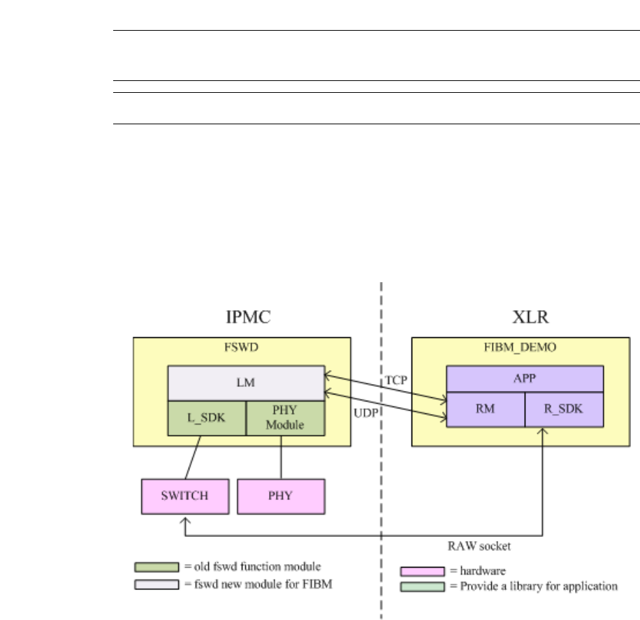
Page 8-185
CC06786-11B
Confidential and Proprietary
Network Configuration
1
4ABAB
Preliminary
8.2.3 FIBM Mode
Fulcrum In Band Management (FIBM) was made available in the PP50 release 1.3
Update 2. A Local Management (LM) module was added that allows the switch to
be bootstrapped into FIBM mode. In this mode, fswd does not use the local SDK to
read or write fulcrum registers. The CLI, web interface, and SNMP are also disabled.
Note: Contact your Continuous Computing representative for further
details regarding using FIBM.
Note: FIBM is only supported on Wind River (WR PNE LE).
Figure 8-2: Fulcrum In Band Management (FIBM)

Page 8-186
User Manual
Continuous Computing Corporation
FlexPacket ATCA PP50 Packet Processor
Preliminary
8.2.3.1 Enabling FIBM Mode
Follow the instructions below to enable the board for FIBM mode.
1. Set KV key as shown below:
'cn_fibm_enable' as "fibm XLR0XG0 10.4.41.136 10541"
where
'fibm' flag, fswd working on fibm/normal mode.
'XLR0XG0' device for switch control by remote SDK.
XLR0XG0 - cpu xlr0 eth4 port
XLR0XG1 - cpu xlr0 eth5 port
XLR1XG0 - cpu xlr1 eth4 port
XLR1XG1 - cpu xlr1 eth5 port
'10.4.41.136' ipmc TCP address, used to communicate with the user.
'10541' ipmc TCP port, used to communicate with the user.
2. Reboot the board.

Page 8-187
CC06786-11B
Confidential and Proprietary
Network Configuration
1
4ABAB
Preliminary
8.3 Base Switch Management and Port Connectivity
The base switch lets you add a port specific tag to an incoming packet and multiple
VLAN tagging (with no inherent limit other than packet length). These abilities
allow the PP50 to work with packets that are already singly or doubly tagged.
The base switch supports removing the outermost VLAN tag as the packet egresses
from the switch. This allows the VLAN partitioning to occur transparently to the
application and end devices, and allows the one physical switch to function as mul-
tiple independent virtual switches.
Aport can be a member of multiple VLANs and packets exiting the switch can retain
the VLAN tag identifying which VLAN the packet belongs to. This mode allows a
single physical port to send traffic to multiple destination networks on a packet by
packet basis.
The Ethernet data path is facilitated through a 10GbE capable switch. The FM2112
contains eight 10GbE interfaces and sixteen 1GbE interfaces.
The fabric interface to the AdvancedTCA backplane can be configured as a build
time option for 10GbE or for up to 4x 1GbE operation. In 10GbE operation, Ports 7
and 5 are wired to all 4 ports in channels 1 and 2. In four 1GbE operation, Ports 7
and 5 are put in 1GbE mode and make up the ‘A’ ports of the two fabric channels.
Switch ports [15 19 13] make up ports [b c d] for channel 1, and likewise switch ports
[21 11 9] make up ports [b c d] for Fabric channel 2.
8.3.1 Default Behavior
The linux ethernet driver in the IPMC had originally been modified to enable using
the Broadcom BCM5389 switch in a “statically managed” mode. This allowed the
processor with a single ethernet NIC to present two virtual broadcast domains (A
and B) to the system. A VLAN with ID 4094 was established at startup time, and any
entity wishing to send packets to the ‘B’ network needed to use that VLAN.
Table 8-1: Virtual Broadcast Domains
Network A Network B
XLR0 gmac2 XLR0 gmac3
XLR1 gmac2 XLR1 gmac3
Base Channel A Base Channel B
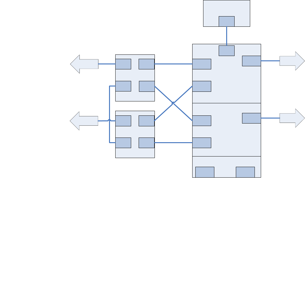
Page 8-188
User Manual
Continuous Computing Corporation
FlexPacket ATCA PP50 Packet Processor
Preliminary
Figure 8-3: PP50 Channel A and B Networks
8.3.1.1 Broadcom Management Tag (BMT)
A limited set of commands can be issued to the BCM5389 with a 6-byte tag (BMT)
that is inserted by the driver on egress from the processor, and by the switch on
ingress to the processor. On egress from the NIC, the driver inserts an opcode of
0x60 and an argument of either:
1. 0xd5 for the channel ‘A’ destinations if there is no VLAN tag in the packet
received from the upper layers OR
2. 0x2a for the channel “B” destinations if there is any VLAN tag, regardless of ID.
The VLAN tag will be stripped.
Bswitch unused
Bswitch part B
IPMC μC
(PPC405 )
Bswitch part A
MGT
PORT
PORT 0
PORT 1
PORT 6
PORT 5
PORT 2
PORT 7
Front Panel
PORT 4
PORT 3
eth0
Front Panel
Base
Channel B
XLR1
gmac2
gmac1
gmac0
gmac3
XLR0
gmac2
gmac1
gmac0
gmac3
Base
Channel A

Page 8-189
CC06786-11B
Confidential and Proprietary
Network Configuration
1
4ABAB
Preliminary
On ingress to the NIC, the driver removes the BMT. If the packet ingressed to the
bswitch from one of the base channel B ports, a VLAN tag with an ID of 4094 is
inserted from the base channel B ports or does nothing for packets ingressing from
base channel A ports.
8.3.1.2 Register Initialization in u-boot
For frames ingressing on bswitch ports other than the management port, an addi-
tional mask can be laid over the BMT egress map.
An ingress mask is applied to the bswitch at u-boot time, and persists in linux. The
mask applies to ingress packets at each port. For this discussion, the former will be
known as “selective-mask” and the latter will be “flooded.”
Table 8-3 "Selective-mask bswitch Ingress Masks" and Figure 8-4 "Selective-mask
bswitch Ingress Masks" show an example ingress mask. The ingress mask can be
changed in Linux using the virtual emac method if desired.
Table 8-2: VLAN assignment to ingress packets
Ingressing from bswitch port connection Action
0 Base Channel A none
1 Base Channel A insert VLAN ID 4094
2 XLR0 gmac2 none
3 XLR0 gmac3 insert VLAN ID 4094
4 XLR1 gmac2 none
5 XLR1 gmac3 insert VLAN ID 4094
6nonenone
7nonenone
Table 8-3: Selective-mask bswitch Ingress Masks
For frames ingressing
at Port Mask Binary Allows Egressing at
Port
0 111 1 0001 0001 0,4,8
1 122 1 0010 0010 1,5,8
2 0cc 0 1100 1100 2,3,6,7
3 0cc 0 1100 1100 2,3,6,7
4 111 1 0001 0001 0,4,8
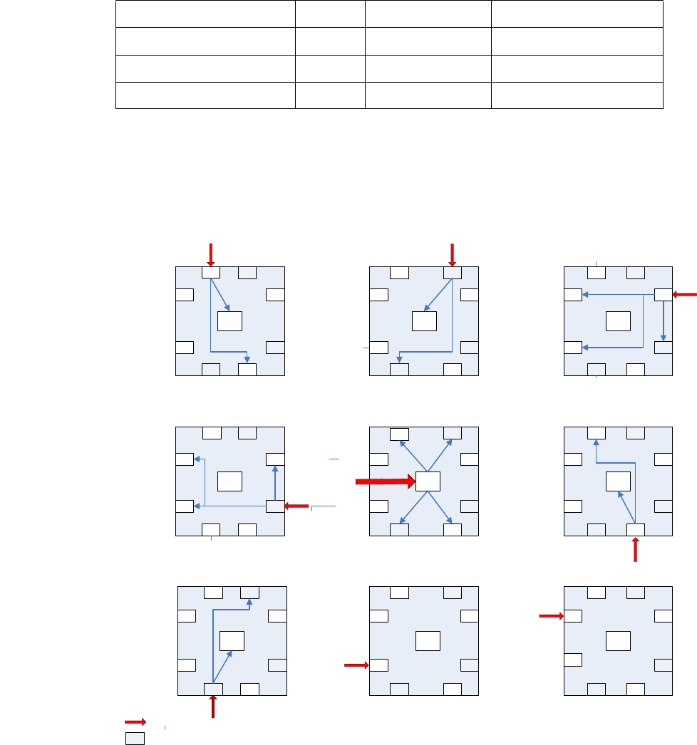
Page 8-190
User Manual
Continuous Computing Corporation
FlexPacket ATCA PP50 Packet Processor
Preliminary
Figure 8-4: Selective-mask bswitch Ingress Masks
5 122 1 0010 0010 1,5,8
6 04c 0 0100 1100 2,3,6
7 18c 1 1000 1100 2,3,7,8
8 (IMP) 1d3 1 1101 0011 0,1,4,6,7,8
Table 8-3: Selective-mask bswitch Ingress Masks
MGT
01
6
5
27
4
3
MGT
0 1
6
5
27
4
3
MGT
0 1
6
5
27
4
3
MGT
01
6
5
27
4
3
MGT
0 1
6
5
27
4
3
MGT
0 1
6
5
27
4
3
MGT
0 1
6
5
27
4
3
MGT
01
6
5
27
4
3
MGT
0 1
6
5
27
4
3
base ch A base ch B
XLR 0 gmac2
XLR 0 gmac3
XLR 1 gmac2XLR 1 gmac 3
unused
unused
base ch B base ch B
base ch B base ch B base ch B
base ch B base ch B base ch B
base ch A base ch A
base ch A base ch A base ch A
base ch A base ch A base ch A
XLR 0 gmac 2
XLR 0 gmac2
XLR 0 gmac2 XLR 0 gmac 2 XLR 0 gmac2
XLR 0 gmac2 XLR 0 gmac 2 XLR 0 gmac2
XLR 0 gmac 3 XLR 0 gmac3
XLR 0 gmac3
XLR 0 gmac 3 XLR 0 gmac3
XLR 0 gmac3XLR 0 gmac 3XLR 0 gmac3
XLR1 gmac2 XLR 1 gm ac 2
XLR 1 gmac2 XLR1 gmac2 XLR 1 gmac2
XLR 1 gmac2 XLR1 gmac2 XLR 1 gm ac 2
XLR1 gm ac3 XLR 1 gm ac 3
XLR1 gm ac3 XLR 1 gm ac 3XLR 1 gmac 3
XLR1 gm ac3XLR 1 gmac 3 XLR1 gmac3
unused unused
unused unused unused
unused unused
unused
unused unused
unused unused unused
unused
unused
unused
3
ingress
eth0.4094
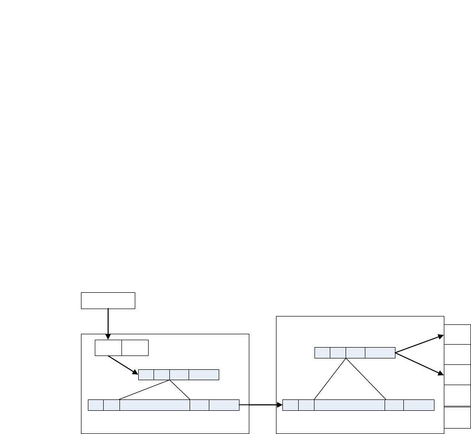
Page 8-191
CC06786-11B
Confidential and Proprietary
Network Configuration
1
4ABAB
Preliminary
8.3.2 Configurable Behavior
For even more powerful selective routing of packets through the bswitch, two other
methods are provided. The methods use the same basic steering technique as
described above, but instead of using a pre-defined VLAN ID, the IPMC upper net-
work layers are presented with “virtual” (or fake) ethernet NICS. Up to 7 virtual
EMACs can be added, giving applications the choice of communicating via eth0,
eth1 through eth7.
One method (VLAN Mode) associates a VLAN ID with each virtual EMAC. That
VLAN ID is presented to the rest of the system as normal 802.1q packets, but inter-
nal to the IPMC there is no VLAN ID. The traffic is identified strictly by which
virtual EMAC it appears on.
The other method (BMT Mode) does not attach VLAN headers to system packets – it
simply steers the packets through the bswitch depending on which virtual EMAC
they belong to.
The power of these schemes is in enabling a bonding driver in the IPMC to be able
to switch virtual networks if one of the redundant networks in the system goes
down. In other words, it behaves like the other processor elements in the system
that have multiple physical NICs.
The same functionality is available on the Continuous Computing FM40 hub switch
and XE50 compute blades.
Figure 8-5: BMT Mode eth0 egress
driver
netw or k l ayer
eth 1eth 0
BCM 5389 switch
DA SA TYPE PAYLOAD
BCM TAG
OPCODE= 60 DATA=b 0101
DA SA TYPE PAYLOAD
DA SA TYPE PAYLOAD
BCM TAG
OPCODE= 60 DATA =b0101
DA SA TYPE PAYLOAD
PORT 0
PORT 1
PORT 2
PORT 3
/proc/ sys/net/ipmc/fake_eth0/ emask = 0 x5
/proc/sys/net/ ipmc/fake_eth1/emask = 0xA
PORT N ...
Page 8-192
User Manual
Continuous Computing Corporation
FlexPacket ATCA PP50 Packet Processor
Preliminary
Figure 8-6: BMT Mode eth1 egress
Figure 8-7: BMT Mode eth1 ingress
driver
networ k layer
eth 1eth 0
BCM 5389 switch
DA SA TYPE PAYLOAD
BCM TAG
OPCODE= 60 DATA=b 1010
DA SA TYPE PAYLOAD
DA SA TYPE PAYLOAD
BCM TAG
OPCODE= 60 DATA =b1010
DA SA TYPE PAYLOAD
PORT 0
PORT 1
PORT 2
PORT 3
/pr oc /sys/net /ipmc/fake _eth 0/emask = 0 x5
/proc/sys/ net/ipmc/fake_eth1/emask = 0xA
PORT N ...
driver
networ k layer
eth 1eth 0
BCM 5389 switch
DA SA TYPE PAYLOAD
BCM TAG
OPCODE =0 SrcPortID =1
DA SA TYPE PAYLOAD
DA SA TYPE PAYLOAD
BCM TAG
OPCODE =0 SrcPortID =1
DA SA TYPE PAYLOAD
PORT 0
PORT 1
PORT 2
PORT 3
/pr oc /sys/net /ipmc/fake _eth 0/emask = 0 x5
/proc/sys/ net/ipmc/fake_eth1/emask = 0xA
PORT N ...
Page 8-193
CC06786-11B
Confidential and Proprietary
Network Configuration
1
4ABAB
Preliminary
Figure 8-8: VLAN Mode eth0 egress
Figure 8-9: VLAN Mode eth1 egress
driver
netw ork l ay er
eth 1eth 0
BCM5389 sw itch
BCM TAG
OPCODE=0 DATA=x
DA SA TYPE PAYLOAD
DA SA TYPE PAYLOAD
DA SA TYPE PAYLOAD
PORT 0
PORT 1
PORT 2
PORT 3
/proc /sys/net /ipmc/fake_eth 0/vid = 100
/proc /sys/net /ipmc/fake_eth 1/vid = 200
PORT N ...
BCM TAG
OPCODE=0 DATA=x
DA SA TYPE PAYLOAD
VLAN TAG
VID = 100 (0x64 )
BCM TAG
OPCODE=0 DATA=x
DA SA TYPE PAYLOAD
VLAN TAG
VID = 100 (0x64 )
VLAN TAG
VID = 100 (0x64)
driver
network layer
eth 1eth 0
BCM5389 switch
BCM TAG
OPCODE=0 DATA=x
DA SA TYPE PAYLOAD
DA SA TYPE PAYLOAD
DA SA TYPE PAYLOAD
PORT 0
PORT 1
PORT 2
PORT 3
/ proc/sys/ net /ipmc/fake_ eth0/vid = 100
/ proc/sys/ net /ipmc/fake_ eth1/vid = 200
PORT N ...
BCM TAG
OPCODE=0 DATA=x
DA SA TYPE PAYLOAD
VLAN TAG
VID = 200 (0xC8)
BCM TAG
OPCODE=0 DATA=x
DA SA TYPE PAYLOAD
VLAN TAG
VID = 200 (0 xC8)
VLAN TAG
VID = 200 (0 xC8)

Page 8-194
User Manual
Continuous Computing Corporation
FlexPacket ATCA PP50 Packet Processor
Preliminary
8.3.3 Alternate bswitch Behavior
The key value “cnswmode” can be used to change the bswitch programming in u-
boot.
8.3.4 Configuration
The virtual EMACs are configured using the linux “sysconfig” method, which
allows the user to control system parameters and behavior via virtual files in the /
proc directory.
The num_of_fakes and vlan_method variables are global to the driver. The
num_of_fakes is set by a key value "cnnumofveths". The vlan_method variable can be
changed in real time.
8.3.4.1 num_of_fakes:
when zero, the ibm_emac driver behaves exactly as it did before any of the virtual
EMAC modifications. Only one ethernet interface is presented to the upper net-
work layers. The sysctl files have no effect. When non-zero, the number of ethernet
interfaces presented to the upper layers is 1 + n (where n = num_of_fakes).
8.3.4.2 vlan_method
When non-zero, the packets are sent to the BCM5389 with a VLAN tag attached.
The VID is set by the sysctl file /proc/sys/net/ipmc/fake_ethn/vid.
When vlan_method is zero, there is no VLAN tag. Instead, the Broadcom Manage-
ment Tag (BMT) is set to opcode 0x60 with the egress mask set by the sysctl file /
proc/sys/net/ipmc/fake_ethn/emask.
Table 8-4: cnswmode Values
cnswmode
value Action
hub network A and B split as described above
static Same as “hub,” but programs on-blade MAC addresses into
learning table to improve CNode processor network performance
flood All ports connect to all ports. WARNING – can cause network
storms if not used with extreme caution – not recommended
“NULL” (no
entry)
defaults to “hub” mode

Page 8-195
CC06786-11B
Confidential and Proprietary
Network Configuration
1
4ABAB
Preliminary
Figure 8-10: sysctl tree
8.3.5 Design Overview
If the CNode key value cnnumofveths is not set or doesn’t exist, the driver behaves
exactly the same as it did before. Otherwise, a number of virtual (fake) NICs are
simulated by the driver. These will all have the same hardware address as the
actual NIC, but they can be configured to have unique IP addresses.
/
/proc
/sys
/net
/ipmc
fake_eth1
fake_eth0
fake_ethn
vlan_method
num_of_fakes
vid
emask
vid
vid
emask
emask
debug _level

Page 8-196
User Manual
Continuous Computing Corporation
FlexPacket ATCA PP50 Packet Processor
Preliminary
8.3.5.1 VLAN mode
In this mode, the driver applies an 8021Q VLAN to the egress packet and examines
the VID of ingressing packets. If the VID of an incoming packet is one that is listed
in the corresponding sysctl variable, the VLAN tag is stripped and the packet is pre-
sented to the appropriate eth interface. For example, if /proc/sys/net/ipmc/
fake_eth0/vid is set to 4094 and /proc/sys/net/ipmc/fake_eth1/vid is set to 4093,
a packet sent out from eth1 will have the VID 4093 applied at egress. If a packet
comes in with a VID of, say 3000, the VLAN tag is left unmolested and the packet is
delivered up to the default eth interface (eth0). If the VID had been 4094, the VLAN
tag would be stripped and the packet delivered to eth0.
8.3.5.2 BMT Mode
In this mode, an egress mask is applied to the Broadcom Management Tag (BMT)
according to a 9-bit mask set in a proc/sys entry for a particular virtual EMAC.
The following mask will flood ports 1, 3 and 5 (0x02a).
The following will flood ports 0, 2, 4, 5 and 7 (0x0d5)
When a packet is received by the driver from the switch, its BMT is examined for the
source port information. The /proc/sys/net/ipmc/fake_ethn/emask variable is
ANDed with the source port value. The emask variables are taken in ascending
order, so the first match is the one that is applied. If a match is found, the packet is
delivered up to the associated ethernet interface. If no match is found, the packet is
discarded. For example, if /proc/sys/net/ipmc/fake_eth0/emask is set to 0x05
and /proc/sys/net/ipmc/fake_eth1/emask is set to 0x0a, a packet from the switch
with BMT source port field = 0x04 (from port 3) will be presented to eth1. A packet
with BMT source port = 0x10 (from port 4) will be discarded.
Table 8-5: BMT mode Flood Ports
BRCM Opcode Forward Map
88 74 60 00 00 2a
Table 8-6: BMT mode Flood Ports
BRCM Opcode Forward Map
88 74 60 00 00 d5

Page 8-197
CC06786-11B
Confidential and Proprietary
Network Configuration
1
4ABAB
Preliminary
8.3.6 Key Value Database Syntax
This is the default mode of configuring the product. The key name is “cnnu-
mofveths” (short for CNode number of virtual ethernets)
If cnnumofveths is non-existent, the driver will initialize the num_of_fakes variable
to 0 and default behavior is preserved.
8.3.7 Examples
8.3.7.1 VLAN method
Set key value and reboot
Set VLAN method
Set eth0 VID to 100 and eth1 VID to 200
Bring up eth0 and eth1
Set up a remote host to be a member of VLAN 100 and ping IPMC eth0
Ping should be successful.
Remove remote host from VLAN 100 and add to VLAN 200
Ping should be successful.
cnodekv cnnumofveths 1
reboot
echo 1 > /proc/sys/net/ipmc/vlan_method
cd /proc/sys/net/ipmc/
echo 100 > fake_eth0/vid
echo 200 > fake_eth1/vid
ifconfig eth0 192.168.43.1
ifconfig eth1 192.168.44.1
ifconfig eth0 0.0.0.0
modprobe 8021q
vconfig add eth0 100
ifconfig eth0.100 192.168.43.3
ping –I 192.168.43.3 192.168.43.1
vconfig rem eth0.100
vconfig add eth0 200
ifconfig eth0.200 192.168.44.3
ping –I 192.168.44.3 192.168.44.1

Page 8-198
User Manual
Continuous Computing Corporation
FlexPacket ATCA PP50 Packet Processor
Preliminary
8.3.7.2 Mask Method
The following will assign IPMC eth0 to the “A” network and eth1 to the “B” net-
work, see Figure 8-3 "PP50 Channel A and B Networks" for details.
Set key value and reboot
Set vlan_method to 0
Set mask for eth0 to ports 0, 2 and 4
Set mask for eth1 to ports 1, 3 and 5
Bring up eth0 and eth1
Assuming linux is loaded on XLR0, configure XLR0 gmac2 to network “A” subnet
Configure XLR0 gmac3 to network “B” subnet
The IPMC can now be pinged from both NICS.
8.3.8 Front Mode
In this mode, the 10G ports are connected directly to the front panel 10G connectors.
8.3.9 RTM Mode
In this mode, the 10 G ports are connected directly to the RTM port.
cnodekv cnnumofveths 1
reboot
echo 0 > /proc/sys/net/ipmc/vlan_method
echo 0x15 > /proc/sys/net/ipmc/fake_eth0/emask
echo 0x2a > /proc/sys/net/ipmc/fake_eth1/emask
ifconfig eth0 192.168.43.1
ifconfig eth1 192.168.44.1
ifconfig eth2 192.168.43.2
ifconfig eth3 192.168.44.2
echo 0x2a > /proc/sys/net/ipmc/fake_eth1/emask
ping –I eth2 192.168.43.1
ping –I eth3 192.168.44.1b

Page 8-199
CC06786-11B
Confidential and Proprietary
Network Configuration
1
4ABAB
Preliminary
8.4 Ethernet Ports on the RTM
There are twelve Ethernet ports on the Rear Transition Module (RTM), ten 1GbE
ports and two 10G ports. The 10G ports on the RTM and front panel are jointly
routed to either the front panel or RTM with the fswcmd command.
8.5 Fabric and Base Switch Management
The PP50’s base and fabric switches are isolated and can be considered "lightly man-
aged." Generally, management and administration traffic flows over the base switch
and data plane traffic flows over the fabric plane. The control plane can be on either
switch, depending on the application.

Page 8-200
User Manual
Continuous Computing Corporation
FlexPacket ATCA PP50 Packet Processor
Preliminary
8.6 CNode Base Switch (bswcmd) Command
Base Switch Command, provides base switch operation and information.
The bswcmd command can run on either the IPMC or XLR (RMI Linux or Win-
dRiver Linux) but it relies on a daemon called bswd which is runs on the IPMC
(only the IPMC).
8.6.1 Binding bswcmd to the CNODE's IP
For an XLR to run bswcmd, a configuration file named bswcmd.cfg with the IPMC’s
(and bswd) IP address in it must be created in the command file’s directory. For
example, if the IPMC IP address is 10.4.1.10, put the following line into the config
file
ip_address 10.4.1.10
The configuration file may also be created by using the bind command shown
below.
8.6.2 bswcmd Usage Examples
Below are examples for using the bswcmd command.
8.6.2.1 Common bswcmd Commands
bswcmd
bswcmd list
Note: You must bind bswcmd to the CNODE's IP before using it, example
below.
root@localhost:/pp50-xlr-utils-v2.2.6r00/xlr-utils# ./bswcmd bind 172.17.3.147
Bound to destination 172.17.3.147 ipaddress
Attempting to route over eth0 ,eth2 and eth3....
root@cnode-pp50:~ bswcmd
Specify Arguments
Use: bswcmd list - To view the list of supported commands
Use: bswcmd bind <valid ip address> before using bswcmd list command
root@cnode-pp50:~ bswcmd list
enable port <port id> | <all>
disable port <port id> | <all>
- enable or disable the (tx and rx) function of ports (0 and 1)
show link <port id> <all>
- Shows the link admin state and link state
show statistics <port id> | <all>
- Displays variable statistics of the port(s)
get-link-check
- Writes the link state Into the Logfile /tmp/link_status

Page 8-201
CC06786-11B
Confidential and Proprietary
Network Configuration
1
4ABAB
Preliminary
bswcmd show link all
bswcmd show statistics all
show statistics <port id> | <all>
- Displays variable statistics of the port(s)
bind <ip address>
- Binds bswcmd to an IPMC IP Address
root@cnode-pp50:~
root@cnode-pp50:~ bswcmd show link all
--------------------------------------------------------------------
PORT ADMIN STATE LINK STATE SPEED(MBPS) CONNECTION NAME
---- ----------- ---------- ----------------------------------------
0 ENABLED UP 1000 IPMC BASE CHANNEL A
1 ENABLED UP 1000 IPMC BASE CHANNEL B
2 ENABLED UP 1000 XLR0 GMAC2
3 ENABLED UP 1000 XLR0 GMAC3
4 ENABLED UP 1000 XLR1 GMAC2
5 ENABLED UP 1000 XLR1 GMAC3
6 ENABLED DOWN 10 NONE UNUSED
7 ENABLED DOWN 10 NONE UNUSED
root@cnode-pp50:~ bswcmd show statistics all
================================================================================
Base PORT 0 1 2 3 4 5 6 7
================================================================================
TxOctets 21423 0 292069 25091 292069 25091 0 0
TXDropPkts 0 0 0 0 0 0 0 0
TxQoSPkts 215 0 215 0 215 0 0 0
TxBroadcastPkts 2 0 1512 2 1512 2 0 0
TxMulticastPkts 0 0 1071 195 1071 195 0 0
TxUnicastPkts 213 0 432 0 432 0 0 0
TxCollisions 0 0 0 0 0 0 0 0
TxSingleCollision 0 0 0 0 0 0 0 0
TxMultipleCollision 0 0 0 0 0 0 0 0
TxDeferredTransmit 0 0 0 0 0 0 0 0
TxLateCollision 0 0 0 0 0 0 0 0
TxExcessiveCollision 0 0 0 0 0 0 0 0
TxFrameInDisc? 0 0 0 0 0 0 0 0
TxPausePkts 0 0 0 0 0 0 0 0
TxQoSOctets 21423 0 21423 0 21423 0 0 0
RxOctets 270710 25091 0 0 0 0 0 0
RxUndersizePkts 0 0 0 0 0 0 0 0
RxPausePkts 0 0 0 0 0 0 0 0
Pkts64Octets 1470 0 0 0 0 0 0 0
Pkts65to127Octets 240 195 0 0 0 0 0 0
Pkts128to255Octets 1057 0 0 0 0 0 0 0
Pkts256to511Octets 23 2 0 0 0 0 0 0
Pkts512to1023Octets 11 0 0 0 0 0 0 0
Pkts1024to1522Octets 0 0 0 0 0 0 0 0
RxOversizePkts 0 0 0 0 0 0 0 0
RxJabbers 0 0 0 0 0 0 0 0
RxAlignmentErrors 0 0 0 0 0 0 0 0
RxFCSErrors 0 0 0 0 0 0 0 0
RxGoodOctets 270710 25091 0 0 0 0 0 0
RxDropPkts 0 0 0 0 0 0 0 0
RxUnicastPkts 219 0 0 0 0 0 0 0
RxMulticastPkts 1071 195 0 0 0 0 0 0
RxBroadcastPkts 1511 2 0 0 0 0 0 0
RxSAChanges 2371 2 0 0 0 0 0 0

Page 8-202
User Manual
Continuous Computing Corporation
FlexPacket ATCA PP50 Packet Processor
Preliminary
8.6.3 Fabric Switch
The fabric switch may be configured locally or remotely. See Chapter8.2, "Fabric
Switch Management" for more information on configuring the fabric switch.
RxFragments 0 0 0 0 0 0 0 0
RxExcessSizeDisc 0 0 0 0 0 0 0 0
RxSymbolError 0 0 0 0 0 0 0 0
RXQOSPkt 0 0 0 0 0 0 0 0
RXQOSOctets 0 0 0 0 0 0 0 0
Pkts1523to2047 0 0 0 0 0 0 0 0
Pkts2048to4095 0 0 0 0 0 0 0 0
Pkts4096to8191 0 0 0 0 0 0 0 0
Pkts8192to9728 0 0 0 0 0 0 0 0
Pkts2048to4095 0 0 0 0 0 0 0 0

Page 8-203
CC06786-11B
Confidential and Proprietary
Network Configuration
1
4ABAB
Preliminary
8.7 Configuring XLR Network Interfaces using KV
The KV variable can be used to assign IP addresses to ethernet ports after Linux has
booted up. Please note that Linux utilities should be installed to use this feature. The
following table lists the KV variables used for this purpose.
The KV variable for XLR1 will start with prefix s1_*
Table 8-7: XLR Ethernet ports and their corresponding key values
Ethernet Interface Key value Description
XLR0:eth0 s0_ge_proto static / dhcp
s0_ge_ipaddr IP address
s0_ge_mask IP Mask
XLR0:eth1 s0_ig_proto static / dhcp
s0_ig_ipaddr IP address
s0_ig_mask IP Mask
XLR0:eth2 s0_bsa_proto static / dhcp
s0_bsa_ipaddr IP address
s0_bsa_mask IP Mask
XLR0:eth3 s0_bsb_proto static / dhcp
s0_bsb_ipaddr IP address
s0_bsb_mask IP Mask
XLR0:eth4 s0_xg0_proto static / dhcp
s0_xg0_ipaddr IP address
s0_xg0_mask IP Mask
XLR0:eth5 s0_xg1_proto static / dhcp
s0_xg1_ipaddr IP address
s0_xg1_mask IP Mask
s0_gatewayip Gateway
s0_nameserver Name Server

Page 8-204
User Manual
Continuous Computing Corporation
FlexPacket ATCA PP50 Packet Processor
Preliminary
8.7.1 Configuring XLR Network Interfaces Example
To have Linux configure eth0 of XLR0 into static mode automatically, set the follow-
ing key-value items.
If you want Linux to configure eth2 of XLR0 into dhcp mode automatically, set the
following key-value item.
To implement the key values set above simply reboot Linux.
root# kv s0_ge_proto static
root# kv s0_ge_ipaddr 10.4.69.34
root# kv s0_ge_mask 255.255.0.0
root# kv s0_gateway 10.4.0.254
root# kv s0_nameserver 10.4.1.30
root# kv s0_bsa_proto dhcp

Page 9-205
CC06786-11B
Confidential and Proprietary
9
Preliminary
9Using Wind River Linux on the PP50
This chapter provides instructions on how to install and compile the optional (not
required) Wind River Linux Platform for Network Equipment Limited Edition oper-
ating system (WR PNE-LE) in the following sections.
Note: For installing WR PNE-LE updates please see WindRiver’s
documentation.

Page 9-206
User Manual
Continuous Computing Corporation
FlexPacket ATCA PP50 Packet Processor
Preliminary
9.1 Overview
There are a few basic steps to installing and using WR PNE-LE on PP50s:
1. Get the source files, Section9.1.2, "Installation Requirements"
2. Install it, Section9.2.1, "Installation Steps for WindRiver PNE 2.0"
3. Set it up, Section9.5, "Linux Setup"
4. Use it, Section9.6, "Linux Command Line Options"
9.1.1 CCPU/WindRiver Release Compatibility
The board’s BSP is WindRiver release specific. Use the table below for quick refer-
ence. As future releases are done this will serve a matrix.
Note: WindRiver may release additional patches after publication of this
document. If a file listed here is not available from WindRiver,
contact Continuous Computing customer service for compatibility
guidance.
Table 9-1: CCPU/WindRiver Release Compatibility
CCPU Release WindRiver Required Files
PP50 V1.3upd3 • WindRiver PNE LE 2.0 (Three DVDs)
• Update Pack 4 for Wind River Linux 2.0
( DVD-R128063.1-1-04.iso )
• (WRL_2_0_4-layer-wrll-linux-2.6.21-20101201-spin1.zip)

Page 9-207
CC06786-11B
Confidential and Proprietary
Using Wind River Linux on the PP50
1
4ABAB
Preliminary
9.1.2 Installation Requirements
This section describes the installation requirements.
9.1.2.1 For WindRiver PNE LE 2.0
WR-PNE version 2.0 installed on a development x86 server.
• The files listed below.
Figure 9-1: WindRiver PNE LE 2.0 Files for CCPU Release 1.3
File Function Source
DVD-R128063.1-
1-04.iso
Update Pack 4 for Wind River Linux 2.0
Cumulative patches for Wind River
Linux 2.0 - Replaces and Supersedes
Service Packs 1-3
These files can be
purchased from
Wind River and
downloaded from
their support web
site. Contact Wind
River for details.
WRL_2_0_4-
layer-wrll-linux-
2.6.21-20101201-
spin1.zip
Wind River Linux 2.0 UP 4 Cumulative
patch for wrll-linux-2.6.21
Requires Wind River Linux 2.0 Update
Pack 4 (2.0.4) to be installed.

Page 9-208
User Manual
Continuous Computing Corporation
FlexPacket ATCA PP50 Packet Processor
Preliminary
9.2 Installing the Template and Patch
This chapter provides instructions on how to install and compile the optional (not
required) Wind River Linux Platform for Network Equipment Limited Edition
operating system (WR PNE-LE) in the following sections.
9.2.1 Installation Steps for WindRiver PNE 2.0
1. Install WindRiver PNE 2.0.
2. Install service pack 4 for WindRiver PNE 2.0.
3. Install the patches.
4. Install PP50 support for PNE LE
Note: These instructions assume that WindRiver PNE is installed to
/home/devel/WindRiver and the CCPU BSP package and file
WRL_2_0_4-layer-wrll-linux-2.6.21-20101201-spin1.zip has been put into
the /tmp folder.
cd /home/devel/WindRiver/updates
cp /tmp/WRL_2_0_4-layer-wrll-linux-2.6.21-20101201-spin1.zip ./
unzip WRL_2_0_4-layer-wrll-linux-2.6.21-20101201-spin1.zip
../maintenance/mtool/mtool_linux
cd /tmp
tar -xzf pp50-wr-linux-vx.x.xrxx.tar.gz
cd pp50-wr2.0-release
./bsp_install /home/devel/WindRiver
./package_install /home/devel/WindRiver
Page 9-209
CC06786-11B
Confidential and Proprietary
Using Wind River Linux on the PP50
1
4ABAB
Preliminary
9.3 Building the Kernel and NFS
Follow these instructions to create the kernel and root system files.
1. Start WindRiver Work Bench
2. Start a New Project
At Workbench GUI, select menu "File->New->Wind River Linux Platform Project"
to create a new project.
Figure 9-2: Create a New Project
cd /home/devel/WindRiver
./startWorkbench.sh
Page 9-210
User Manual
Continuous Computing Corporation
FlexPacket ATCA PP50 Packet Processor
Preliminary
At the Project window, input your Project name, then click Next.
Figure 9-3: Input the Name
At the Configure Options window select:
• Board: ccpu_xlr_pp50p2,
And one of the following pairs depending on whether you want a CGI or standard
system and kernel:
• RootFS: glibc_cgi and Kernel: CGI
or
• RootFS: glibc_std and Kernel: standard
and the default settings for the rest of the parameters.
Page 9-211
CC06786-11B
Confidential and Proprietary
Using Wind River Linux on the PP50
1
4ABAB
Preliminary
Then click NEXT .
Figure 9-4: Select Board
Page 9-212
User Manual
Continuous Computing Corporation
FlexPacket ATCA PP50 Packet Processor
Preliminary
At the Static Analysis window, click Finish button.
Figure 9-5: Static Analysis
3. Configure Project Options
You will see the project name PP50 in the Project Tab.
Figure 9-6: Project Name
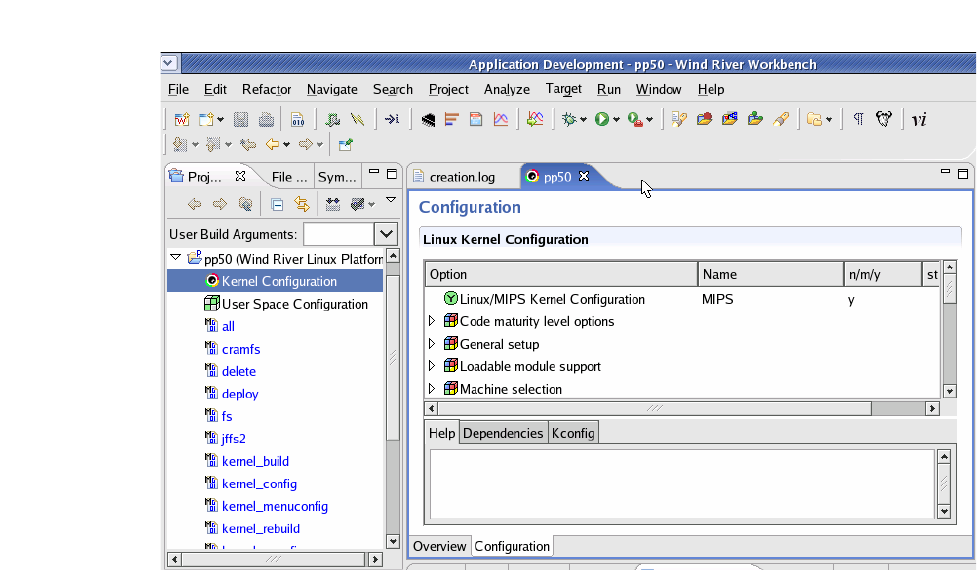
Page 9-213
CC06786-11B
Confidential and Proprietary
Using Wind River Linux on the PP50
1
4ABAB
Preliminary
Double click "Kernel Configuration" at PP50 project tab to unpack WindRiver linux
kernel for the project.
The PP50 will compile with the default options for the kernel, but these can be mod-
ified on this screen to meet specific project requirements. .
Figure 9-7: Linux Kernel Configuration
Double click "User Space Configuration" at PP50 project tab to set up your NFS
package.
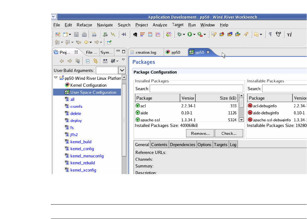
Page 9-214
User Manual
Continuous Computing Corporation
FlexPacket ATCA PP50 Packet Processor
Preliminary
Default options will work for the PP50, but these can be modified on this screen to
meet specific project requirements.
Figure 9-8: Package Configuration
4. Build the Kernel
Note: It will probably take more than one hour to build the kernel.
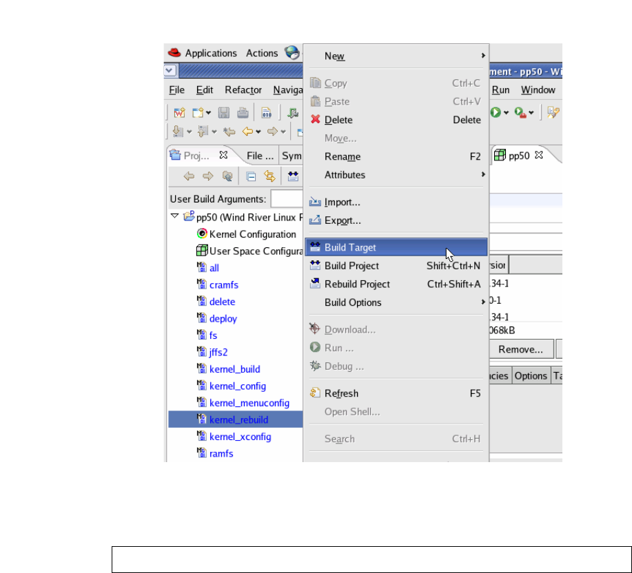
Page 9-215
CC06786-11B
Confidential and Proprietary
Using Wind River Linux on the PP50
1
4ABAB
Preliminary
Right click "kernel_rebuild" or "kernel_build" at PP50 Project Tab and select
"Build_Target" to build WindRiver linux kernel.
Figure 9-9: Build WindRiver Linux Kernel
5. Build the NFS File System.
Note: It will probably take more than 5 hours to build NFS File System.
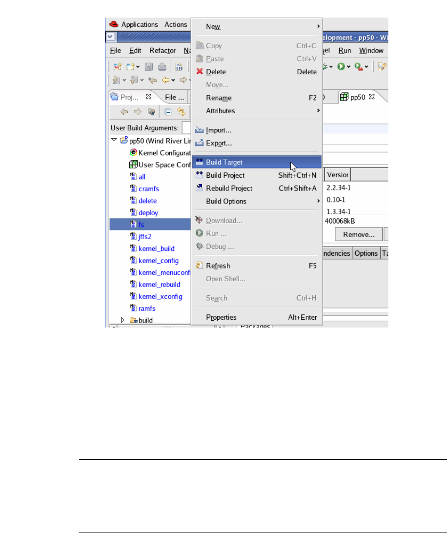
Page 9-216
User Manual
Continuous Computing Corporation
FlexPacket ATCA PP50 Packet Processor
Preliminary
Right click "fs" on the PP50 project tab and select "Build Target" to build the Win-
dRiver linux NFS.
Figure 9-10: Build WindRiver Linux NFS
6. Examine the output files.
In the directory /home/devel/WindRiver/workspace/pp50_prj/export
you should see two files: the linux kernel image and the and NFS tar file respec-
tively named in WindRiver PNE 2.0:
• ccpu_xlr_pp50p2-vmlinux-stripped-WR2.0bl_standard
• ccpu_xlr_pp50p2-glibc_std-standard-dist.tar.bz2
Note: Filenames used by and distributed by Continuous Computing may
be different from those of WindRiver. For example the WindRiver
Linux Kernel Image used in Continuous Computing development
is pp50-linux-kernel-wr-vx.x.x (x.x.x being version number) for
convenience but the content is the same.

Page 9-217
CC06786-11B
Confidential and Proprietary
Using Wind River Linux on the PP50
1
4ABAB
Preliminary
9.3.1 Installing the Boot Kernel and NFS
Install the kernel image ccpu_xlr_pp50p2-vmlinux-stripped-WR2.0bl_standard
from the previous section by copying them to the system's tftp directory:
Install the NFS File System ccpu_xlr_pp50p2-glibc_std-standard-dist.tar.bz2 from
the previous section by making a directory for the file system on the target blade
and untarring it there. This example uses: /home/devel/export/xlr_glibc_nfsroot/.
Install the NFS file system into the directory:
9.3.2 Booting the Target Blade
This example uses following network configuration:
Note: This chapter provides instructions on how to install and compile the
optional (not required) Wind River Linux Platform for Network
Equipment Limited Edition operating system (WR PNE-LE) in the
following sections.
cd /home/devel/WindRiver/workspace/pp50_prj/export
cp ccpu_xlr_pp50p2-vmlinux-stripped-WR2.0bl_standard/tftproot
mkdir -p /home/devel/export/xlr_glibc_nfsroot/
cd /home/devel/export/xlr_glibc_nfsroot
tar -xjf /home/devel/WindRiver/workspace/pp50_prj/ccpu_xlr_pp50p2-glibc_std-
standard-dist.tar.bz2
Table 9-2: Boot Target Blade Network Configuration
Linux Kernel Image
Name
ccpu_xlr_pp50p2-vmlinux-stripped-WR2.0bl_standard
(from previous section)
Linux Filesystem
Name
ccpu_xlr_pp50p2-glibc_std-standard-dist.tar.bz2
(from previous section)
TFTP Server Path 10.4.69.69:/tftproot
Debug Server 10.4.69.69
Gateway 10.4.0.254
NFS Server 10.3.8.225
Target (PP50 Blade) 10.4.69.2

Page 9-218
User Manual
Continuous Computing Corporation
FlexPacket ATCA PP50 Packet Processor
Preliminary
Connect to the serial console on the target PP50 blade and execute the following
commands at the bootloader:
The userapp command will start the kernel & pass in the parameters. The prototype
for these parameters is:
Once the blade has booted, log in as:
• username: root
• password: root
9.4 Memory Map Setup
To load applications in Linux, a physical address range needs to be reserved and
excluded from the Linux memory map. The current release excludes these regions
from the Linux Kernel memory.
Following are the default memory regions have been reserved in the current release
• 0x0c000000 to 0x10000000 for KSEG0 applications
• 0x20000000 to 0x40000000 for KUSEG applications.
However command line options are provided to change these memory regions. See
the following sections.
9.5 Linux Setup
1. Boot Linux with "xlr_loader" option.
2. Once Linux boots up, create a character device with the command:
3. Compile the applications provide by running "make all" command.
ifconfig -i gmac0 -a 10.4.69.2 -g 10.4.0.254
tftpc -s 10.4.69.69 -f ccpu_xlr_pp50p2-vmlinux-stripped-WR2.0bl_standard
elfload
userapp root=/dev/nfs nfsroot=10.3.8.225:/home/devel/export/
xlr_glibc_cgl_nfsroot ip=10.4.69.2:10.3.8.225:10.4.0.254:255.255.0.0::eth0:off
console=ttyS0,38400
userapp root=/dev/nfs nfsroot=serverip:/rootpath
ip=targetip:serverip:gateway:netmask::eth0:off console=ttyS0,38400
userapp xlr_loader
mknod /dev/xlr_app_loader c 245 0
mknod /dev/xlr_app_loader_1 c 245 1

Page 9-219
CC06786-11B
Confidential and Proprietary
Using Wind River Linux on the PP50
1
4ABAB
Preliminary
9.6 Linux Command Line Options
The following linux command line options are available.
9.6.1 linux_cpu_mask=<cpu_mask>
This defines the mask of CPUs in hex that run Linux. Any valid mask can be given
here and Linux will run on those CPUs. The remaining CPUS can be used for
RMIOS applications. The default Linux CPU mask is ffffffff
9.6.2 kseg0_start=<address>
This defines the start of physical memory in KSEG0 region to use for loading KSEG0
apps. This address must be:
• Greater than _end
• Multiple of 2MB
• Less than 0x10000000
9.6.3 kseg0_size=<size>
This defines the size of KSEG0 region in hex (no 0x prefix). The user must ensure
that enough memory has been reserved for Linux to run while configuring memory
size for the loader.
Note: The following command options and text use the term “CPU” is
used for legacy reasons, in most circles “thread” is a more term in
this application.
Note: Applications cannot be launched on a core that has Linux running
on a few threads unless the "shared_core" option is passed during
the kernel boot.
For example, linux_cpu_mask=0x3f, loader feature will be available
only on 0xffffff00 CPUs.
Note: Currently if kseg0_start and kseg0_size value are changed below
the default values mentioned above then loader may fail to launch
any kseg applications.

Page 9-220
User Manual
Continuous Computing Corporation
FlexPacket ATCA PP50 Packet Processor
Preliminary
9.6.4 kumem=<size@addr>
The fragment of physical memory that will be used for loading the KUSEG
applications.
• addr represents the start address of the physical segment.
• size represents the size of physical segment.
The size and addr can be represented in kilobytes k/K, MegaBytes M/m, or Giga-
Bytes g/G. The default unit of size and address is bytes.
Up to 4 fragments of memory can be specified for loading kuseg applications
• If one of the fragments is invalid, then the default size and address will be used,
ignoring the other valid arguments
• All the contiguous/overlapping regions are merged into a single large region
• KUSEG start must be greater than 512MB and a multiple of 2MB.
9.6.4.1 Examples of Using kumen
Use print_physmap to get the valid memory from the bootloader prompt.
9.6.4.1.1 One GB Example
memory: 000c000000 @ 0000100000 (usable)
memory: 002f000000 @ 0020000000 (usable)
Leaving the lower 512 MB, the valid memory region is from 512MB to 1264MB
for example, 752MB.
Example for allocating 512 MB of memory from two different locations:
or as continuous block
9.6.4.1.2 Two GB Example
memory: 000c000000 @ 0000100000 (usable)
memory: 006f000000 @ 0020000000 (usable)
Leaving the lower 512 MB, the valid memory region is from 512MB to 2288MB
in other words 1776MB.
Example for allocating 1152 MB of memory as a continuous segment:
userapp xlr_loader kumem=256M@3584M kumem=131072K@3968M kumem=128M@768M
kumem=128M@640M
$ userapp xlr_loader kumem=512M@1024M\
$ userapp xlr_loader kumem=256M@512M kumem=256M@1024M
$ userapp xlr_loader kumem=1152M@1024M

Page 9-221
CC06786-11B
Confidential and Proprietary
Using Wind River Linux on the PP50
1
4ABAB
Preliminary
Example for allocating 1152 MB of memory as a discrete segment:
9.6.4.1.3 Four GB Example
memory: 000c000000 @ 0000100000 (usable)
memory: 00a0000000 @ 0020000000 (usable)
memory: 0048000000 @ 00e0000000 (usable)
Leaving the lower 512 MB, the valid memory region is from 512MB to 3072MB
(for example, 2560 MB and 3584 MB to 4736 MB (for example, 1152MB)).
example for allocating 3712MB of memory:
9.6.5 kuseg_start_hi=<hi_address>
This defines the most significant word of the start of physical memory in memory to
use for loading KUSEG0 apps. It is specified in Hex without the 0x prefix.
9.6.6 kuseg_start_lo=<lo_address>
This defines Least Significant word of the start of physical memory in memory to
use for loading KUSEG0 apps and is specified in Hex without the 0x prefix.
The KUSEG size Start must be
• Greater than 512MB
• Multiple of 2MB
• Less than 4GB
9.6.7 kuseg_size_hi=<hi_size>
This defines Size of memory to be used for KUSEG apps (Most Significant word)
and is specified in Hex without the 0x prefix.
9.6.8 kuseg_size_lo=<lo_size>
This defines the size of memory to be used for KUSEG apps (least Significant word)
and is specified in Hex without the 0x prefix.
$ userapp xlr_loader kumem=128M@512M kumem=1024M@1024M
$ userapp xlr_loader kumem=2560M@512M kumem=1152M@3584M
Note: Specifying only one of the values in the parameter pairs will result
in default value being used. The Most significant word will be
assumed 0 if not given in this case.

Page 9-222
User Manual
Continuous Computing Corporation
FlexPacket ATCA PP50 Packet Processor
Preliminary
9.6.9 app_sh_mem_sz=<hex_size>
This option specifies the size of the shared memory between RMIOS and Linux user
applications. The maximum supported size is 512MB. Shared memory is excluded
from the specified KUSEG physical memory region. The default memory size is
2MB.
9.6.10 shared_core
Selecting this option will enable support for running Linux and RMIOS applications
on the same core. Therefore Linux can run on 1 to 31 CPUs and RMIOS applications
can be launched on the remaining CPUs.
For example, Linux can be brought up on 16 threads with the following options:
"userapp linux_cpu_mask=99999999"
and RMIOS applications can be launched on the remaining threads through
0x66666666.
Ensure that no Linux drivers will have access to FMN. So, the GMAC
XGMAC, SPI4, Security and usermac will not be operational if this option is selected
and FMN will not be visible to the Linux threads.
Note: Coredumps through loader are not supported.

Page 9-223
CC06786-11B
Confidential and Proprietary
Using Wind River Linux on the PP50
1
4ABAB
Preliminary
9.7 Linux Loader Applications
The Linux loader application runs on top of the Linux OS. It allows Linux to be run
on threads and provides the userapp command. See Section9.7.1, "userapp" for
details about this command.
When this "loader" support is enabled, multiple instances of Linux can be run on a
configurable number of threads (1 to 31) and various RMIOS applications can be
loaded on the remaining threads. This framework supports shared memory
between RMIOS applications and Linux user applications. The size of the shared
memory is configurable through Linux boot time arguments.
The userapp command loads and unloads RMIOS programs from within Linux. The
Linux instance running on core one allows the userapp command to load the
RMIOS onto the other seven cores and to start.
The following Linux Loader applications are available on the PP50.
9.7.1 userapp
The userapp command can be used with the following options:
9.7.1.1 load
This option is used to load RMIOS applications. Both KSEG and KUSEG are
supported.
The following command line options are supported for load:
Buddy CPU mask for KUSEG applications. The thread specified in buddy mask
are marked are busy and cannot be used for any other application until the master
CPU exits
Note: The Linux OS, bootloader RMIOS, and Linux loader application
being run on a PP50 must all come from the same version of the
SDK.
./userapp load -f <file> -m <mask> [-h]
-f <file> : To specify the ELF file to load
-m <bitmask> : Mask of CPUs to start
Note: Only one bit should be set in bitmasks for KSEG applications.
-b <buddy_cpu_mask>

Page 9-224
User Manual
Continuous Computing Corporation
FlexPacket ATCA PP50 Packet Processor
Preliminary
For KSEG applications, this has no effect. All the free CPUs will be assigned as a
KSEG buddy. But, even if a few threads are running a KUSEG application then the
whole core will not be assigned as a KSEG buddy.
To disable or enable common code segment
Show help
Option to view the output of the applications on virtual uart console. By default all
applications make use of UART1.
All the arguments are passed to the RMIOS application that is launched. Once a
KSEG application is launched no other application can be cannot be launched until
it is stopped.
9.7.1.2 stop
The "stop" command is used to stop (kill) a specified thread. This is possible only if
the application has done the necessary setup for reload as mentioned in Section
above. This Memory will be reclaimed once all the CPUs of the same set are back to
the park mode. "set" is the set of all specified master and buddy CPUs used during
launch.
For example, if the application is launched using the command below,
To reclaim memory and launch any new application on any of these CPUs the user
has to stop all CPUs - "0xff00". CPUs either can be stopped individually or all in a
one shot by passing the correct bitmask. If any of the CPUs does not come back to
park code (if interrupts are not enabled) then the memory will not be reclaimed and
none of the CPUs of the set can be used to launch any new application.
9.7.1.3 status
This option displays the status of threads running, active and stopped along with
the available memory.
9.7.1.4 showmem
This option displays the contents of the shared memory.
-c <0|1>
-h
-T virt_uart
./userapp stop -m <bitmask> : Mask of CPUs to stop
./userapp load -m 0xff00 -f <file>,
./userapp status
./userapp showmem -s <size(in words)> -o <offset(in words)>

Page 9-225
CC06786-11B
Confidential and Proprietary
Using Wind River Linux on the PP50
1
4ABAB
Preliminary
9.7.1.5 shmem
This command reserves the specified memory from the kuseg region (physically
above 512 MB). This can be used as shared memory among all RMIOS applications
launched using the Linux loader. This command can be executed only once. The
RMIOS Lib get_shared_mem_start() API can be used to access this memory.
The following are the supported command line options.
- -s <size>: Memory size in hex.
- -c: If passed loader will try to allocate contiguous buffer This is valid only if
<size> is <512 MB.
- -p: Print current reserved buffer.
- -h: Help.
./userapp shmem -s <size> -c -p -h

Page 9-226
User Manual
Continuous Computing Corporation
FlexPacket ATCA PP50 Packet Processor
Preliminary
9.8 Building an RMIOS application
9.8.1 Building KSEG0 applications
KSEG0 applications have to be built with load address that match the reserved area
in Linux for this. Default region reserved for KSEG0 apps is 0x0c000000 to
0x10000000. However this can be changed with the Linux boot command arguments
(see C above).
KUSEG applications don't require any change in the load address.
9.8.2 Stop and Re-load support
Any RMIOS application that needs to support "stop" and "reload" features needs to
enable interrupts using standard "trap_init-init_irq-sti"
1. trap_init() : Sets up exception vectors and ebase.
2. init_irq() : Enables interrupts in eimr.
3. sti() : Enables global interrupt bit in status register.
4. int get_shared_mem_start(unsigned long *start, uint64_t *size); Provides an
application the start (virtual address) and size of the shared memory between
RMIOS and Linux applications. The API returns 0 on success and negative
value on failure. It may fail if it does not find any empty table entry or enough
virtual address space to map the shared physical memory.
Note: Some of the RMIOS apps in this release use core 0, thread 0 for
processing. With Linux running on core 0, thread 0, the applications
need to be modified to not use core 0, thread 0 to run with
linux_loader.

Page 10-227
Preliminary CC06786-11B
Confidential and Proprietary
10
Preliminary
10Rear Transition Modules
This chapter describes the architecture and usage of PP50 Rear Transmission Mod-
ules, hereafter referred to as RTMs. An RTM plugs into the rear shelf slot behind the
its PP50. The RTM and the PP50 are connected through a Zone-3 connector.
Two types of RTMs are available for PP50s:
•Standard RTM
•COP50 RTM
Both RTMs are described in their respective sections below.
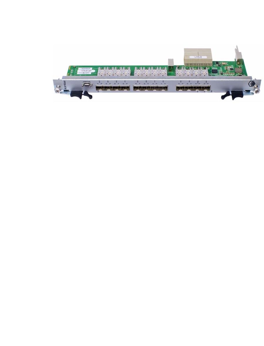
Page 10-228
User Manual
Continuous Computing Corporation
FlexPacket ATCA PP50 Packet Processor
Preliminary
10.1 Standard RTM
The standard RTM functions as a basic RTM. No bypass functionality is available.
10.1.1 Standard RTM Features
PP50 RTMs provide the following features:
● Ten GE 1000BaseT copper port
● Two standard 10GE SFP+ ports
10.1.2 Specifications and Features
• All AdvancedTCA components conform to the AdvancedTCA specification:
PICMG3.0 R2.0
• The RTM-COP50 RTM is hot swappable.
10.1.2.1 General
• Ten 1000BaseT gigabit Ethernet ports over RJ45 terminating SerDes lanes from
the front blade.
• Two 10GE SFP+ ports terminating XAUI lanes across their respective PHYs.
10.1.2.2 Mechanical
• The COP50 base board may be used as a single wide RTM in accordance with
PICMG 3.0.
• Dual RJ45 connectors are magnetic free but contain LEDs.
• Contains a serial port with RS232 transceiver and microDB9 connector.
• RTM back panel has a metal shield covering RJ45 connectors, relay circuitry
and secondary side of magnetics to minimize EMC/EMI interference.
Figure 10-1: Standard RTM

Page 10-229
Preliminary CC06786-11B
Confidential and Proprietary
Rear Transition Modules
1
4ABAB
Preliminary
10.1.2.3 Power
• The power supply supports hot swap.
• RTM contains a compliant ESD strip circuit.
10.1.2.4 Management
The management interface to the IPMC includes:
• A FRU EEPROM.
• Standard LEDs and a handle switch.
• FlexConsole serial port.
• MDIO connection to the 10GE PHY(s).
• Interrupt connection back to the IPMC for changes in SFP status.
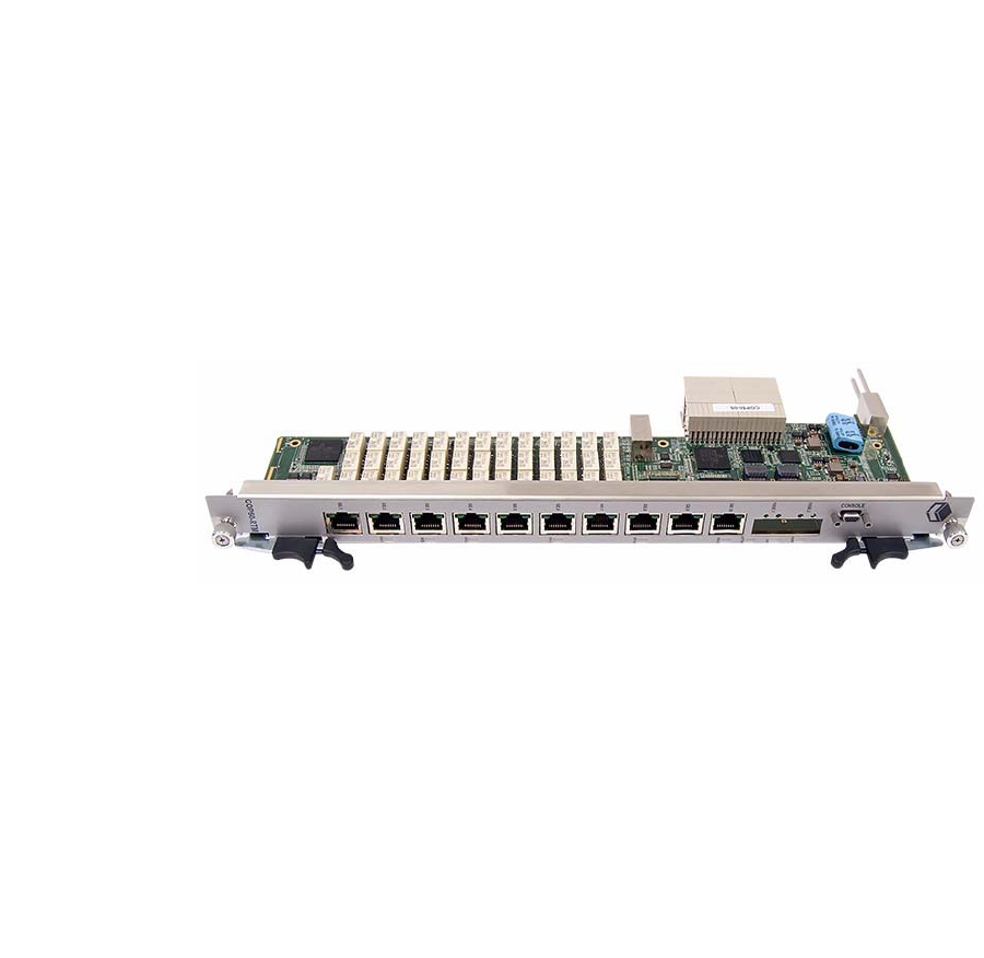
Page 10-230
User Manual
Continuous Computing Corporation
FlexPacket ATCA PP50 Packet Processor
Preliminary
10.2 COP50 RTM
The COP50 offers the functions of the standard RTM and additional bypass func-
tionality. Using a combination of hardware bypass technology and a management
processor, the COP50 monitors the DPI platform for failures. In normal operation,
traffic passes into the RTM and through to the DPI processor. In the event of failure
detection, including complete power outage, the product diverts traffic around the
device, thereby avoiding network outages. With this bypass capability inside the
ATCA system, external bypass solutions are not needed. The standard RTM offers
no such capability. See the following sections for more details.
10.2.1 COP50 Features
PP50 RTMs provide the following features:
● Ten GE 1000BaseT copper port
● Two standard 10GE SFP+ ports
● Live and power loss bypass protection of individual pairs of copper ports
(COP50).
Figure 10-2: COP50 RTM

Page 10-231
Preliminary CC06786-11B
Confidential and Proprietary
Rear Transition Modules
1
4ABAB
Preliminary
10.2.2 Important COP50 Terms Definitions
Consistent usage of these terms to describe the configuration and the current opera-
tional state of the RTM’s ports is important in any discussion of the COP50.
Port-Pair: A pair of adjacent ports (0, 1) (2, 3) (4, 5) (6, 7) and (8, 9) that have the
capability to be connected together such that the external-facing ports are connected
in a straight-through connection.
Bypass State: the state where a port-pair’s external ports are connected together,
preventing any packets from reaching the PP50.
Inline State: the state where a port-pair’s ports are connected into the PP50, allow-
ing processing of packets.
Direct Mode: A port-pair configuration where the ports are always in the Inline
State and will never switch to Bypass State.
Flowthrough Mode: A port-pair configuration where the ports are always in the
Bypass State and will never switch to Inline state.
Protected Mode: A port-pair configuration in which the ports will stay in the Inline
State as long as heartbeats are received and power is present, but will otherwise
automatically switch to Bypass State.
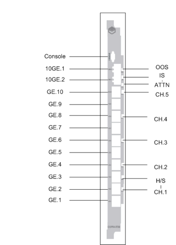
Page 10-232
User Manual
Continuous Computing Corporation
FlexPacket ATCA PP50 Packet Processor
Preliminary
10.2.3 COP50 RTM Overview
Figure 10-3: COP50 Front View
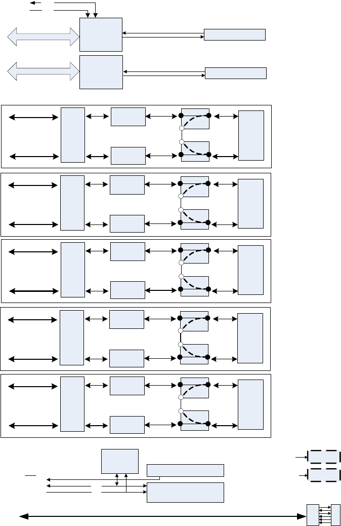
Page 10-233
Preliminary CC06786-11B
Confidential and Proprietary
Rear Transition Modules
1
4ABAB
Preliminary
Figure 10-4: RTM-COP50 Block Diagram
I2C GPIO
CPLD
SDA
SCL
SFP
10GE PHY
XAUI
I2C
FRU
EEPROM
ZONE 3 RTM IFC
RS232
CONSOLE
INT
10GE PHY
SFP
bypass
std
std
Dual
RJ45
GE
magnetic
GE
magnetic
Dual
PHY
serdes
10 00 Bas e T
XAUI
port9
port8
ch ann el5
10GE 0
10GE 1
bypass
std
std
Dual
RJ45
GE
magnetic
GE
magnetic
Dual
PHY
serdes
1000BaseT
port7
port6
chan ne l4
bypass
std
std
Dual
RJ45
GE
magnetic
GE
magnetic
Dual
PHY
serdes
1 000 Ba s eT
port5
port4
ch an ne l3
bypass
std
std
Dual
RJ45
GE
magnetic
GE
magnetic
Dual
PHY
serdes
10 00B as e T
port3
port2
channel2
bypass
std
std
Dual
RJ45
GE
magnetic
GE
magnetic
Dual
PHY
serdes
1000BaseT
port1
port0
chan ne l1
MDIO
MDC
MDIO
Channel
state LED
CPLD
Port LEDs
GE PHY

Page 10-234
User Manual
Continuous Computing Corporation
FlexPacket ATCA PP50 Packet Processor
Preliminary
The block diagram above presents 5 distinct pairs of copper GE ports creating a pro-
tected channel where one ingress GE port can be switched to its associated egress
GE port in the event of a software or power failure. Relays are used to mechanically
connect adjacent ports.
Both 10GE SFP+ ports operate in standard mode and do not receive any protection.
10.2.3.1 Bypass protection
Control of the bypass protection resides within the front blade IPMC complex. At
bootup or by management command, software configures each port-pair to enable
protection or not. During normal operation, a daemon running on the IPMC acts as
a server to allow management software running somewhere else in the system (on
the XLRs or an external blade) to kick the RTM CPLD watchdog at regular interval
to confirm its sanity.
Upon failure of either watchdog timer or power, the CPLD initiates a protection
switch on all port-pairs such provisioned. Relays are simply reset in the bypass
position connecting ingress and egress copper port together as a line loopback.
10.2.4 COP50 Specifications and Features
• All AdvancedTCA components conform to the AdvancedTCA specification:
PICMG3.0 R2.0
• The RTM-COP50 RTM is hot swappable.
10.2.4.1 General
• Ten 1000BaseT gigabit Ethernet ports over RJ45 terminating SerDes lanes from
the front blade.
• Two 10GE SFP+ ports terminating XAUI lanes across their respective PHYs.
• Electrical bypass protection of individual 1000BaseT GE port-pairs [pair of GE
ports].
10.2.4.2 Mechanical
• The COP50 base board may be used as a single wide RTM in accordance with
PICMG 3.0.
• Dual RJ45 connectors are magnetic free but contain LEDs.
• Contains a serial port with RS232 transceiver and microDB9 connector.
• RTM back panel
• has a metal shield covering RJ45 connectors, relay circuitry and secondary side
of magnetics to minimize EMC/EMI interference.
10.2.4.3 Power
• The power supply supports hot swap.

Page 10-235
Preliminary CC06786-11B
Confidential and Proprietary
Rear Transition Modules
1
4ABAB
Preliminary
• Power supply includes a SuperCap capable of powering the necessary circuitry
in the event of a power failure. It contains enough energy to address the worst
case scenario over current and voltage drop over time.
• Power supply includes an aggregate power good signal fed to both front card
and CPLD.
• Devices not essential to the bypass protection circuit are power by a distinct
3V3 rail. 10GE phy, SFP cages, and unrelated logic fit this definition.
• RTM contains a compliant ESD strip circuit.
10.2.4.4 Management
The management interface to the IPMC includes:
• A FRU EEPROM.
• Standard LEDs and a handle switch.
• FlexConsole serial port.
• CPLD registers including protection control.
• Additional GPIOs under i2c control.
• MDIO connection to the 10GE PHY(s).
• Interrupt connection back to the IPMC for changes in SFP status.
Board includes a single voltage rail/low power CPLD.
• Register-based timer part of the CPLD to set the watchdog period. Range is
from 0.4 sec to 50.0 sec in 0.2sec increments (8-bit resolution).
• Powerup default value is 0 (watchdog inactive).
• When the watchdog timeout is set to 0, the CPLD will neither set nor reset any
relay coils. (i.e., since the default timeout is 0, on powerup the CPLD will NOT
modify the relay states until so commanded by the management software.
• CPLD has an i2c slave interface to the IPMC complex.
• CPLD provides individual protection of each port-pair. Locking registers select
between protected and non-protected mode preventing erroneous software
operation.
• CPLD triggers the bypass of the selected channels upon detection of loss of
power or a missed software watchdog event.
• CPLD can be upgraded via software from the IPMC.
• CPLD uses its internal oscillator for all operation instead of relying on external
circuitry.
• CPLD autonomously set/resets the channel relays during normal operation at a
regular internal. (i.e., similar to DRAM refresh, the CPLD periodically ensures
that the relays do in fact reflect the internal state).
CPLD displays the protection status of each channel through a dedicated LED:

Page 10-236
User Manual
Continuous Computing Corporation
FlexPacket ATCA PP50 Packet Processor
Preliminary
• Dark – port-pair is in Direct mode.
• Green – port-pair is in Protected mode, Inline state.
• Red – port-pair is in Protected mode, Bypass state.
10.2.4.5 Bypass protection
• Bypass protection circuit resets individual relay coil consecutively to minimize
current surge from the superCap upon detection of a failure.
• Bypass protection circuit resets all selected port within 250ms upon detection of
a failure.
10.2.4.6 IPMC Firmware
• IPMC software enables/disables protection of each individual port-pair as part
of the port configuration. The ability to elect protection on a given channel is
software configurable, no dip switch, or mechanical header involved.
• When requested by external management software, IPMC software kicks the
RTM watchdog by writing a strobe command to the CPLD.
• Board logic allows for individual port-pair control (5 distinct timers).
• IPMC softrt-pair modes, and sending watchdog kick event.
10.2.5 Installation and Usage
10.2.5.1 Initial Installation
When an RTM comes out of the shipping box, there is no way to know what state
the relays are in. Connecting two incoming cables to a pair of ports that are
bypassed could create network loops if those cables were intended to be direct
connections without bypass protection. Because of this the following cases should
be considered.
• All ports are being used as Protected port pairs. In this case, cables can be
connected to the RTM at any time because an unexpected RTM configuration
can’t create network loops. However, if minimum down time on each external
connection is desired, it is still best to make sure the RTM is in a known (all
ports bypassed) state before connecting them to the RTM.
Note: The port-pair LEDs are only valid when the Blue Hot-Swap LED is
OFF (for example when the RTM is powered). Any time the Blue
Hot-Swap LED is on or blinking, the RTM power is either off or
transitioning. The relays will maintain their last programmed mode
(for Direct or Flowthrough ports) or will revert to Bypass state (for
Protected ports). But the LEDs cannot reflect that state until the
RTM is powered and cop50d is actively managing the RTM.

Page 10-237
Preliminary CC06786-11B
Confidential and Proprietary
Rear Transition Modules
1
4ABAB
Preliminary
• Some or all ports are being used as Direct connections without bypass
protection. In this case, the RTM must be powered and properly configured
under software control before attaching the external cables or else ports could
be inadvertently connected.
10.2.5.2 PP50 IPMC Bootup and the COP50
This section describes the PP50 IPMC boot up as it relates to the COP50.
1. fswd is booted, reads its configuration file, and applies its settings to the Fabric
Switch.
2. If the KV variable “bypasscfg” exists, then the COP50 Control Daemon
(cop50d) is started. If this variable does not exist, cop50d will not be started
and there will be no way to control the port-pair state of the COP50 RTM.
The KV variable “bypasscfg” controls how cop50d starts up. If bypasscfg
contains "on" then the COP50 Control Daemon (cop50d) is started with no
default configuration and will await a configuration command from external
management via the API.
If bypasscfg contains "MMMMM TIMEOUT" (mode configuration and timeout
in milliseconds) then cop50d will be started with that initial configuration but
using the default port for TCP/UDP communications.
If bypasscfg contains "MMMMM TIMEOUT PORT" (mode, timeout in
milliseconds, TCP/UDP port) then cop50d will be started with that initial
configuration.
If bypasscfg does not exist or has any format not matching the above examples,
then cop50d will not be started and there will be no way to control the port-pair
state of the COP50 RTM.
3. cop50d confirms the presence and compatibility of the COP50-RTM CPLD on
the RTM I2C bus by reading the CPLD version register (syslog messages will be
created if an unusable CPLD revision is found.).
4. cop50d attempts to read the initial configuration from KV variable “bypasscfg”.
If the variable exists and is parsable, the specified states are configured
immediately. If the variable is not correctly formatted or does not exist, no
configuration action is taken.
5. cop50d will then listen for and act on UDP and TCP packets containing
commands and/or heartbeat strobes, while periodically monitoring RTM
presence.
Note: The default Fabric Switch configuration is set for generic PP50
RTMs. To work with COP50s the VLAN configuration must be
changed. See Section8.2, "Fabric Switch Management" for
instructions about configuring

Page 10-238
User Manual
Continuous Computing Corporation
FlexPacket ATCA PP50 Packet Processor
Preliminary
10.2.5.3 RTM Insertion
When COP50 RTM Presence is detected via a successful read of the Version register
in the CPLD, the cop50d daemon copies its internal mirror of the desired CPLD
state into the CPLD and sets its internal RTM Present flag. The state mirror consists
of the {Direct, Flowthrough, Protected} mode settings for each port and the watch-
dog timeout. Any ports configured for Direct or Flowthrough mode are
immediately switched to the corresponding state (Inline or Bypass). Ports config-
ured for Protected mode do not change state until an Arm command is received.
10.2.5.4 Upgrading the COP50 RTM CPLD
To upgrade the COP50’s CPLD, run the jbi command in the CNode Linux CLI. The
upgrade takes at least 9 minutes. This tool will erase, program, and verify the
upgrade.
Caution: If you have any problems executing the command, run the command
again. DO NOT turn the RTM off unless running the command fails on several
attempts.
Two variations of the command may be used:
a) jbi -aPROGRAM -ddo_real_time_isp=1 /etc/cpld/cop50-cpld.jbc
or
b) jbi -aPROGRAM /etc/cpld/cop50-cpld.jbc
We suggest you use the first command, the Altera PDF real-time ISP allows you to
program a MAX II device while the device is still in operation. The software only
replaces the software when the device is power cycled (powering down and back
up again). This feature enables you to perform in-field updates to the MAX II device
at any time without affecting the operation of the whole system.
Note: Before running jbi to upgrade the COP50 RTM CPLD, run the
”killall ipmcd” command to terminate the ipmcd daemon.
Note: After successfully upgrading the COP50 RTM CPLD, run “reboot”
to restart CNode.

Page 10-239
Preliminary CC06786-11B
Confidential and Proprietary
Rear Transition Modules
1
4ABAB
Preliminary
10.2.5.5 RTM Removal
When the RTM is removed, the cop50d daemon detects its absence by three consec-
utive NAK’d I2C transactions to the RTM CPLD. It clears its internal RTM Present
flag indicating the RTM is not present and will respond to watchdog strobes with
that information if so requested. The daemon continues to run and poll for RTM
insertion. When the CPLD is again available, the daemon will proceed as in RTM
Insertion above.
10.2.5.6 Auto-Arm versus Managed Re-Arming
This API supports two modes of recovering from a watchdog timeout.
Some system designers may prefer failfast operation, where once a port misses
enough strobe heartbeats that it goes to bypass state, it can only be put back into
direct state by a purposeful action from the management system. Even if heartbeats
start flowing again, the port-pair will not automatically resume direct state. For this
type of operation, use the “Strobe” command to strobe the watchdogs. Then have
some other management thread periodically use the Query Request command to
verify that all desired ports are still in Direct state. If not, this thread will use the
Arm Channel(s) command to rearm the port-pairs after appropriate action has been
taken to ensure the packet processing threads are running and are prepared to send
Strobe commands again.
Others may prefer that a port-pair automatically resume direct state as soon as the
heartbeats resume flowing. To support this method, simply use the Arm Channel
command in place of the Strobe command to strobe the watchdogs. The Arm com-
mand resets the watchdog on the specified channel(s) and also forces state to direct
mode. This style works well with using the bypasscfg KV variable to start up the
bypass control daemon with a desired configuration; then no separate management
entity is needed.
10.2.5.7 Software Specifications
10.2.5.7.1 KV variable format
The bypasscfg KV variable is formatted as follows:
MMMMM TIMEOUT PORT
where each M represents one port pair and is “P” for protected mode, “F” for flow
through, and “D” for direct mode. PORT is the UDP and TCP port used by cop50d
for commands and watchdog strobe requests. TIMEOUT is the CPLD timeout value
in milliseconds.
Note: During a graceful shutdown, no particular action is taken when
RTM shutdown request is received. This case is treated the same as
when an RTM is removed without a request.

Page 10-240
User Manual
Continuous Computing Corporation
FlexPacket ATCA PP50 Packet Processor
Preliminary
Any value of timeout less than the resolution of the CPLD (0.2seconds) will be
treated as a value of 200msec. Other values will be rounded to the nearest 200msec
increment. A value of timeout greater than the maximum CPLD count (50.0 sec-
onds) will be treated as 50.0 seconds.
After reading and parsing the bypasscfg variable, the cop50d emits a syslog mes-
sage indicating the parsed values it is using for MMMMM, PORT, and TIMEOUT.
If bypasscfg is not found in KV, the UDP port defaults to 9725 and the cop50 dae-
mon starts in an unconfigured state where the CPLD will not be sent any
commands.
10.2.5.7.2 State Model
The cop50d daemon’s internal state model consists of:
The valid bit is set if a valid bypasscfg variable is found at startup, or any time a
valid Configure UDP/TCP message is received.
Until the valid bit is set, the cop50d daemon will not configure the RTM CPLD’s reg-
isters. When this is the case, the CPLD will not switch the relays in either direction.
Any time the RTM transitions from nonpresent to present, the cop50d checks the
internal model’s valid bit, and if valid, copies the internal state into the CPLD.
10.2.5.7.3 Network Transport
COP50D accepts commands over both UDP and TCP connections. All commands
and responses are text-based so that netcat, telnet, or python can easily be used to
communicate with the daemon.
In the case of UDP transport, each incoming UDP packet is assumed to contain
exactly one command. The command is passed to the command parser for han-
dling, and the response message (if any) is returned as a single UDP packet to the
originating IP address/port.
Figure 10-5: cop50d daemon’s Internal State Model
State Value Description
valid 1 bit indicates a valid config has been set via KV or
network
mmmmm 5 elements indicates the direct/flowthrough/protected mode for
each port pair
tttt 16 bits stores the watchdog timeout value in msec
Page 10-241
Preliminary CC06786-11B
Confidential and Proprietary
Rear Transition Modules
1
4ABAB
Preliminary
In the case of TCP transport, data is read from the socket until a newline is received.
At that point the command is passed to the parser for handling. The response mes-
sage, if any, is sent back over the socket and the socket is left open awaiting further
commands. All response messages are a single line of text ending with a newline
except for the “?” command which returns complete CLI usage.
It is recommended that UDP transport be used for Watchdog Strobe commands so
that the loss of one strobe won’t incur possible delays from TCP stream retry timers,
possibly backing up subsequent heartbeats.
UDP or TCP transport may be used for configuration commands, though it’s usu-
ally easier to use TCP where delivery is assured and the response comes back
synchronously on the socket than to use UDP and have to implement your own
retry mechanism and response timeout.
10.2.5.7.4 Configuration message format
c MMMMM TIMEOUT
‘c’ is a literal ‘c’ for the configure command
MMMMM is a list of port configurations, ‘D’ for direct, ‘F’ for flowthrough, and ‘P’
for protected. Port-pairs are listed in numerical order (0, 1, 2, 3, 4) so this command
will extend easily to future boards with higher port-pair counts.
Note that configuring a port for Protected mode does NOT automatically switch it
to inline state. You must also Arm the port to make the state change.
TIMEOUT is the port timeout in milliseconds
cop50d confirms receipt of the configuration message by replying with:
OK - Settings applied to COP50 CPLD
DEFER - Settings saved, will be applied when RTM is present
ERROR message - An error occurred (such as invalid arguments)
A valid configuration command will always succeed even if the RTM is not cur-
rently present; the “DEFER” message will be returned and the daemon will cache
the requested state and apply it to the RTM when present.

Page 10-242
User Manual
Continuous Computing Corporation
FlexPacket ATCA PP50 Packet Processor
Preliminary
10.2.5.7.5 Strobe Watchdog(s) request
Strobing a channel resets the watchdog timer for that channel to the currently-con-
figured timeout value. The strobe command does not have any direct effect on the
channel’s state. That is, if a protected port’s watchdog has expired and the port is in
Bypass state, simply strobing the watchdog will not reset the port to Inline. (Com-
pare with the “Arm” command.)
s CCCCC
‘s’ is a literal ‘s’ for the strobe command
CCCCC is a field of flags indicating whether to strobe each port. 1 indicates strobe, 0
indicates to skip that port. Port-pairs are listed in numerical order 0 though 4.
CCCCC may also be replaced with “all” to strobe all ports configured for Protected
mode.
Unless otherwise configured, COP50D will respond with one of the following
OK - Settings applied to COP50 CPLD
UNAVAIL - RTM is not present/powered, command had no effect
ERROR message - An error occurred (such as invalid arguments)
COP50D may be configured whether to respond or not to heartbeat requests over
the UDP channel. COP50D will always send a response to TCP requests.
10.2.5.7.6 Arm Port-Pair(s) request
Arming a Protected port-pair resets the watchdog timer for that port-pair and
switches the port states to Inline. If a port is found to have expired and switched to
bypass state, this command is used to re-enable it for inline use.
a AAAAA
‘a’ is a literal ‘a’ for the arm command
AAAAA is a field of flags for whether to arm each port. 1 indicates arm, 0 indicates
to skip that port. Port-pairs are listed in numerical order 0 through 4. AAAAA may
also be replaced with “all” to arm all ports configured for Protected mode.
Unless otherwise configured, COP50D will respond with one of the following
OK - Settings applied to COP50 CPLD
UNAVAIL - RTM is not present/powered, command had no effect
ERROR message - An error occurred (such as invalid arguments)
Note: Don't strobe the watchdog at intervals greater than 150ms. This will
let the COP50 consume many CPU resources. Three to six strobes
per timeout slice is enough.
Page 10-243
Preliminary CC06786-11B
Confidential and Proprietary
Rear Transition Modules
1
4ABAB
Preliminary
COP50D may be configured whether to respond or not to arm requests over UDP.
COP50D will always send a response to TCP requests.
10.2.5.7.7 Query Request
To query the current configuration and state of the daemon and CPLD, send ‘q’.
COP50D will respond with:
MMMMM SSSSS TIMEOUT
MMMMM = Channel mode for each channel in order from 0 though 4
-- = Configuration not valid (no config command received yet)
P = Protected mode
D = Direct mode
F = Flowthrough mode
SSSSS = Channel state for each channel 0 through 4:
B = bypass state
I = Inline state
-- = RTM unavailable/unpowered
TIMEOUT = configured timeout in milliseconds
10.2.5.7.8 Echo UDP Strobe/Arm commands
E selects whether UDP commands will cause a UDP reply packet or not. 1 = send a
response. 0 = no response. Note that if ‘echo’ is turned off, the query command
isn’t useful over UDP. Default is to NOT respond over UDP.
e E
E = 1 (send response to UDP commands);
0 for silent (no response to UDP commands)
10.2.5.8 COP50 Usage Example
1. Ensure IPMC has firmware that includes cop50d functionality.
2. Log in to IPMC as root.
3. Type “cnodekv bypasscfg on” to enable cop50d on next reboot. Type “cop50d”
to start the daemon now.
4. Type “telnet localhost 9725” to connect to the daemon
5. Type “c PPPFD 20000” to set three port-pairs to Protected mode, one to
Flowthrough and one to Direct.

Page 10-244
User Manual
Continuous Computing Corporation
FlexPacket ATCA PP50 Packet Processor
Preliminary
6. Arm the ports by typing “a all”
7. Check the RTM LEDs (within 20 seconds) to see proper indications.
8. Every 10 seconds or so, type “s all” to strobe the watchdogs and keep the ports
in Inline state.
9. Check the status with “q”
10. Do not send any arm commands for more than 20 seconds. You can then
confirm port-pairs 0-2 are in Bypass state by cross-checking LED state, “q”
command output, and link state from fswd for the RTM 1G ports.
11. Use “Control-] <enter> e <enter>” to exit IPMC telnet.
Note: you can also use telnet from any other networked PC by connecting to port
9725 on the PP50 IPMC’s IP address.

Page 11-245
CC06786-11B
Confidential and Proprietary
11
Preliminary
11Firmware Upgrades
This chapter illustrates how to upgrade the PP50’s firmware. Your command line
input and output may vary depending on variables such as software and hardware
versions and network environment.
11.1 CPLD Upgrade
CPLD firmware can be upgraded using a Linux command line utility run from the
IPMC 405 processor. The XLR0, XLR1, and the LED CPLD all can be programmed
using this utility.
To upgrade a CPLD:
1. Login to the IPMC PPC405 Linux Shell. The default login is root user with no pass-
word (blank).
2. Download the CPLD file to the directory
3. Run cpldupgrade
Note: After version v2.3.2b02, users do not need to upgrade the XLR/
LED CPLD manually. The system will upgrade them
automatically. When the IPMC starts, it will check the CPLD
release version with the key value of CPLD version, if they do not
match, the CPLD will be upgraded automatically.
Note: The JTAG CPLD cannot be upgraded through software. It only can
be upgraded using a Xilinx cable.
cpldupgrade <type> <file>

Page 11-246
User Manual
Continuous Computing Corporation
FlexPacket ATCA PP50 Packet Processor
Preliminary
where:
• type = 0 for XLR0 CPLD
• type = 1 for XLR1 CPLD
• type = 2 for LED CPLD
•<file> stands for the CPLD firmware in xsvf format
11.1.1 CPLD Upgrade Examples
Use the examples below for reference.
Another example of the command only
Upgrading the CPLD on both XLRs
Upgrading the LED CPLD
root@cnode-pp50:~ cpldupgrade 0 razacpld_test.xsvf
Starting CPLD programming...
CPLD number is 0
XSVF Player v5.01, Xilinx, Inc.
XSVF file = razacpld_test.xsvf
SUCCESS - Completed XSVF execution.
Execution Time = 2.310 seconds
Please reset system after the upgrade is finished, to make new CPLD take effect.
cpldupgrade 0 pp50-xlr-cpld-v0x08.xsvf
cpldupgrade 1 pp50-xlr-cpld-v0x08.xsvf
cpldupgrade 2 pp50-p2r2-led-cpld-v0x04.xsvf

Page 11-247
CC06786-11B
Confidential and Proprietary
Firmware Upgrades
1
4ABAB
Preliminary
11.2 XLR bootloader Upgrade
This section describes how to upgrade the XLR0 and XLR1 bootloaders.
11.2.1 Get Image File
11.2.1.1 Upgrade Boot Flash Via Network
1. Assume the new bootloader image file (flash.bin) is located at tftp server
10.4.69.69:/tftpboot/.
2. Connect both XLRs' gmac0 to the network via a cable before XLR bootup, then
boot the XLR and run the command below on the bootloader's prompt.
3. Run command "ifconfig -i gmac0 -a 10.4.69.11 -g 10.4.0.254 -n 255.255.255.0."
The outputs will be as follows.
11.2.1.2 Get Bootloader Image File from TFTP Server
Run command "tftpc -s 10.4.69.69 -f flash.bin". The output will be as follows.
11.2.2 Loading Image Files
The PP50 offers two methods for upgrading XLR firmware.
•Ping-Pong Upgrade Method
•Factory Golden Upgrade Method
Both ensure the system remains operable. The choice is one of customer conve-
nience and custom.
Set IP address for gmac0
PP50-0 $ ifconfig -i gmac0 -a 10.4.69.11 -g 10.4.0.254 -n 255.255.255.0
ipaddr: 10.4.69.11
gateway: 10.4.0.254
netmask: 255.255.255.0
PP50-0 $ Starting Network interface "gmac0"
PP50-0 $ tftpc -s 10.4.69.69 -f flash.bin
Downloading [flash.bin].
Server IP : 10.4.69.69
tftpc stall, check network setup
Bytes downloaded: 786432
tftpc: download done. size = 786432 @ address 0x8c396530
PP50-0 $
Note: The XLR always copies the bootloader it is running to flash, so there is no
problem with upgrading the current active bank.

Page 11-248
User Manual
Continuous Computing Corporation
FlexPacket ATCA PP50 Packet Processor
Preliminary
With the ping-pong method, the inactive bank is upgraded. That way, the active
bank contains the proven revision (N), and the new version (N.1) stays on the oppo-
site bank until proven operable.
If revision N.1 doesn't work after it’s loaded, reset to version N on the other bank to
restore system operation. See Section11.2.2.1, "Ping-Pong Upgrade Method" for
details.
In the factory golden strategy, new firmware is loaded into bank A and the original
firmware is left in bank B. Thus, bank A gets the firmware with new features, but
the original firmware is still in ank B.
If the upgrade of bank A is unsuccessful, boot off bank B and use that to reload Bank
A with a firmware image that is known to be working. See Section11.2.2.2, "Factory
Golden Upgrade Method" for details.
11.2.2.1 Ping-Pong Upgrade Method
1. Use bk_update to write the new image N.1 into the inactive flash bank. Output
will be as follows.
2. At the xlr bootloader prompt, run the “rollboot” command to boot from the
opposite bank.
PP50-0 $ bk_update
Begin to update boot flash(cs3), iobase: 0xb8000000.
Writing flash.bin address: 0x8c396530 Size: 917504 crc 0x1228
Erasing 0xb8000000...
Erasing 0xb8020000...
Copying from 0x8c476530 to 0xb80e0000...
Done.
Verifying...Done.
PP50-0 $
Page 11-249
CC06786-11B
Confidential and Proprietary
Firmware Upgrades
1
4ABAB
Preliminary
3. If the new boot fails, use the IPMC debug command to switch to original bank.
Figure 11-1: Ping-Pong Upgrade Flow Diagram
For details regarding kv keys for upgrading flash banks see Section7.4, "Key Value
(KV) Database" , specifically the kv key sX_next_bank (X: 0 or 1) .
11.2.2.2 Factory Golden Upgrade Method
1. Use boot_update to overwrite the image in the active flash bank A. Output will
be as follows.
PP50-0 $ boot_update
Begin to update boot flash(cs0), iobase: 0xbc000000.
Writing flash.bin address: 0x8c396530 Size: 917504 crc 0x1228
Erasing 0xbc000000...
Erasing 0xbc020000...
Copying from 0x8c476530 to 0xbc0e0000...
Done.
Verifying...Done.
PP50-0 $
PING-PONG UPGRADE
USES OPPOSITE (INACTIVE)
BANK FOR UPGRADE
USING bk_update, LOAD
NEW REV (N.1) INTO
INACTIVE FLASH BANK
SET KV VARIABLE
sX_next_bank TO BOOT
FROM PREVIOUS BANK
NEW BOOT
OKAY?
END
REBOOT
SET KV VARIABLE
sX_next_bank TO BOOT
FROM
OPPOSITE BANK
YES
NO

Page 11-250
User Manual
Continuous Computing Corporation
FlexPacket ATCA PP50 Packet Processor
Preliminary
2. Reboot without changing boot banks. Output will be as follows.
3. If the upgrade fails, use the KV boot bank variable to boot from the Factory
Golden image, Bank B.
4. Once booted from Bank B, use bk_update to write a correctly working image
into the primary flash bank. Output will be as follows.
PP50-0 $ reboot
----------------------------------------------------------------
System will be rebooted in about 1 seconds...
Compiled @ 0x0000000046FBA3AF seconds from epoch
Power On reset config = 0x00000000005854EF
================================================================
Continuous Computing
Bootloader 1.3 [Version: pp50-xlr-v2.1.0b00-rc1] for XLR732 on PP50-P2 Board
(type h for help)
================================================================
PP50-0 $
PP50-0 $ bk_update
Begin to update boot flash(cs3), iobase: 0xb8000000.
Writing flash.bin address: 0x8c396530 Size: 917504 crc 0x1228
Erasing 0xb8000000...
Erasing 0xb8020000...
Copying from 0x8c476530 to 0xb80e0000...
Done.
Verifying...Done.
PP50-0 $

Page 11-251
CC06786-11B
Confidential and Proprietary
Firmware Upgrades
1
4ABAB
Preliminary
5. Change the KV back and boot from the now-good image in Bank A.
Figure 11-2: Factory Golden Upgrade Flow Diagram
For details regarding kv keys for upgrading flash banks see Section7.4, "Key Value
(KV) Database" , specifically the kv key sX_next_bank (X: 0 or 1) .
FACTORY GOLDEN UPGRADE
LOADS NEW FIRMWARE IN
ACTIVE BANK A, ORIGINAL
REMAINS IN BANK B
USING boot_update,
OVERWRITE IMAGE IN
ACTIVE FLASH BANK A
SET KV VARIABLE
sX_next_bank TO BOOT
FROM B (GOLDEN)
NEW BOOT
OKAY?
END
RESET KV AND BOOT
FROM PRIMARY (A)
REBOOT WITHOUT
CHANGING
BOOT BANKS
YES
NO
USING bk_update, WRITE
WORKING IMAGE TO
PRIMARY BANK A

Page 11-252
User Manual
Continuous Computing Corporation
FlexPacket ATCA PP50 Packet Processor
Preliminary
11.3 Upgrading the PP50 IPMC
Upgrade the IPMC based on current version.
•Section11.3.1, "Upgrading Versions 2.3.x or Later to a Higher Version" which
provides remote upgrade and u-boot ECC functions.
•Section11.3.2, "Upgrading Versions 2.2.x or Earlier to a Higher Version".
11.3.1 Upgrading Versions 2.3.x or Later to a Higher Version
Assuming you need to upgrade from v2.3.0b00 to v2.3.0b01, follow the instructions
below.
1. Save the non-default fabric switch configuration if there is one.
The key "fswitchCfg" keep the value for the config file, please check if there is
non-default config.
By default, the config file is /etc/fswitchCfg.def
If there is any non-default config, please copy the config to local PC and reserve
it for later usage.
2. Check if the network is not accessible, check and/or configure the interfaces.
For example, to configure eth0.4094
a. To configure the base channel A eth0:
b. Or to configure the base channel B eth0.4094:
3. Download the Firmware and update the Flash
Note: Make sure you are connected to the serial console port from the
PP50.
root@cnode-pp50:~ cnodekv fswitchCfg
root@cnode-pp50:~ cat /etc/fswitchCfg.def
root@cnode-pp50:~ ifconfig eth0 <IP_ADDRESS> netmask <NETMASK>
root@cnode-pp50:~ route add default gw <GATEWAYIP>
root@cnode-pp50:~ ifconfig eth0.4094 <IP_ADDRESS> netmask <NETMASK>
root@cnode-pp50:~ route add default gw <GATEWAYIP>
Note: In order to keep the IP address after upgrade, please configure the
IP_ADDRESS/NETMASK/GATEWAYIP to key-value database.
root@cnode-pp50:~ fwup -f pp50-ipmc-v2.3.0b01/pp50-ipmc-v2.3.0b01.tgz -s
10.3.7.204

Page 11-253
CC06786-11B
Confidential and Proprietary
Firmware Upgrades
1
4ABAB
Preliminary
Or
Or
4. Activate the new release
Then, the IPMC will reboot to the new release.
5. If there is non-default fabric switch config, restore the file
Then, update the file denoted by the key "fswitchCfg", by default, it's /etc/
fswitchCfg.def
Make sure the file is the same as that before upgrade.
Re-configure the fabric switch
11.3.2 Upgrading Versions 2.2.x or Earlier to a Higher Version
1. Pre-upgrade: before upgrading, please follow these steps:
a. Save non-default fabric switch config if necessary
The key "fswitchCfg" keeps the value for the config file, please check if there is non-
default config.
By default, the config file is /etc/fswitchCfg.def
If there is any non-default config, please copy the config to local PC and reserve it
for later usage.
b. Configure IP address information to key-value database
root@cnode-pp50:~ fwup -f http://10.3.7.204/pp50-ipmc-v2.3.0b01/pp50-ipmc-
v2.3.0b01.tgz
root@cnode-pp50:~ fwup -f ftp://10.3.7.204/pp50-ipmc-v2.3.0b01/pp50-ipmc-
v2.3.0b01.tgz
Note: The file should be already put in the right server and directory
root@cnode-pp50:~ rollboot
root@cnode-pp50-nboot:~ cnodekv fswitchCfg
root@cnode-pp50-nboot:~ vi /etc/fswitchCfg.def
root@cnode-pp50-nboot:~ fswitch reload config
root@cnode-pp50:~ cnodekv fswitchCfg
root@cnode-pp50:~ cat /etc/fswitchCfg.def
root@cnode-pp50:~ cnodekv ipaddr 10.4.50.34
root@cnode-pp50:~ cnodekv netmask 255.255.0.0
root@cnode-pp50:~ cnodekv gatewayip 10.4.0.254
root@cnode-pp50:~ cnodekv serverip 10.3.7.204

Page 11-254
User Manual
Continuous Computing Corporation
FlexPacket ATCA PP50 Packet Processor
Preliminary
c. Copy the two images to TFTP server,
» tftpboot/pp50-ipmc-v2.3.0b00 / pp50-ipmc-netboot-v2.3.0b00.ui
» tftpboot/pp50-ipmc-v2.3.0b00/pp50-ipmc-v2.3.0b00.tgz
d. Reboot IPMC and stop at u-boot
press any key to stop the autoboot
2. Upgrade : download the images and update the flash
a. Configure network
b. Check network access in u-boot
If the server ip is alive, the PP50 IPMC is using Base Channel A.
While Base Channel A is used, the IPMC is using eth0 in Linux.
eth0 will use dhcp by default. If you want to use a static IP for eth0, run this
command:
Then continue to step c);
If the server ip is not alive but the network connection works well, the PP50
IPMC is using Base Channel B. Run the following command to change the
bswitch configuration:
While the PP50 IPMC is using the Base Channel B, the IPMC is using eth0.4094
in Linux. Set this interface to be DHCP or static.
The command to set DHCP:
The commands to set static an IP address:
c. Download the netboot image and boot up:
d. Check network access in Linux.
Login to PP50 nboot by user 'root' and check the IP address of interface
eth0 and eth0.4094:
root@cnode-pp50:~ reboot
=> run netup addram
=> ping 10.3.7.204
=> kv cnbsa_proto static
bswitch cfg flood
=> kv cnbsb_proto dhcp
=> kv ipaddr_b 10.4.50.34
=> kv netmask_b 255.255.0.0
=> kv cnbsb_proto static
=> tftp 1000000 pp50-ipmc-v2.3.0b00/pp50-ipmc-netboot-v2.3.0b00.ui; bootm
root@cnode-pp50-nboot:~ ifconfig

Page 11-255
CC06786-11B
Confidential and Proprietary
Firmware Upgrades
1
4ABAB
Preliminary
If neither eth0 nor eth0.4094 is assigned a valid IP address, set static IP
address for the interface.
If the IPMC is using Base Channel A, configure eth0:
If IPMC is using Base Channel B, configure eth0.4094:
e. Download the firmware and update the Flash
The firmware can be put on a HTTP or FTP server.
Or
3. Post-upgrade, if there is non-default fabric switch config:
a. Restore the file
Then, update the file denoted by the key "fswitchCfg",
by default, it's /etc/fswitchCfg.def.
Make sure the file is the same as it was before the upgrade.
b. Reconfigure the fabric switch
11.3.3 Showing, Switching, and Rebooting Boot Banks
Login to IPMC Linux command line then use "showboot" to show boot bank
information.
root@cnode-pp50-nboot:~ ifconfig eth0 10.4.50.34 netmask 255.255.0.0
root@cnode-pp50-nboot:~ route add default gw 10.4.0.254
root@cnode-pp50-nboot:~ ifconfig eth0.4094 10.4.50.34 netmask 255.255.0.0
root@cnode-pp50-nboot:~ route add default gw 10.4.0.254
root@cnode-pp50-nboot:~ fwup -f pp50-ipmc-v2.3.0b00/pp50-ipmc-v2.3.0b00.tgz
-s 10.3.7.204
root@cnode-pp50:~ fwup -f http://10.3.7.204/pp50-ipmc-v2.3.0b00/pp50-ipmc-
v2.3.0b00.tgz
root@cnode-pp50:~ fwup -f ftp://10.3.7.204/pp50-ipmc-v2.3.0b00/pp50-ipmc-
v2.3.0b00.tgz
Note: The Firmware will be updated to two Flash bank automatically, and
system will reboot and run the new release
root@cnode-pp50-nboot:~ cnodekv fswitchCfg
root@cnode-pp50-nboot:~ vi /etc/fswitchCfg.def
root@cnode-pp50-nboot:~ fswitch reload config
root@cnode-pp50:~ showboot
System was booted from bank 1.
The active bank version is: v2.4.0r00
The backup bank version is: v2.3.4b01

Page 11-256
User Manual
Continuous Computing Corporation
FlexPacket ATCA PP50 Packet Processor
Preliminary
Use the "rollboot" command to change boot bank selection, for example:
Use "reboot" command to reboot system in the current bank
root@cnode-pp50:~ rollboot
INFO: check U-Boot on /dev/mtdblock6 success
INFO: check FPGA on /dev/mtdblock7 success
INFO: check kernel on /dev/mtdblock8 success
INFO: check rootfs on /dev/mtdblock9 success
INFO: +++ system will reboot to bank 0 +++

Page 11-257
CC06786-11B
Confidential and Proprietary
Firmware Upgrades
1
4ABAB
Preliminary
11.4 Linux Bootloader Upgrade Tool
Use this tool to upgrade the Linux XLR bootloader.
11.4.1 In WR Linux
Below is example of using the WR Linux upgrade tool.
root@10:/root> upgrade -V
upgrade version 1.2
root@10:/root> upgrade
Usage: upgrade <-a | -s> [options]
Options:
-? Display this usage
-V Display version of this program
-a Use active flash for operation
-s Use backup flash for operation
-b <backup file> Backup flash info to a file
-p <program file> Program file to flash
-v <program file> Verify flash info with a file
for example
For bakckup: upgrade -a -b bootloader.bck
For program: upgrade -s -p bootloader.bin
For verify: upgrade -s -v bootloader.bin
root@10:/root> upgrade -a -b bootloader.bck
Backup flash physical address 0x1c000000 size 0x200000 to file bootloader.bck
... success
root@10:/root> upgrade -s -b bootloader.bcks
Backup flash physical address 0x18000000 size 0x200000 to file bootloader.bcks
... success
root@10:/root> upgrade -s -p bootloader.bin
Erase flash physical address 0x18000000 size 0x120000
Program flash physical address 0x18000000 size 0x120000 with file
bootloader.bin
Verify flash physical address 0x18000000 size 0x120000
Program flash successfully
root@10:/root> upgrade -a -p bootloader.bin
Erase flash physical address 0x1c000000 size 0x120000
Program flash physical address 0x1c000000 size 0x120000 with file
bootloader.bin
Verify flash physical address 0x1c000000 size 0x120000
Program flash successfully
root@10:/root> upgrade -a -v bootloader.bin
Verify flash physical address 0x1c000000 size 0x120000 with file bootloader.bin
... success
root@10:/root> upgrade -s -v bootloader.bin
Verify flash physical address 0x18000000 size 0x120000 with file bootloader.bin
... success
root@10:/root> upgrade -s -v bootloader.bin
root@10:/root> upgrade -s -p ../bootloader.bin
Erase flash physical address 0x18000000 size 0x120000
Program flash physical address 0x18000000 size 0x120000 with file
../bootloader.bin
Verify flash physical address 0x18000000 size 0x120000
Program flash successfully

Page 11-258
User Manual
Continuous Computing Corporation
FlexPacket ATCA PP50 Packet Processor
Preliminary
11.4.2 In RMI Linux
Below is example of using the RMI Linux upgrade tool.
[root@XLR-732 luogr]$ upgrade -?
Usage: upgrade <-a | -s> [options]
Options:
-? Display this usage
-V Display version of this program
-a Use active flash for operation
-s Use backup flash for operation
-b <backup file> Backup flash info to a file
-p <program file> Program file to flash
-v <program file> Verify flash info with a file
for example
For bakckup: upgrade -a -b bootloader.bck
For program: upgrade -s -p bootloader.bin
For verify: upgrade -s -v bootloader.bin
[root@XLR-732 luogr]$ upgrade -V
upgrade version 1.2
[root@XLR-732 luogr]$ upgrade -a -b bootloader.bck
Backup flash physical address 0x1c000000 size 0x200000 to file bootloader.bck
... success
[root@XLR-732 luogr]$ upgrade -s -b bootloader.bcks
Backup flash physical address 0x18000000 size 0x200000 to file bootloader.bcks
... success
[root@XLR-732 luogr]$ upgrade -s -p bootloader.bin
Erase flash physical address 0x18000000 size 0x120000
Program flash physical address 0x18000000 size 0x120000 with file
bootloader.bin
Verify flash physical address 0x18000000 size 0x120000
Program flash successfully
[root@XLR-732 luogr]$ upgrade -a -p bootloader.bin
Erase flash physical address 0x1c000000 size 0x120000
Program flash physical address 0x1c000000 size 0x120000 with file
bootloader.bin
Verify flash physical address 0x1c000000 size 0x120000
Program flash successfully
[root@XLR-732 luogr]$ upgrade -s -v bootloader.bin
Verify flash physical address 0x18000000 size 0x120000 with file bootloader.bin
... success
[root@XLR-732 luogr]$ upgrade -a -v bootloader.bin
Verify flash physical address 0x1c000000 size 0x120000 with file bootloader.bin
... success
[root@XLR-732 luogr]$ upgrade -v bootloader.bin
Please use option <-a | -s> to select the operation flash
[root@XLR-732 luogr]$

Page 11-259
CC06786-11B
Confidential and Proprietary
Firmware Upgrades
1
4ABAB
Preliminary
11.5 XLR Fabric Switch Configuration Utility, Installation
To configure a PP50's Fabric Switch on an XLR:
1. Copy the utility 'fswcmd' and config file 'fswcmd.cfg' to the directory of WR
Linux or RMI Linux is in.
2. Update the 'fswcmd_cfg' with the IPMC IP address info. Note there is a readme
inside the file.
3. Ensure the IPMC IP address is alive by pinging it from WR or RMI Linux.
Note: The 'fswcmd' utility for XLRs can be used on XLRs only; the one
incorporated into the IPMC can be used for the IPMC ONLY.
Note: The 'fswcmd' is compatible with the fabric switch management daemon
'fswd' running in on the IPMC on the condition that the IPMC version is
equal to or greater than v2.2.0b00.
Note: The 'fswcmd' running on the XLR has the same function as the one in
IPMC Linux.
Page 11-260
User Manual
Continuous Computing Corporation
FlexPacket ATCA PP50 Packet Processor
Preliminary
Page 12-261
CC06786-11B
Confidential and Proprietary
12
Preliminary
12Diagnostics and Troubleshooting
Use this chapter to diagnose and troubleshoot PP50s.
12.1 Overview
The PP50 offers two methods (raw CLI and kv keys) for executing three types of tests
(short POST, long POST, and BIST) as shown in the figure below.
Figure 12-1: Diagnostic Tests Tree
Please note the following constraints when running these tests:
• The XLRs BIST function is only supported in RMI Linux with RAM FS, not in
WR Linux.
U-boot (sect. 12.2) KV Keys (sect. 12.3)
XLR IPMC
Short/Long POST BIST (Linux)Short/Long POST BIST (Linux)
IPMC
XLR
LEDs (sect. 12.4)
Diagnosis using . . .

Page 12-262
User Manual
Continuous Computing Corporation
FlexPacket ATCA PP50 Packet Processor
Preliminary
• During POSTs, never reset, power off or power cycle the board. Doing so may
corrupt the firmware.
• The IPMC and Payload BISTs cannot be run at the same time.
12.2 Running Diagnostic Tests from Raw CLI
Use the instructions in this section to run diagnostic tests from the IPMC PPC405’s
u-boot and payload XLRs.
12.2.1 IPMC Raw CLI Diagnostic Commands
1. At IPMC u-boot prompt, type the command diag to view the available test.
Available hardware tests:
Note: Reboot the IPMC after an IPMC BIST test.
Reboot the XLR after an XLR BIST test.
=> diag
Table 12-1: IPMC Raw CLI Diagnostic (Hardware) Tests
Test Test Description Duration
i2c - I2C test instant
rtc - RTC test 1m
memory - Memory test 40-60s
shortmem - Short Memory test instant
nand - NAND test 20-30s
atc210 - ATC210 test instant
bcm5389 - BCM5389 test instant
fswitch - Fabric switch test 1s
fpga - FPGA test instant
frusel - FRUSEL test 1s
hwaddr - HWADDR test instant
ne1617 - NE1617 test instant
pmc8380 - PMC8380 test 1s
rtm - RTM test 1s
tcam - TCAM test 1s

Page 12-263
CC06786-11B
Confidential and Proprietary
Diagnostics and Troubleshooting
1
4ABAB
Preliminary
Use 'diag [<test1> [<test2>...]]' to get more info.
Use 'diag run [<test1> [<test2>...]]' to run tests.
2. Enter the test option to get a description about a specific test.
diag [<test1> [<test2>...]]:
For example:
This test verifies the I2C operation.
3. Use the run option to run a specified test.
diag run [<test1> [<test2> ...]]:
For Example:
4. Use “diag run” to run all the test items
Some items need the fpga function, so you need to “run netup” before “diag run”
After all the items have finished, the test result summary will be listed as follows:
12.2.2 XLR Raw CLI Diagnostic Commands
1. At the XLR bootloader prompt, type the diag command to view the available
tests.
=> diag i2c
i2c - I2C test
=> diag run i2c
POST i2c PASSED
diag run:
=> diag run
POST i2c PASSED
POST rtc Get RTC s since 1.1.1970: 23338344.
POST bcm5389 PASSED
POST fm2112 PASSED
POST fpga
FPGA version :0x8f
Board version:0x01
FPGA Magic :0x7e
PASSED
POST frusel PASSED
POST hwaddr
HW address 0x48, logic slot 0x8
PASSED
POST ne1617 PASSED
POST pmc8380 PASSED
POST rtm PASSED
PP50-0 $ diag

Page 12-264
User Manual
Continuous Computing Corporation
FlexPacket ATCA PP50 Packet Processor
Preliminary
The available hardware tests are listed below.
Use 'diag [<test1> [<test2>...]]' to get more info.
Use 'diag run' to run all test items.
Use 'diag run [<test1> [<test2>...]]' to run specified test item.
Refer to IPMC diagnostic command examples for usage of related test options.
Table 12-2: XLR Raw CLI Diagnostic (Hardware) Tests
Test Test Description Duration
gphy0 - bcm5482 gmac0 test instant
gphy1 - bcm5482 gmac1 test instant
gphy2 - bcm5482 gmac2 test instant
gphy3 - bcm5482 gmac3 test instant
xgphy0 - vsc7280 xgmac0 test instant
xgphy1 - vsc7280 xgmac1 test instant
cpld - cpld test 1s
memshort - short memory test 2s
flashlog - part flash test 5-10s
flashall - full flash test 20-25m
memlong - long memory test 4-5 hours
psram - psram test 45-75s
pcmcia - pcmcia test 1-2s
tcam - tcam register test varies
pft - pseudo fault test varies
sipl - uart 1 sipl channel test 1s

Page 12-265
CC06786-11B
Confidential and Proprietary
Diagnostics and Troubleshooting
1
4ABAB
Preliminary
12.3 Running Diagnostic Tests using KV Settings
This section describes how to run diagnostic tests using a combination of KV keys.
The following table describes the KV keys used for diagnostics.
Generically these are referred to as xx_bootmode and xx_test_mask where xx can be
cn, s0, or s1 for CNode, XLR0 and XLR1 respectively.
The xx_bootmode keys may be assigned the values shown below.
Use the xx_test_mask to map diagnostic items in detail as described below.
The xx_test_mask is a mask of 32 characters which are divided into 3 parts:
• Short POST (character 0 ~ 7)
• Long POST (character 8 ~ 23)
• BIST (character 24 ~ 31)
. For example:
Table 12-3: POST/BIST KV Keys
Component Boot Mode KV Key Test Mask KV key
CNode cn_bootmode cn_test_mask
XLR0 s0_bootmode s0_test_mask
XLR1 s1_bootmode s1_test_mask
Table 12-4: xx_bootmode Settings (xx: cn, s0, s1)
Setting/Value Description
normal normal boot up, only short POST items will run according to
xx_test_mask set
post_only short/long POST items will run according to xx_test_mask set
bist_only short/bist items will run according to xx_test_mask set
post_bist short/long/bist items will run according to xx_test_mask set
Note: The short POST runs in all modes, but all items are controlled by the
test mask key xx_test_mask. If the test mask key is absent, it will be
created with default values to enable all short POST items to be run
automatically while booting.

Page 12-266
User Manual
Continuous Computing Corporation
FlexPacket ATCA PP50 Packet Processor
Preliminary
set key s0_test_mask as “1100xxxx000010xxxxxxxxxxxxxxxxxx”
where:
• 0 disables the test
• 1 enables the test
• x means the test is invalid in this context
Table 12-5: Diagnostic types and test mask string assignment
12.3.1 Running IPMC Diagnostic tests with KV settings
12.3.1.1 IPMC U-boot command for short/long POST tests
Refer to the commands below to run related short/long POST items which are
masked by test mask key string. It is similar to the XLR kv_diag command example.
=> help kv_diag
kv_diag [ -l | --list ] list bootmode and POST test items by kv "cn_test_mask"
and "cn_bootmode"
kv_diag [ -e | --execute ] run POST test items by kv"cn_test_mask" and
"cn_bootmode"
kv_diag [ -r | --result ] show latest POST test result
kv_diag [ -n | --no ] show POST error code and related error string
0 1 2 3 4 5 6 7 8 9 10 11 12 13 14 15 16 17 18 19 20 21 22 23 24 25 26 27 28 29 30 31
Post T ype
Norm al, De faul t
post_only
bist_only
post_bist
Blank cell indicates test is not run.
Note: Short Post Items are always run, even when the boot mode is not set.
BIST
Test Number
Long PostShort Post Items

Page 12-267
CC06786-11B
Confidential and Proprietary
Diagnostics and Troubleshooting
1
4ABAB
Preliminary
12.3.1.2 IPMC Linux utility for POST/BIST tests
1. The utility ux_diag is also located in the rootfs folder “/usr/bin/”, refer to the
usage below for help.
Note in the text above
XX = (cn, s0, s1)
cn means IPMC
s0 means PAYLOAD0
s1 means PAYLOAD1
2. Run command “ux_diag –l cn” to list all available test items for the IPMC
root@cnode-pp50:/etc/cpld ux_diag
usage: ux_diag [-u|--update] [cn|s0|s1]
usage: ux_diag [-l|--list] [cn|s0|s1]
usage: ux_diag [-d|--dump] [cn|s0|s1]
usage: ux_diag [-n|--no] [cn|s0|s1]
usage: ux_diag [-h|--help]
-u update diagnosis configuration using /etc/diag/XX_diag.cfg
-l list all available test items and test states configuration
-d dump the test result and create /var/log/diag/XX_diag.dump
-n list current diagnosis test error number and err string
-h for help
root@cnode-pp50:/ ux_diag -l cn
IPMC bootmode=normal
===========================================================
[TEST_STATE] [MASK_POS] [TEST_TYPE] [TEST_CASE] [TEST_TIME]
n 0 short post i2c <= 1 sec
n 1 short post shortmem <= 15 sec
n 8 long post rtc <= 35 sec
n 9 long post memory <= 40 sec
n 10 long post nand <= 30 sec
n 11 long post bcm5389 <= 1 sec
n 12 long post fswitch <= 2 sec
n 13 long post fpga <= 1 sec
n 14 long post frusel <= 1 sec
n 15 long post hwaddr <= 1 sec
n 16 long post ne1617 <= 1 sec
n 17 long post pmc8380 <= 3 sec
n 18 long post atc210 <= 2 sec
n 19 long post rtm <= 2 sec
n 20 long post tcam <= 2 sec
n 24 bist sfp <= 90 sec
n 25 bist fabricswitch <= 16 min
n 26 bist baseswitch <= 10 sec
root@cnode-pp50:/

Page 12-268
User Manual
Continuous Computing Corporation
FlexPacket ATCA PP50 Packet Processor
Preliminary
3. Run command “ux_diag –d cn” to dump test result
4. Run command “ux_diag –n cn” to list all related test result code description.
root@cnode-pp50:/ ux_diag -d cn
IPMC Diagnostic Test Result
===============================================================================
[MASK_POS] [TEST_TYPE] [TEST_CASE] [TEST_RESULT] [ERROR_CODE] [ERROR_STRING]
0 short post i2c passed 0 test passed
1 short post shortmem passed 0 test passed
Begin to generate cn_diag.dump.
Generate cn_diag.dump OK!
root@cnode-pp50:/
Note: If some test items fail, you can get more details from the log file /
var/log/diag/cn_diag.dump.
root@cnode-pp50:/ ux_diag -n cn
IPMC Diagnosis Error Codes List
==============================
[code] [description]
0 test passed
1 not test
2 invalid test item
3 not response from i2c address
4 date line test error
5 address line test error
6 verify 0x00000000 error
7 verify 0xffffffff error
8 verify 0x55555555 error
9 verify 0xaaaaaaaa error
10 verify 1 shift error
11 verify address self error
12 verify address reverse error
13 verify address peak poke error
14 verify address bit fade error
15 a new second timeout
16 invalid second duration counts
17 month boundary test error
18 read old data error
19 erase old data error
20 write test data error
21 read test data error
22 verify test data error
23 erase test data error
24 restore old data error

Page 12-269
CC06786-11B
Confidential and Proprietary
Diagnostics and Troubleshooting
1
4ABAB
Preliminary
12.3.2 Running XLR Diagnostic Tests with KV settings
XLR diagnostic commands can be run using short/long POST or BIST.
12.3.2.1 XLR Commands for Short/Long POST tests
The kv_diag is was added to allow XLR boot loader CLI tests. Refer to the table
below for its usage and options.
25 bcm5389 page0 test error
26 bcm5389 page10 test error
27 fabric switch ID error
28 fabric register test error
29 fpga register test error
30 fru eeprom test error
31 sel eeprom test error
32 invalid hardware address
33 adress parity verify error
34 ne1617 ambient test error
35 ne1617 XLR0 test error
36 ne1617 XLR1 test error
37 ne1617 fm2112 test error
38 pm8380 GMAC0 test error
39 pm8380 GMAC1 test error
40 rtm is not present
41 rtm eeprom test error
42 tcam sensor 1 test error
43 tcam sensor 2 test error
44 tcam eeprom test error
45 tcam is not present
46 atc210 read error
47 adt7462 verified error
48 max6618 verified error
49 mic184 ambient0 error
50 mic184 ambient1 error
128 frbric switch bist error
129 base switch bist error
130 sfp bist error
root@cnode-pp50:/
Table 12-6: kv_diag Usage and Options
Option Description
–h Shows the usage
–c Shows the current KV set for diagnostic
–v Makes newly set kv values valid (sets them) and displays them. See
the example that follows this table.

Page 12-270
User Manual
Continuous Computing Corporation
FlexPacket ATCA PP50 Packet Processor
Preliminary
Below is an example of how to run the short POST diagnostics on bcm5482 gmac0,
bcm5482 gmac1, or bcm5482 gmac2 in the XLR boot loader CLI:
a. From the XLR boot loader CLI, set the following KV keys:
b. Run command “kv_diag –v” to make the key valid.
c. Run command “kv_diag –c” to ensure the test cases were executed.
d. Run command “kv_diag –e” to execute. See the output below.
e. Run command “kv_diag –r” to show test result. See the output below.
–l Lists the available POST items in XLR boot loader
–e Executes the diagnostic test items currently set in the KV database
–r Shows the latest diagnostic test result
–n Shows the diagnostic test error code
PP50-0 $ kv s0_bootmode normal
PP50-0 $ kv s0_test_mask 11100000000000000000000000000000
PP50-0 $ kv_diag -v
key s0_test_mask value = "11100000000000000000000000000000"
PP50-0 $
PP50-0 $ kv_diag -c
Diagnostic boot mode is set as: s0_bootmode = "normal"
Diagnostic test mask is set as: s0_test_mask =
"11100000000000000000000000000000"
PP50-0 $ kv_diag -e
BCM5482 gmac0 aceess success
BCM5482 gmac1 aceess success
BCM5482 gmac2 aceess success
Long post running in 0 units. Press any key to halt...
POST Diagnostic Test Result
===========================================================
[TEST_CASE] [MASK_POS] [ERROR_CODE] [TEST_RESULT]
gphy0 0 0 Pass
gphy1 1 0 Pass
gphy2 2 0 Pass
PP50-0 $
PP50-0 $ kv_diag -r
POST Diagnostic Test Result
===========================================================
[TEST_CASE] [MASK_POS] [ERROR_CODE] [TEST_RESULT]
gphy0 0 0 Pass
gphy1 1 0 Pass
gphy2 2 0 Pass
Table 12-6: kv_diag Usage and Options

Page 12-271
CC06786-11B
Confidential and Proprietary
Diagnostics and Troubleshooting
1
4ABAB
Preliminary
12.3.2.2 XLR RMI Linux Utility for POST/BIST Tests
1. The ux_diag utility in RMI Linux RAM FS /usr/bin/ for XLRs provides the
tests described below:
2. Run “ux_diag -l s0” to list all available test items for XLR0 as shown below.
[root@Stn000116 jwu]$ ./ux_diag -h
usage: ux_diag [-u|--update] [cn|s0|s1]
usage: ux_diag [-l|--list] [cn|s0|s1]
usage: ux_diag [-d|--dump] [cn|s0|s1]
usage: ux_diag [-n|--no] [cn|s0|s1]
usage: ux_diag [-v]
usage: ux_diag [-h]
-u update diagnosis configuration using /etc/diag/XX_diag.cfg
-l list all available test items and test states configuration
-d dump the test result and create /var/log/XX_diag.dump
-n list current diagnosis test error number and err string
-v display version
-h for help
[root@localhost ~]$ ux_diag -l s0
PAYLOAD0 bootmode=normal
==========================================================================
[TEST_STATE] [MASK_POS] [TEST_TYPE] [TEST_CASE] [TEST_TIME]
n 0 short post bcm5482gmac0 <= 1 sec
n 1 short post bcm5482gmac1 <= 1 sec
n 2 short post bcm5482gmac2 <= 1 sec
n 3 short post bcm5482gmac3 <= 1 sec
n 4 short post vsc7280xgmac0 <= 1 sec
n 5 short post vsc7280xgmac1 <= 1 sec
n 6 short post cpld <= 2 sec
n 7 short post shortmem <= 2 min
n 8 long post shortflash <= 200 sec
n 9 long post fullflash <= 7 min
n 10 long post fullmem <= hours
n 11 long post psram <= 50 sec
n 12 long post pcmcia <= 1 sec
n 13 long post tcamreg <= 1 sec
n 14 long post pseudofault <= 1 sec
n 15 long post uart1test <= 2 sec
n 24 bist tcamentry <= 15 sec
n 25 bist GEtest <= 90 sec
n 26 bist XGEtest <= 45 sec
[root@localhost ~]$
Note: The tcamentry test (test 24 above) with MASK_POS 24 will be
skipped on XLR1 even if it is masked, it can only be executed on
XLR0.

Page 12-272
User Manual
Continuous Computing Corporation
FlexPacket ATCA PP50 Packet Processor
Preliminary
For reader convenience a formal table of the test mentioned above is listed below.
Table 12-7: XLR Diagnostic Tests
XLR Boot Loader s0_test_mask and s1_test_mask
Bit Test Type Test Case Test Duration
0 short POST bcm5482 gmac0 ~ 1 sec
1 short POST bcm5482 gmac1 ~ 1 sec
2 short POST bcm5482 gmac2 ~ 1 sec
3 short POST bcm5482 gmac3 ~ 1 sec
4 short POST vsc7280 xgmac0 ~ 1 sec
5 short POST vsc7280 xgmac1 ~ 1 sec
6short POST cpld ~ 1 sec
7 short POST short memory ~ 2 min
8 long POST part flash ~ 200 sec
9 long POST full flash ~ 7 min
10 long POST long memory ~ hours
11 long POST psram ~ 50 sec
12 long POST pcmcia ~ 1 sec
13 long POST tcam register ~ 1 sec
14 long POST pseudo faulta
a. pseudofault test: Simulates a failed test, sends a fail result to applica-
tion level caller even if all components pass, the test result of this item
will always be “failed” if enabled by sX_test_mask.
~ 1 sec
15 long POST uart 1 sipl channel ~ 1 sec
16~
23
NA NA NA
24 BIST tcamentryb15 sec
25 BIST GEtestc90 sec
26 BIST XGEtestd45 sec

Page 12-273
CC06786-11B
Confidential and Proprietary
Diagnostics and Troubleshooting
1
4ABAB
Preliminary
3. Run command “ux_diag –d s0” to dump the test result
b. tcamentry test: this BIST item includes following subtest cases:
1: 72 bit entry test
2: 144, 288 and 576 entry test
3: TCAM register access test
4: TCAM database read and write
5: Longest prefix match
If all the subtests pass the test passes.
c. GE test: Tests all four XLR GE ports (eth0 through eth3), if any one
GE port fails the test fails.
d. : tests both XLR 10GE ports (eth4, eth5), if either fails the test fails.
[root@localhost ~]$ ux_diag -d s0
PAYLOAD0 Diagnostic Test Result
=============================================================================[MAS
K_POS][TEST_TYPE][TEST_CASE][TEST_RESULT][ERROR_CODE] [ERROR_STRING]
0 short post bcm5482gmac0 passed 0 test ok.
1 short post bcm5482gmac1 passed 0 test ok.
2 short post bcm5482gmac2 passed 0 test ok.
3 short post bcm5482gmac3 passed 0 test ok.
4 short post vsc7280xgmac0 passed 0 test ok.
5 short post vsc7280xgmac1 passed 0 test ok.
6 short post cpld passed 0 test ok.
7 short post shortmem passed 0 test ok.
Begin to generate s0_diag.dump.
Generate s0_diag.dump OK!
[root@localhost ~]$
Note: More details about the test can be found in the log file
/var/log/diag/s0_diag.dump.

Page 12-274
User Manual
Continuous Computing Corporation
FlexPacket ATCA PP50 Packet Processor
Preliminary
4. Run command “ux_diag –n s0” to display all related test result code
descriptions:
[root@localhost /]$ ux_diag -n s0
PAYLOAD0 Diagnosis Error Code List
===================================
[code] [description]
0 test ok.
1 not tested.
2 invalid test item.
3 test failed with illegal parameters.
4 SIPL communication error.
5 memory allocated error.
6 unable to find the test device.
7 unable to read phy id register.
8 unrecognized phy.
9 write/read register error.
10 unkown memory test type error.
11 memory walk one test error.
12 memory walk zero test error.
13 memory write own addr test error.
14 memory write unique addr test error.
15 memory with setting a 8 bit "moving inversions" algorithm as pattern test error.
16 memory with setting a 32 bit "moving inversions" algorithm as pattern test
error.
17 memory with setting modulo X access pattern test error.
18 memory bit fade test error.
19 flash erase operation error.
20 flash write operation error.
21 flash verify error.
22 psram addr space test_1 error.
23 psram addr space test_2 error.
24 psram data line test_1 error.
25 psram data line test_2 error.
26 psram addr line test error.
27 psram access by byte test error.
28 psram access by word test error.
29 pcmcia detect bad compactflash card error.
30 tcam access register error.
127 pseudo fault test error.
128 TCAM bist error.
129 GE port bist error.
130 XGE port bist error.
[root@localhost /]$

Page 12-275
CC06786-11B
Confidential and Proprietary
Diagnostics and Troubleshooting
1
4ABAB
Preliminary
12.4 Indicating XLR’s POST/BIST Status Using LEDs
XLR's POST/BIST status can be determined using the front panel LEDs. This is an
optional feature and requires the presence of an LED action data file:
/etc/PayPostLed.dat
The user needs to create this data file and write LED action entries into it.
• LED1 indicates XLR0's POST/BIST status
• LED2 indicates XLR1's POST/BIST status
On system startup, the ipmcd daemon reads this data file and caches LED actions.
If this data file does not exist or an LED action entry is not in the data file then the
ipmcd will not act upon the LEDs during POST/BIST of the XLRs. On start/stop of
POST/BIST, each XLR sends out an event on Firmware Progress Sensor to the
ipmcd using “Set Sensor Reading and Event Status” command and on receipt of this
command, ipmcd takes action on the LED based on previous cached action. The
LED action data file syntax is shown below.
<payload id> <event data 1> <event data 2> <on | off | short | long>
Where,
Payload id:
0 - XLR0
1 - XLR1
Event data 1:
0x82
Event data 2:
0x0a - start of Short POST
0x1a - finish of Short POST
0x0b - start of Long POST
0x1b - finish of Long POST
0x0c - start of BIST
0x1c - finish of BIST
LED action:
on - LED turn ON
off - LED turn OFF
short - LED Short Blink
long - LED Long Blink

Page 12-276
User Manual
Continuous Computing Corporation
FlexPacket ATCA PP50 Packet Processor
Preliminary
Below are examples of how the parameters may be set.
0 0x82 0x0b long
0 0x82 0x1b off
1 0x82 0x0b short
1 0x82 0x1b off
12.5 Determining Board Build
Determine a board’s build configuration by watching the console output during
CNode boot as shown below.
Loading FPGA Device 0...
........................................
Done.
FPGA[0] Magic 0x7e BoardID 0x0, Revision 0x93
FPGA[0] test start
FPGA[0] test passed
Table 12-8: Determining Board Build by Revision Number
Board
Revision
PCB XLR Switch Power Brick
P2 P2R2 P3 Commer-
cial Industrial FM2112 FM3112 LImited
Feature Full
Feature
00 √√ √ √
01 √√ √ √
02 √√√ √a
a. Some early prototypes revision 02 have a non-full feature power brick.
03 √√√ √
20 √√ √ √
21 √√ √ √
22 √√√√
23 √√ √ √

Page 13-277
CC06786-11B
Confidential and Proprietary
13
Preliminary
13Product Repair and Returns
13.1 Customer Support
A detailed description of our after-sales support and support policies can be found at
www.ccpu.com.
13.2 Warranty
Continuous Computing (CCPU) provides 12-month warranty returns to the factory
for all its hardware products. Customers can buy an extended warranty on the pur-
chased hardware before the original warranty expires. Continuous Computing may
also repair products which are not under warranty on a time and material basis.
A Return Material Authorization (RMA) number is required prior to returning any
product for repairs, upgrades or advance replacements. When returning products to
Continuous Computing, please address the shipment to the attention of RMA Sup-
port, and include the RMA number on the shipping label.
Note: Continuous Computing bears no direct responsibility for any equipment
installation, protective grounding design and construction done for
devices not provided by Continuous Computing, or out of the scope of
designing and planning provided by Continuous Computing. Should any
damage or injury occur due to the customer concerned failing to meet the
requirements of related specifications with regard to construction quality,
construction methods, wiring solutions, materials used, etc., the
consequences should be born by the customer concerned.

Page 13-278
User Manual
Continuous Computing Corporation
FlexPacket ATCA PP50 Packet Processor
Preliminary
13.2.1 RMA Procedure
To return a product for repair first submit an RMA request online at
www.ccpu.com.
If you don't have an account request one from support@ccpu.com.
13.2.2 Non-Warranty Repairs
If your equipment is out of warranty other options are available such as an extended
or fixed price warranty, please contact your sales director for more information.
For non-warranty repairs or services, Continuous Computing will examine the
returned hardware and send a quote for the repairs. Continuous Computing will
not work on the repairs until it gets a purchase order for the repairs. If the customer
chooses not to repair the hardware, they will be responsible for the cost of the repair
estimation and shipping back to the customer.
13.2.3 Shipping
For products under warranty, the customer pays shipping to Continuous Comput-
ing and Continuous Computing pays for return shipment. For products not under
warranty, the customer pays for shipping both ways.
13.2.4 Expedite Option for Repairs
Continuous Computing offers a program to expedite the RMA for an additional
charge for all products whether under warranty or out of warranty. Please contact
your sales director for more information about our Expedite RMA program.

Page 14-279
CC06786-11B
Confidential and Proprietary
14
Preliminary
14Revision History
This chapter lists the revisions made to this document. Please see the Release Notes
for the details of any specific release.
Table 14-1: User Manual Revision History
Revision Date Section: Change
11B 2011/3/11 • Updated for Software release 1.3 Update 3
with the following information:
• Added FIBM overview.
•Section8.2.2, "FIBM Mode" added.
• Minor editorial and formatting.
improvements.
• Added WatchDog support information.
• See Release 1.3 Update 3 Release Notes for
details.
11A 2010/9/30 • Updated code formatting with new easy to
read highlighting.
• Added Section7.5.10.11, "Get IPMC Key-
Value Extended" section.
• Added error codes for OEM commands when
Get/Set KV key fails.
• Added new code formatting to whole book.
• kumen command order improved.

Page 14-280
User Manual
Continuous Computing Corporation
FlexPacket ATCA PP50 Packet Processor
Preliminary
11A • Added IPMC CLI section.
• Updated upgrade instructions for WR PNE
2.0 SPR4.
• Updated companion TCAM user guide for
version 3 firmware.
• Updated "Initializing the Multiboot Tool"
section.
• Auto-pause options added to “ Using the
fswcmd (Fabric Switch) Command” section.
• Instructions to reboot system after BIST tests
added.
• Explanation of KV sX_cur_bank and
sX_next_bank keys added.
• Updated Section7.3.1, "KV Keys" with FIBM
key.
• Added Section9.6.4, "kumem=<size@addr>"
• Added Section12.5, "Determining Board
Build" for determining board build.
•Improved Section4.1.1, "Connect to the Serial
Console" instructions.
• Updated Section10.2.4.4, "Management "
CPLD to set the watchdog period. Range
changed from "0.2sec to 50.0 sec" to "0.4sec to
50.0 sec".
Updated descriptions and methods in:
•Section11.2, "XLR bootloader Upgrade"
•Section11.2.2, "Loading Image Files"
•Section11.2.2.1, "Ping-Pong Upgrade
Method"
•Section11.2.2.2, "Factory Golden Upgrade
Method"
Table 14-1: User Manual Revision History
Revision Date Section: Change