UTT TECHNOLOGIES REG02-UTT Wireless Router User Manual
SHANGHAI UTT TECHNOLOGIES CO., LTD. Wireless Router
UserManual.wiki
>
UTT TECHNOLOGIES
>
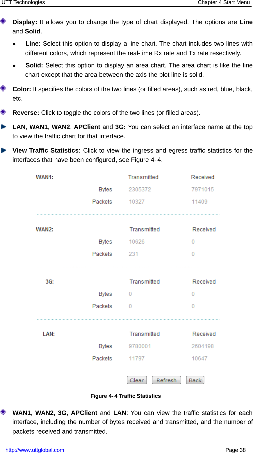
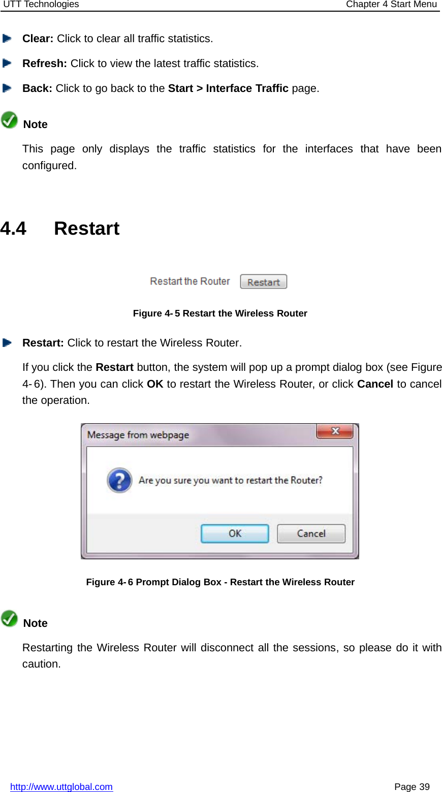
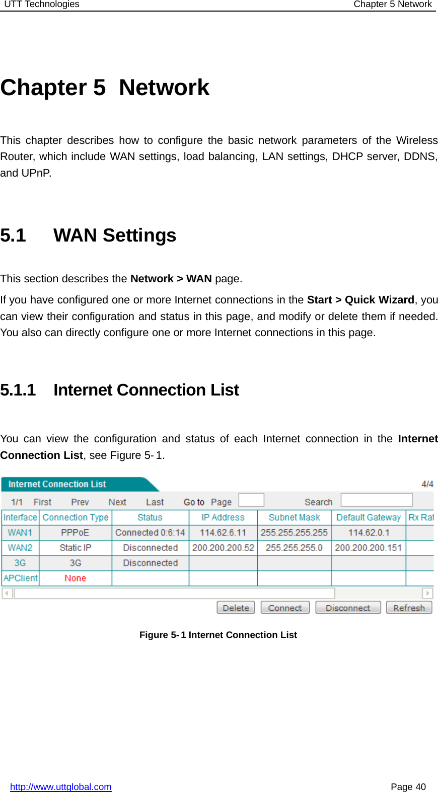
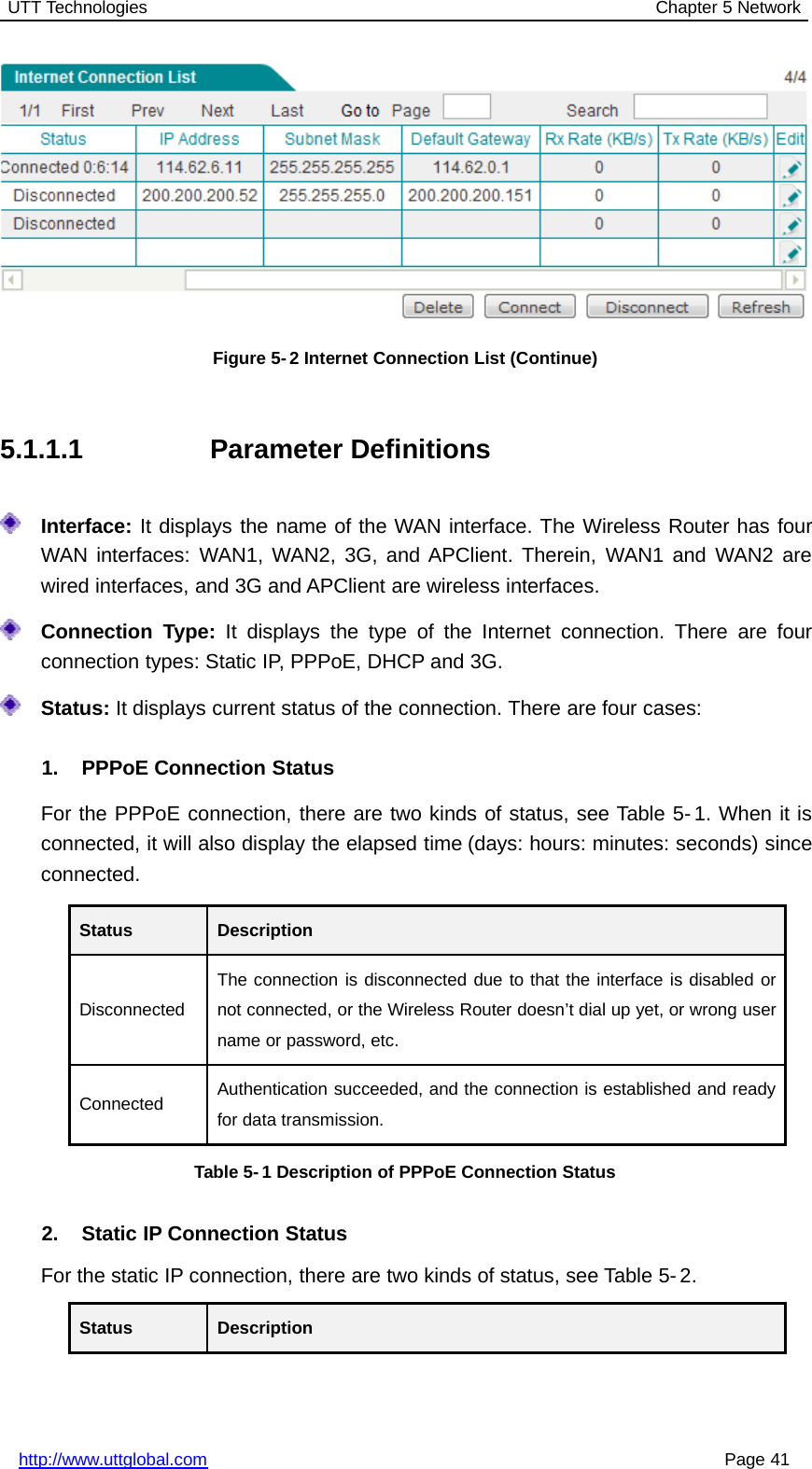
REG02 UTT User Manual
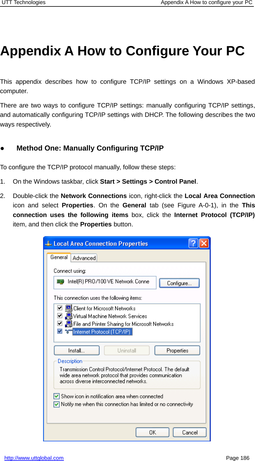
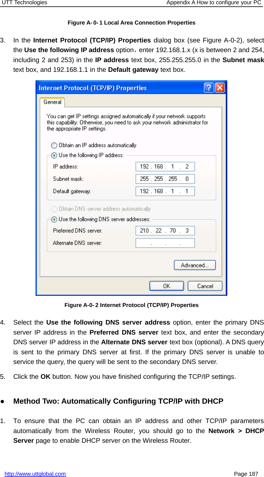
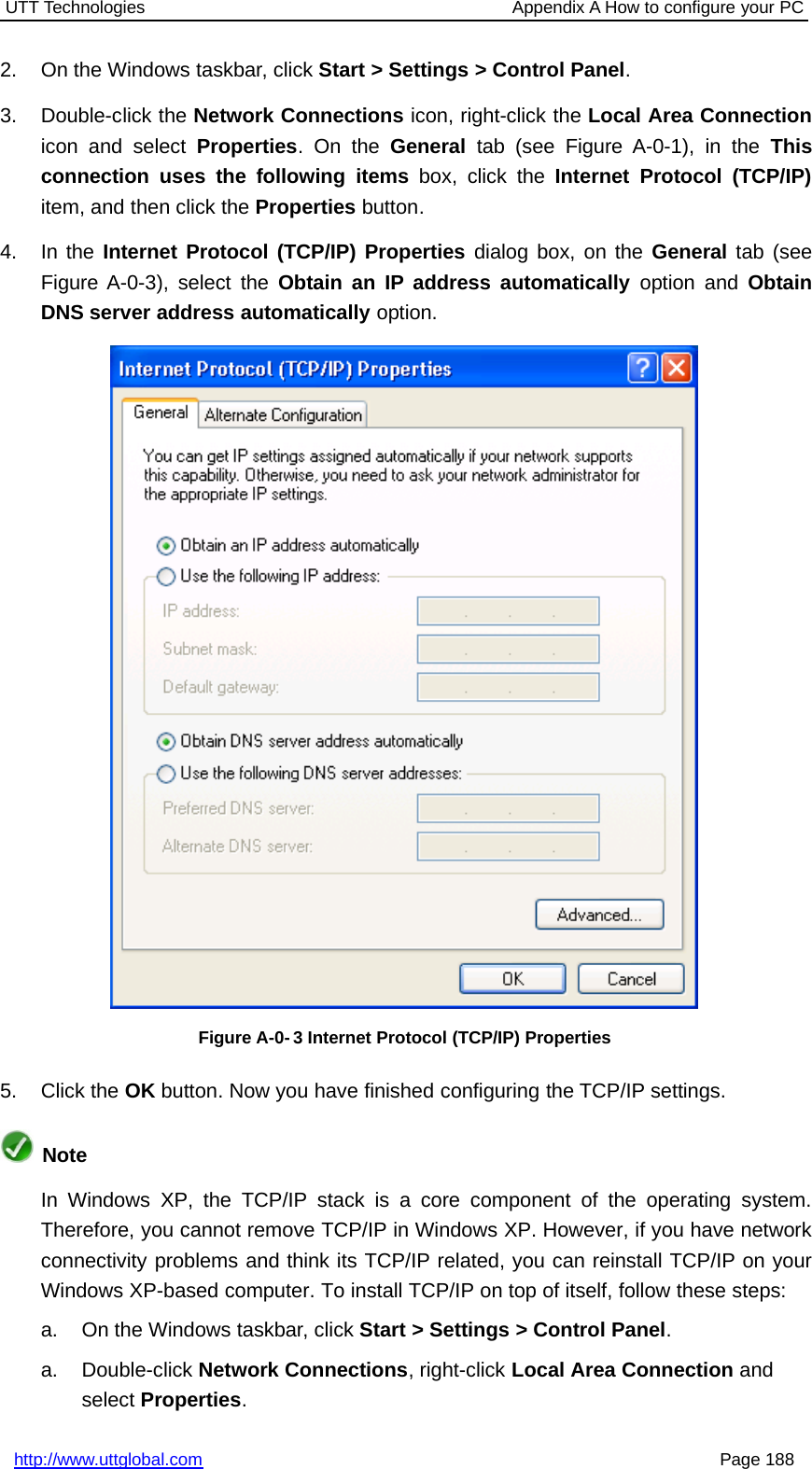
User Manual
Navigation menu
Upload a User Manual
Namespaces
Wiki Guide
HTML
PDF
Info
Views
User Manual
Discussion / Help
Navigation