Ubee Interactive C2104001 BCM 43224 WiFi Card User Manual
Ubee Interactive Corp. BCM 43224 WiFi Card
UserMan_XCNC2104001-revised
1
U S E R ’ S M A N U A L
C2104001
BCM 43224 WiFi Card
Contents
SECTION ONE:
INTRODUCTION............................................................................................3
1. INTRODUCTION............................................................................................................................... 3
1.1
S
COPE
........................................................................................................................................... 3
1.2
F
UNCTION
...................................................................................................................................... 3

2
2 PRODUCT SPECIFICATION ........................................................................................................... 4
2.1
H
ARDWARE
S
PECIFICATION
.......................................................................................................... 4
3. PRODUCT REQUIREMENTS.........................................................................................................4
3.1
H
ARDWARE
R
EQUIREMENTS
......................................................................................................... 4
3.2
H
ARDWARE
A
RCHITECTURE
......................................................................................................... 4
4 FCC NOTICE ......................................................................................................................................6
END PRODUCT LABELING...............................................................................................................6
MANUAL INFORMATION THAT MUST BE INCLUDED ...................................................... …..7
The information contained in this manual has been verified at the time of this manual printing. The
manufacturer reserves the right to make any changes and improvements in the product described in this
manual at any time and without notice.
All registered trademarks are the property of their respective owners.

HON HAI PRECISION IND. CO., LTD.
3
Section One: Introduction
1. Introduction
Project Name: 802.11a/b/g/n (2x2) card based on IC BCM43224 with BGA package.
The typical use model for this embedded device is to allow the client device to be
connected to an 802.11a/b/g/n 2x2 wireless network with infrastructure mode or to
serve as an ad-hoc (peer-to-peer) data path.
1.1 Scope
The Wireless BCM43224 is an available 11n solution in the 2.4/5GHz band, compatible with the IEEE
802.11a/b/g/n. The 802.11 a/g data rate provides for 54, 48, 36, 24, 18, 12, 9, 6Mbps, and 802.11b data rate
provides for 11, 5.5, 2, 1Mbps. In addition, 11n provide MCS8~MCS15 for HT20 which PHY data rate up to
150Mbps; also provide MCS8~MCS15 for HT40 with data rate up to 300Mbps.
1.2 Function
• RoHS and Green Compliant.
• 802.11a/b/g/n 2x2 based on BCM43224.
• PCI-E Half Mini Supported.
• Module is powered by the host with a 3.3V +/- 10% supply (55mVpp ripple).
• Module’s clock source is provided by the on board XTAL Oscillator of 20 MHz (+/-
10ppm).
• JTAG connector will be provided for FA and debug.

HON HAI PRECISION IND. CO., LTD.
4
2 Product Specification
2.1 Hardware Specification
Wireless LAN Standards IEEE 802.11 a/b/g/n
Operating Frequency 2400~2483.5MHz, 5150~5250MHz, 5725~5850MHz
WLAN Data Rate 802.11a/g: 54Mbps with fall back of 48, 36, 24, 18, 12, 9, 6Mbps.
802.11b: 11Mbps with fall back rates of 5.5, 2, and
1Mbps
11n: MCS8~MCS15
Transmitter Output Power Typical 10.0dBm(AV) for 11a
Typical 15.5dBm(AV) for 11b
Typical 15.5dBm(AV) for 11g
Typical 14.5dBm(AV) for HT20
Typical 13.5dBm(AV) for HT40
Receiver Sensitivity Typical –65dBm for MCS15 (HT40) @ 10% PER
Typical –67dBm for MCS14 (HT40) @ 10% PER
Typical –68dBm for MCS13 (HT40) @ 10% PER
Typical –71dBm for MCS12 (HT40) @ 10% PER
Typical –73dBm for MCS11 (HT40) @ 10% PER
Typical –76dBm for MCS10 (HT40) @ 10% PER
Typical –79dBm for MCS9 (HT40) @ 10% PER
Typical –82dBm for MCS8 (HT40) @ 10% PER
Typical –70dBm for MCS15 (HT20) @ 10% PER
Typical –72dBm for MCS14 (HT20) @ 10% PER
Typical –73dBm for MCS13 (HT20) @ 10% PER
Typical –76dBm for MCS12 (HT20) @ 10% PER
Typical –79dBm for MCS11 (HT20) @ 10% PER
Typical –82dBm for MCS10 (HT20) @ 10% PER
Typical –83dBm for MCS9 (HT20) @ 10% PER
Typical –85dBm for MCS8 (HT20) @ 10% PER
Typical –74dBm for 54Mbps @ 10% PER
Typical –76dBm for 48Mbps @ 10% PER
Typical –86dBm for 18Mbps @ 10% PER
Typical –89dBm for 6Mbps @ 10% PER
Typical –89dBm for 11Mbps @ 8% PER
Typical –94dBm for 1Mbps @ 8% PER
3. Product Requirements
3.1 Hardware Requirements
Host Interface PCI-E
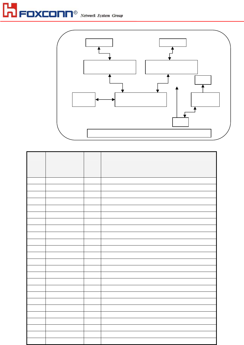
3.2 Hardware Architecture
This specification describes an embedded 802.11a/b/g/n WiFi interface PCA
‘module’ for embedded device products. The module has two antennae. This
module is powered from the host (3.3V) and interfaces to the host with PCIE-half
signals. No switches, indicators or related user interface signals are provided on
this module. An on-board 20 MHz XTAL is included.
HON HAI PRECISION IND. CO., LTD.
5
I/O
PIN DEFINE
PIN S
IGNAL
N
AME
I/O N
OTES
2 3.3V Power supply
3 WPS status LED indicated
4 GND Ground
9 GND Ground
10 WPS status LED indicated
11 REF CLK- Differential PCI-E Clock negative
13 REF CLK+ Differential PCI-E Clock Positive
15 GND Ground
18 GND Ground
21 GND Ground
22 PCIE-Reset Reset to the device from Host
23 PERn0 Differential PCI-E data receive negative
25 PERp0 Differential PCI-E data receive positive
26 GND
27 GND
29 GND
31 PETn0 Differential PCI-E data transmit negative
33 PETp0 Differential PCI-E data transmit positive
34 GND
35 GND
40 GND
44 WLAN Activity LED indicated
50 GND
52 3.3V Power supply
54 GND
ASM3053755T
-
510
3
BCM43224/CPU/P
A
ASM3053755T
-
510
3
Antenn
Antenn
XTAL
20MH
BUCK
MP2120
1.2
3.3
PCI
-
E

HON HAI PRECISION IND. CO., LTD.
6
others
Reserved
4 FCC Notice
Federal Communication Commission Interference Statement
This equipment has been tested and found to comply with the limits for a Class B digital device, pursuant to Part
15 of the FCC Rules. These limits are designed to provide reasonable protection against harmful interference in
a residential installation. This equipment generates, uses and can radiate radio frequency energy and, if not
installed and used in accordance with the instructions, may cause harmful interference to radio communications.
However, there is no guarantee that interference will not occur in a particular installation. If this equipment does
cause harmful interference to radio or television reception, which can be determined by turning the equipment off
and on, the user is encouraged to try to correct the interference by one of the following measures:
- Reorient or relocate the receiving antenna.
- Increase the separation between the equipment and receiver.
- Connect the equipment into an outlet on a circuit different from that
to which the receiver is connected.
- Consult the dealer or an experienced radio/TV technician for help.
This device complies with Part 15 of the FCC Rules. Operation is subject to the following two conditions: (1) This
device may not cause harmful interference, and (2) this device must accept any interference received, including
interference that may cause undesired operation.
FCC Caution: Any changes or modifications not expressly approved by the party responsible for compliance
could void the user's authority to operate this equipment.
IMPORTANT NOTE:
FCC Radiation Exposure Statement:
This equipment complies with FCC radiation exposure limits set forth for an uncontrolled environment. This
equipment should be installed and operated with minimum distance 20cm between the radiator & your body.
This transmitter must not be co-located or operating in conjunction with any other antenna or transmitter.
Operations in the 5.15-5.25GHz band are restricted to indoor usage only
IEEE 802.11b or 802.11g operation of this product in the U.S.A. is firmware-limited to channels 1 through 11.
This device is intended only for OEM integrators under the following conditions:
1) The antenna must be installed such that 20 cm is maintained between the antenna and users, and
2) The transmitter module may not be co-located with any other transmitter or antenna,
3) For all products market in US, OEM has to limit the operation channels in CH1 to CH11 for 2.4G band by
supplied firmware programming tool. OEM shall not supply any tool or info to the end-user regarding to
Regulatory Domain change.
As long as 3 conditions above are met, further transmitter test will not be required. However, the OEM integrator
is still responsible for testing their end-product for any additional compliance requirements required with this
module installed (for example, digital device emissions, PC peripheral requirements, etc.).
IMPORTANT NOTE: In the event that these conditions can not be met (for example certain laptop configurations
or co-location with another transmitter), then the FCC authorization is no longer considered valid and the FCC ID
can not be used on the final product. In these circumstances, the OEM integrator will be responsible for
re-evaluating the end product (including the transmitter) and obtaining a separate FCC authorization.

HON HAI PRECISION IND. CO., LTD.
7
End Product Labeling
This transmitter module is authorized only for use in device where the antenna may be installed such that 20 cm
may be maintained between the antenna and users. The final end product must be labeled in a visible area with
the following: “Contains FCC ID:XCNC2104001”.
Manual Information To the End User
The OEM integrator has to be aware not to provide information to the end user regarding how to install or
remove this RF module in the user’s manual of the end product which integrates this module.
The end user manual shall include all required regulatory information/warning as show in this manual.