Ubee Interactive DVW2110 Cable Modem with RF interface to CATV cable network User Manual 540 00771 005 ok
Ubee Interactive Corp. Cable Modem with RF interface to CATV cable network 540 00771 005 ok
User maual 2
ϬϬʳImportant Safety Warningsʳ
“Installation” should include bonding the screen of
the coaxial cable to the earth at the building
entrance per ANSI/NFPA 70, the National Electrical
Code (NEC), in particular Section 820.93.
Grounding of Outer Conductive Shield of a Coaxial
Cable.
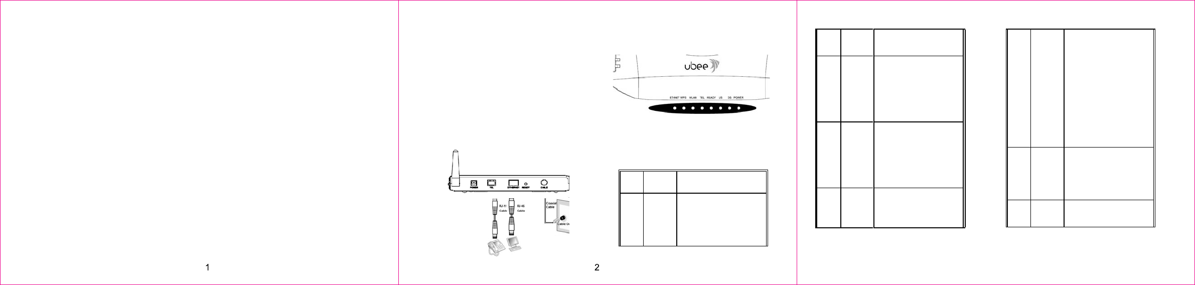
Ϭʳ Installation
Follow the procedures below to install the hardware.
Figure 1 illustrates the connection relationship.
1. Connect one end of the coaxial cable (not
included) to the CABLE port on the modem, and
connect the other end to the cable wall outlet. Be
sure not to bend or over tighten the cables as this
may strain the connector and cause damage. If
you plan to connect the modem and television to
the same wall outlet, you must use a cable line
splitter (not included).
2. Connect one end of the Ethernet cable to an
Ethernet port on the modem, and connect the
other end to the Ethernet port on the PC.
3. Connect one end of the Phone line cable to a
VoIP port (Tel) on the modem, and connect the
other end to the phone port of the phone set.
4. Connect one end of the DC power adapter to the
POWER port on the modem, and connect the
other end to an electric outlet on the wall.
Ϭʳ Connectors on the rear panel of
the Modem
This list of connectors describes where to connect
the cables and power adapter when installing the
cable modem.
1. POWER: This is where you connect the included
RJ11 cable. The other end connects to the phone
line port on the Telephone set.
3. ETHERNET: This is where you connect the
Ethernet RJ45 cable. The other end connects to
the Ethernet port on the PC or NIC.
4. RESET button: Reset the device to factory
defaults by pressing and holding the button for
more than 10 seconds.
5. CABLE Connector: This is where you connect
the coaxial cable (not included) that leads to the
cable splitter (not included) or the cable wall
Figure 1 illustrates the connection relationship
fails.
DSGreen
Indicatesthatdataisbeing
receivedfromthecable
network.Indicatesthatthe
cablemodemhasacquireda
DSchannel.
USGreen
Indicatesthatdataisbeing
transmittedtothecable
network.Indicatesthatthe
cablemodemhasacquiredan
upstreamchannel
ReadyGreen
LEDwillflashslowlywhen
performingupstreamranging.
LEDwillflashquicklywhen
3
power adapter. Remember to use only the power
adapter that came with the Cable Modem.
PleaseseetheLEDdescriptionsbelow:
LEDCOLORDESCRIPTION
PowerGreen
IndicatesthattheDevicehas
successfullycompleted
internalpowerͲontests.LED
flashesifpowerͲonselftest
acquiringanIPAddressand
ConfigurationFile.
LEDwillremainoffifthecable
modemconfigurationfilehas
networkaccesssetto
“disable”.TheLEDwillremain
solidwhenthecablemodem
isregisteredonthecable
network.
Tel Green
LEDMUSTremainsolid,when
onͲhook
LEDMUSTflashwhenaphone
is“OffͲhook”
WPSGreen
LEDflasheswhenpushingthe
HardwareWPS(attheright
outlet.
2. TEL: This is where you connect the phone line
sideofCPE)button.
WLAN Green
WhenWifinetworkis
available,LEDwillbeon.
Ethern
et
Green
Indicatesconnectivity
betweentheEthernetporton
thecablemodemandthePC’s
Ethernetport.LEDflashes
whentrafficisbeingpassed.
ϬϬʳSpecification
Operating Environment: 40 degree C max.
4
Ϭʳ
Safety Notices
1. When this device is placed upright with the aid of
the stand, the stand must be fixed at a 90-degree
angle to the cable modem˗otherwise the device
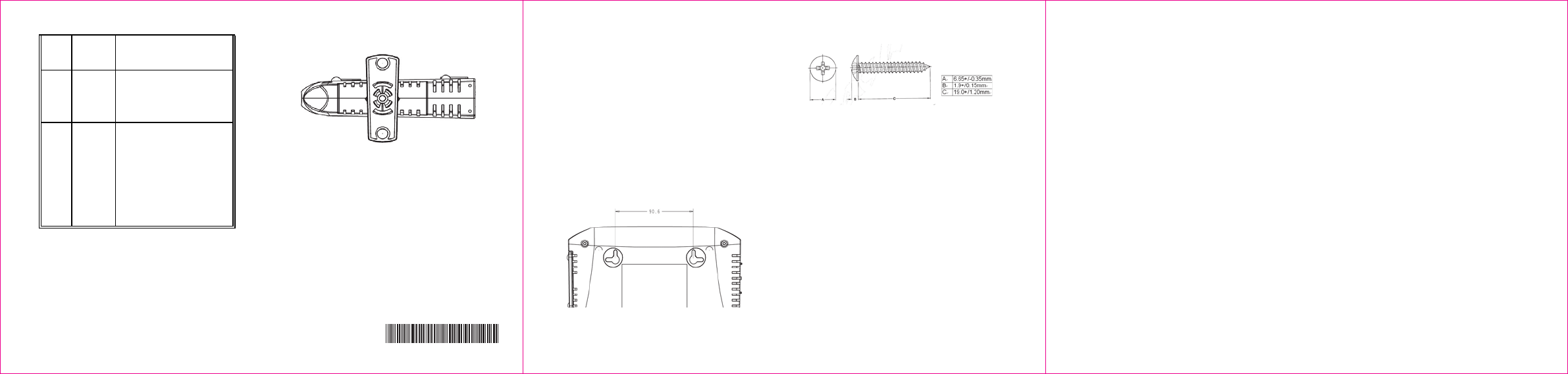
Ϭʳ Wall-Mount Installation
You can mount this device on a wall using the two
mounting brackets on the bottom of the device. We
recommend that you use two round or pan head
screws.
1. Install two screws on a flat surface using Figure 2
on the opposite page as a reference. The screws
should protrude from the wall so that you can fit
the device between the head of the screw and the
wall.
If you install the screws into drywall, use hollow
wall anchors to ensure that the device does not
pull away from the wall due to prolonged strain
5 6
Figure 3: The screw’s size
Figure 2: The distance of the pothook
(Horizontal)
from the cable and power connectors.
540.00771.005
ٟ Federal Communications
Statement
This device has been tested and found to comply
with the limits for a Class B digital device, pursuant
to Part 15 of the FCC Rules. These limits are
designed to provide reasonable protection against
harmful interference in a residential installation. This
device generates, uses, and can radiate radio
frequency energy. If not installed and used in
accordance with the instructions, the device may
cause harmful interference to radio communications.
There is no guarantee, however, that interference
will not occur in a particular installation. If this device
causes harmful interference to radio or television
reception, which can be determined by turning it off
and on, the user can try to correct the interference
by one of the following measures:
- Increase the separation between the device and
the equipment with which it is interfering (for
example, a television or radio).
- Connect the device into an electrical outlet on a
different circuit than the interfered device is
connected.
- Consult the dealer or an experienced radio/TV
technician for help.
ٟ FCC Regulatory Information
This device complies with Part 15 of the FCC Rules.
Operation is subject to the following two conditions:
(1) This device may not cause harmful interference,
and (2) this device must accept any interference
received, including interference that may cause
undesired operation.
FCC Caution: Any changes or modifications not
expressly approved by the party responsible for
compliance could void the user's authority to operate
this device.
IEEE 802.11b or 802.11g operation of this device in
the U.S.A. is firmware-limited to channels 1 through
11.
2. Mount the device onto the wall. Use Figure 3 on
the opposite page as a reference:
Ϭ
Commission (FCC) Interference
ٟ FCC Radiation Exposure Statement
This device complies with FCC radiation exposure
2. "Installation" should include bonding the screen
of the coaxial cable to the earth at the building
entrance per ANSI/NFPA 70, the National
Electrical Code (NEC), in particular Section
820.93; Grounding of Outer Conductive Shield of
a Coaxial Cable.
3. How to disconnect device. The power plug
should be installed near the cable modem to be
easily accessible. If the cable modem becomes
damaged, disconnect the power plug from the AC
wall outlet immediately."
will have the risk of tipping over.
limits set forth for an uncontrolled environment. This
device should be installed and operated at a
minimum distance of 20cm between itself and your
body.
This device must not be co-located or operating in
conjunction with any other antenna or transmitter.