Ubee Interactive DVW222B Cable Modem BCM3379 WeMTA User Manual 540 00750 005
Ubee Interactive Corp. Cable Modem BCM3379 WeMTA 540 00750 005
manual
1
DVW222B D2.0 Voice Wireless Gateway Safety and Installation Product Insert
◆ Federal Communications Commission
(FCC) Interference Statement
This device has been tested and found to comply
with the limits for a Class B digital device, pursuant
to Part 15 of the FCC Rules. These limits are
designed to provide reasonable protection against
harmful interference in a residential installation. This
device generates, uses, and can radiate radio
frequency energy. If not installed and used in
accordance with the instructions, the device may
cause harmful interference to radio communications.
There is no guarantee, however, that interference
will not occur in a particular installation. If this device
causes harmful interference to radio or television
reception, which can be determined by turning it off
and on, the user can try to correct the interference
by one of the following measures:
- Increase the separation between the device and
the equipment with which it is interfering (for
example, a television or radio).
- Connect the device into an electrical outlet on a
different circuit than the interfered device is
connected.
- Consult the dealer or an experienced radio/TV
technician for help.
◆ FCC Regulatory Information
This device complies with Part 15 of the FCC Rules.
Operation is subject to the following two conditions:
(1) This device may not cause harmful interference,
and (2) this device must accept any interference
received, including interference that may cause
undesired operation.
FCC Caution: Any changes or modifications not
expressly approved by the party responsible for
compliance could void the user's authority to operate
this device.
IEEE 802.11b or 802.11g operation of this device in
the U.S.A. is firmware-limited to channels 1 through
11.
◆ FCC Radiation Exposure Statement
This device complies with FCC radiation exposure
limits set forth for an uncontrolled environment. This
device should be installed and operated at a
minimum distance of 20cm between itself and your
body.
This device must not be co-located or operating in
conjunction with any other antenna or transmitter.
2
◆ Safety Notices
1. Installation of the device should include
grounding the coaxial cable to the earth at the
building entrance per ANSI/NFPA 70 and the
National Electrical Code (NEC, in particular,
Section 820.93, Grounding of the Outer
Conductive Shield of a Coaxial Cable).
2. Disconnecting the Device: If the device
becomes damaged or encounters some other
abnormality, disconnect the power plug from the
wall outlet immediately.
3. The device should be installed in a location not
to exceed the maximum temperature of 40
degrees Celsius (104 degrees Fahrenheit).
4. When this device is placed upright with the aid
of the stand, the stand must be fixed at a 90
degree angle to the device. Otherwise, the
device has the risk of tipping over. Refer to
Figure 1.
Figure 1: Device Stand at 90 Degree Angle
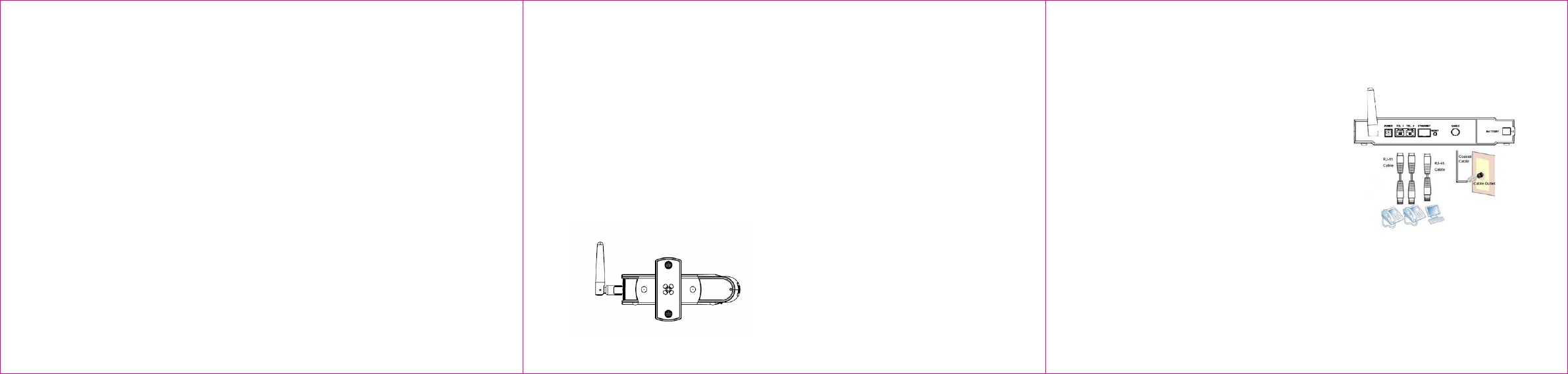
◆ Installation
Follow the procedures below and refer to Figure 2 to
install the device.
1. Connect one end of a coaxial cable (not
included) to the CABLE port on the device.
Connect the other end to a cable splitter or the
cable wall outlet. Be sure not to bend or over-
tighten the cables as this may strain the
connector and cause damage. If you plan to
connect the device and a television to the same
cable wall outlet, you must use a cable line
splitter (not included).
2. Connect one end of the supplied Ethernet cable
to the ETHERNET port on the device. Connect
the other end to the ETHERNET port on a PC.
Note: Category 5e or Category 6 Ethernet
cables with RJ45 connectors must be used
when connecting Ethernet devices to the LAN
ports. This ensures Gigabit Ethernet speeds
(unless the computer does not support it).
3. Connect one end of an RJ11 phone cable to
one of the TEL ports on the device (a port that
has been provisioned for voice service as
specified by the service provider). Connect the
other end to the phone port of the telephone.
Note: If voice service is not provisioned through
the service provider, telephone service is not
available.
4. Connect one end of the power adapter to the
POWER port on the device. Connect the other
end to an electric outlet. Important: Use only
the power adapter that is shipped with the
device.
3
◆ Additional Information on Rear Panel
Connections and Other Information
1. POWER: Use to connect power adapter. Only
use the power adapter that is provided with the
device.
2. TEL1/TEL2: Use to connect the phone line
RJ11 cable. The other end connects to the
phone line port on the Telephone set.
3. ETHERNET: Use to connect the Ethernet RJ45
cable. The other end connects to the Ethernet
port on the PC or NIC.
4. RESET button: Use to reset the device to the
factory defaults. Insert a pointed object into the
button opening and hold for more than 10
seconds. The device resets and reboots.
Note: Not all parameters are reset to factory
defaults. Refer to the User Guide for more
information.
5. CABLE Connector: Use to connect the coaxial
cable (not included) that comes from the cable
splitter (not included) or the cable wall outlet.
6. Battery: Use this slot to contain the battery. The
slot can be opened/closed to insert or replace the
battery.
Note: Only use the battery provided with the
device.
7. WPS (located on the front of the device): Use the
Wi-Fi Protected Setup (WPS) method to connect
PIN-protected Wi-Fi equipment to this device.
Refer to the User Manual for more information.
Figure 2: Rear Panel Connections
4
◆ LEDs on Front Panel of Device
See Figure 3 and the LED descriptions to
understand LED behavior.
Figure 3: Front Panel LEDs
LED COLOR DESCRIPTION
Power Green Indicates the device has
successfully completed internal
power‐on tests. LED flashes if
power‐on self test fails.
DS Green Indicates data is being received
from the cable network. Indicates
the device has acquired a DS
channel.
US Green Indicates data is being
transmitted to the device.
Indicates the device has
acquired an upstream channel
Ready Green LED flashes slowly when
performing upstream ranging.
LED flashes quickly when
acquiring an IP address and
configuration file.
LED remains off if the device
configuration file has network
access set to “disable.” LED
remains solid when the device is
registered on the cable network.
LED COLOR DESCRIPTION
Tel1/Tel2 Green LED MUST remain solid when
on‐hook.
LED MUST flash when a phone
is off‐hook.
WLAN Green LED is on when WiFi network is
available.
LAN Green LED flashes when traffic is being
passed and indicates
connectivity between the
Ethernet port on the device and
the PC’s Ethernet port.
WPS Green LED flashes when pushing the
hardware WPS button.
Battery Green LED is on when the battery is
installed while Adaptor is on and
properly functioning. If there is
no adaptor, the Battery LED is
off, the Power LED blinks, and
the TEL1 LED is on. All other
LEDs are Off. If the battery is at
low power level (30mins left), the
battery LED blinks.
540. 00750. 005
540. 00750. 005
5
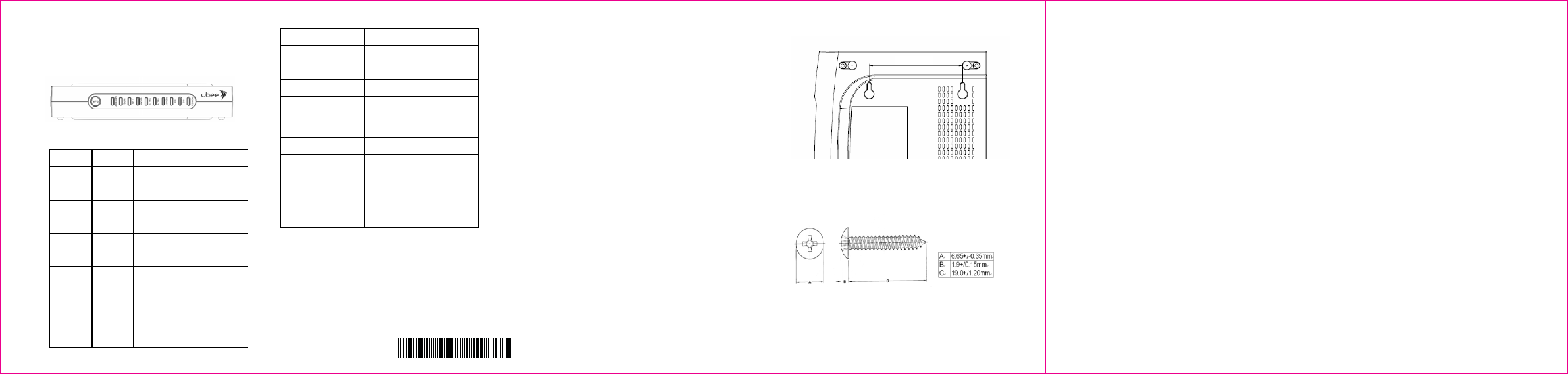
◆ Wall Mount Installation
This device can be mounted on a wall using the two
mounting brackets on the bottom of the device. It is
recommended to use two round or pan head screws
(not included).
1. Install two screws horizontally apart on a wall
using the measurement shown in Figure 4.
The screws should protrude from the wall in
order to fit the device between the head of the
screw and the wall. If the screws are installed
in drywall, use hollow wall anchors to ensure
that the unit does not pull away from the wall
due to prolonged strain from the cable and
power connectors.
2. Remove the device from the product package.
3. Mount the device on the wall.
Refer to Figures 4 and 5 for more details.
Figure 4: Distance (horizontal) Between Brackets
for Screws
Figure 5: Recommended Screw Size
3 ½ inches (88.0 mm)
6