Ubinetics GM401 Dual band module, EGSM900, GSM1900 with MS8GPRS User Manual Reference
Ubinetics Dual band module, EGSM900, GSM1900 with MS8GPRS Reference
Contents
User manual
GM40x GSM/GPRS Module
Reference Manual
UNDOC00048rF
March 2002

ii of vGM40xGSM/GPRS Module Reference: UNDOC00048rF
Copyright © 2001, 2002 UbiNetics (Cayman Islands) Limited. All rights reserved.
UbiNetics Limited, Cambridge Technology Centre, Melbourn, Herts SG8 6DP, United Kingdom.
www.ubinetics.com
No part of this publication may be reproduced, stored in a retrieval system, or transmitted in any form or
by any means, electronic, mechanical, photocopying, recording, or otherwise, without the prior written
permission of UbiNetics Limited.
To the fullest extent permitted by law, UbiNetics Limited assumes no responsibility or liability for errors or
omissions in this publication.
UbiNetics™ is a trademark of UbiNetics (Cayman Islands) Limited. This trademark is registered in
Australia, New Zealand, Singapore, the United Kingdom and the European Community, with registrations
pending in other jurisdictions. The information in this guide is believed to be correct as of the date of
publication. However, our policy is one of continuous development and so the information in this guide is
subject to change without notice, and does not represent a commitment on the part of UbiNetics Limited.
Note on Revision F
This version (Revision F) of the GM40x GSM/GPRS Module Reference Manual documents software version
1.3.1.

GM40x GSM/GPRS Module Reference: UNDOC00048rF iii of v
1.0 Introduction . . . . . . . . . . . . . . . . . . . . . . . . . . . . . . . . . . . . . . . . . . . 1
1.1 Summary Specification . . . . . . . . . . . . . . . . . . . . . . . . . . . . . . . . . . . . . . . . . . . . . . . . . . .2
1.2 Functional Specification. . . . . . . . . . . . . . . . . . . . . . . . . . . . . . . . . . . . . . . . . . . . . . . . . . .2
1.3 Module Interfaces . . . . . . . . . . . . . . . . . . . . . . . . . . . . . . . . . . . . . . . . . . . . . . . . . . . . . . .4
1.4 Software . . . . . . . . . . . . . . . . . . . . . . . . . . . . . . . . . . . . . . . . . . . . . . . . . . . . . . . . . . . . . . .4
2.0 Hardware Specification. . . . . . . . . . . . . . . . . . . . . . . . . . . . . . . . . .6
2.1 Mechanical Characteristics . . . . . . . . . . . . . . . . . . . . . . . . . . . . . . . . . . . . . . . . . . . . . . . .6
2.1.1 Physical & Environmental Characteristics . . . . . . . . . . . . . . . . . . . . . . . . . . . . . . . . . . . . . 6
2.1.2 Mechanical Drawings: GM400/401 . . . . . . . . . . . . . . . . . . . . . . . . . . . . . . . . . . . . . . . . . . 7
2.1.3 Mechanical Drawing: GM404/405 . . . . . . . . . . . . . . . . . . . . . . . . . . . . . . . . . . . . . . . . . . . 9
2.2 Hardware Interface Specification . . . . . . . . . . . . . . . . . . . . . . . . . . . . . . . . . . . . . . . . . . .9
2.2.1 Introduction . . . . . . . . . . . . . . . . . . . . . . . . . . . . . . . . . . . . . . . . . . . . . . . . . . . . . . . . . . . . 9
2.2.2 Pin out diagram and connector orientation . . . . . . . . . . . . . . . . . . . . . . . . . . . . . . . . . . . 10
2.2.3 Interface connector . . . . . . . . . . . . . . . . . . . . . . . . . . . . . . . . . . . . . . . . . . . . . . . . . . . . . 11
2.2.4 Typical application circuit . . . . . . . . . . . . . . . . . . . . . . . . . . . . . . . . . . . . . . . . . . . . . . . . 11
2.2.5 Main power supply . . . . . . . . . . . . . . . . . . . . . . . . . . . . . . . . . . . . . . . . . . . . . . . . . . . . . . 13
2.2.6 Backup power supply . . . . . . . . . . . . . . . . . . . . . . . . . . . . . . . . . . . . . . . . . . . . . . . . . . . 17
2.2.7 SIM Interface . . . . . . . . . . . . . . . . . . . . . . . . . . . . . . . . . . . . . . . . . . . . . . . . . . . . . . . . . . 18
2.2.8 Audio Interface . . . . . . . . . . . . . . . . . . . . . . . . . . . . . . . . . . . . . . . . . . . . . . . . . . . . . . . . . 19
2.2.9 Auxiliary speaker . . . . . . . . . . . . . . . . . . . . . . . . . . . . . . . . . . . . . . . . . . . . . . . . . . . . . . . 21
2.2.10 Digital I/O . . . . . . . . . . . . . . . . . . . . . . . . . . . . . . . . . . . . . . . . . . . . . . . . . . . . . . . . . . . . . 23
2.2.11 Interrupt Output . . . . . . . . . . . . . . . . . . . . . . . . . . . . . . . . . . . . . . . . . . . . . . . . . . . . . . . . 24
2.2.12 Keyboard Interface . . . . . . . . . . . . . . . . . . . . . . . . . . . . . . . . . . . . . . . . . . . . . . . . . . . . . 24
2.2.13 Asynchronous Serial Interface . . . . . . . . . . . . . . . . . . . . . . . . . . . . . . . . . . . . . . . . . . . . . 24
2.2.14 General Purpose I/O . . . . . . . . . . . . . . . . . . . . . . . . . . . . . . . . . . . . . . . . . . . . . . . . . . . . 25
2.2.15 Synchronous Serial Interface . . . . . . . . . . . . . . . . . . . . . . . . . . . . . . . . . . . . . . . . . . . . . . 25
2.2.16 RF Interface Specification . . . . . . . . . . . . . . . . . . . . . . . . . . . . . . . . . . . . . . . . . . . . . . . . 25
2.2.17 Termination of unused lines . . . . . . . . . . . . . . . . . . . . . . . . . . . . . . . . . . . . . . . . . . . . . . . 25
2.3 Electrical Specification. . . . . . . . . . . . . . . . . . . . . . . . . . . . . . . . . . . . . . . . . . . . . . . . . . .26
2.3.1 Standard CMOS logic levels . . . . . . . . . . . . . . . . . . . . . . . . . . . . . . . . . . . . . . . . . . . . . . 26
3.0 Multiplexer . . . . . . . . . . . . . . . . . . . . . . . . . . . . . . . . . . . . . . . . . . .27
3.1 Introduction . . . . . . . . . . . . . . . . . . . . . . . . . . . . . . . . . . . . . . . . . . . . . . . . . . . . . . . . . . .27
3.2 Overview . . . . . . . . . . . . . . . . . . . . . . . . . . . . . . . . . . . . . . . . . . . . . . . . . . . . . . . . . . . . .27
3.2.1 Software Structure . . . . . . . . . . . . . . . . . . . . . . . . . . . . . . . . . . . . . . . . . . . . . . . . . . . . . . 27
3.3 Supported Functions . . . . . . . . . . . . . . . . . . . . . . . . . . . . . . . . . . . . . . . . . . . . . . . . . . . .28
3.4 Implementation . . . . . . . . . . . . . . . . . . . . . . . . . . . . . . . . . . . . . . . . . . . . . . . . . . . . . . . .28
3.4.1 General . . . . . . . . . . . . . . . . . . . . . . . . . . . . . . . . . . . . . . . . . . . . . . . . . . . . . . . . . . . . . . 29
3.4.2 Multiplexer Start-up . . . . . . . . . . . . . . . . . . . . . . . . . . . . . . . . . . . . . . . . . . . . . . . . . . . . . 29
3.4.3 Multiplexer closedown . . . . . . . . . . . . . . . . . . . . . . . . . . . . . . . . . . . . . . . . . . . . . . . . . . . 30
3.4.4 Data channel establishment and release . . . . . . . . . . . . . . . . . . . . . . . . . . . . . . . . . . . . . 30
3.4.5 Data transmission . . . . . . . . . . . . . . . . . . . . . . . . . . . . . . . . . . . . . . . . . . . . . . . . . . . . . . . 30
3.4.6 Control channel commands . . . . . . . . . . . . . . . . . . . . . . . . . . . . . . . . . . . . . . . . . . . . . . . 31
4.0 Host suspend procedure . . . . . . . . . . . . . . . . . . . . . . . . . . . . . . . .33
4.1 Introduction . . . . . . . . . . . . . . . . . . . . . . . . . . . . . . . . . . . . . . . . . . . . . . . . . . . . . . . . . . .33
4.2 Multiplexer . . . . . . . . . . . . . . . . . . . . . . . . . . . . . . . . . . . . . . . . . . . . . . . . . . . . . . . . . . . .33

iv of vGM40xGSM/GPRS Module Reference: UNDOC00048rF
4.3 Module power modes . . . . . . . . . . . . . . . . . . . . . . . . . . . . . . . . . . . . . . . . . . . . . . . . . . .33
4.4 Host wake-up events . . . . . . . . . . . . . . . . . . . . . . . . . . . . . . . . . . . . . . . . . . . . . . . . . . . . 34
4.5 Host suspend operation . . . . . . . . . . . . . . . . . . . . . . . . . . . . . . . . . . . . . . . . . . . . . . . . . 34
4.5.1 Host suspend procedure . . . . . . . . . . . . . . . . . . . . . . . . . . . . . . . . . . . . . . . . . . . . . . . . . 34
4.5.2 Module wake-up behaviour . . . . . . . . . . . . . . . . . . . . . . . . . . . . . . . . . . . . . . . . . . . . . . . 34
4.5.3 Host wake-up behaviour . . . . . . . . . . . . . . . . . . . . . . . . . . . . . . . . . . . . . . . . . . . . . . . . . 35
4.5.4 Timing diagram . . . . . . . . . . . . . . . . . . . . . . . . . . . . . . . . . . . . . . . . . . . . . . . . . . . . . . . . 35
5.0 Integration Guidelines . . . . . . . . . . . . . . . . . . . . . . . . . . . . . . . . . .37
5.1 RF . . . . . . . . . . . . . . . . . . . . . . . . . . . . . . . . . . . . . . . . . . . . . . . . . . . . . . . . . . . . . . . . . . 37
5.1.1 Receiver . . . . . . . . . . . . . . . . . . . . . . . . . . . . . . . . . . . . . . . . . . . . . . . . . . . . . . . . . . . . . . 37
5.1.2 Transmitter . . . . . . . . . . . . . . . . . . . . . . . . . . . . . . . . . . . . . . . . . . . . . . . . . . . . . . . . . . . . 38
5.1.3 Sourcing antennae . . . . . . . . . . . . . . . . . . . . . . . . . . . . . . . . . . . . . . . . . . . . . . . . . . . . . . 38
5.2 EMC. . . . . . . . . . . . . . . . . . . . . . . . . . . . . . . . . . . . . . . . . . . . . . . . . . . . . . . . . . . . . . . . . 39
5.2.1 Radiation by the application . . . . . . . . . . . . . . . . . . . . . . . . . . . . . . . . . . . . . . . . . . . . . . . 39
5.2.2 RF interference . . . . . . . . . . . . . . . . . . . . . . . . . . . . . . . . . . . . . . . . . . . . . . . . . . . . . . . . . 39
5.3 Ground plane connection . . . . . . . . . . . . . . . . . . . . . . . . . . . . . . . . . . . . . . . . . . . . . . . .40
5.4 Power supply . . . . . . . . . . . . . . . . . . . . . . . . . . . . . . . . . . . . . . . . . . . . . . . . . . . . . . . . . . 40
5.5 Mechanical . . . . . . . . . . . . . . . . . . . . . . . . . . . . . . . . . . . . . . . . . . . . . . . . . . . . . . . . . . .40
5.6 Firmware upgrading . . . . . . . . . . . . . . . . . . . . . . . . . . . . . . . . . . . . . . . . . . . . . . . . . . . . 40
6.0 Regulatory Approval . . . . . . . . . . . . . . . . . . . . . . . . . . . . . . . . . . .41
7.0 Definitions and Abbreviations . . . . . . . . . . . . . . . . . . . . . . . . . . . .45
7.0.1 Definitions . . . . . . . . . . . . . . . . . . . . . . . . . . . . . . . . . . . . . . . . . . . . . . . . . . . . . . . . . . . . . 45
7.0.2 Syntactical Definitions . . . . . . . . . . . . . . . . . . . . . . . . . . . . . . . . . . . . . . . . . . . . . . . . . . . 45
7.0.3 Abbreviations . . . . . . . . . . . . . . . . . . . . . . . . . . . . . . . . . . . . . . . . . . . . . . . . . . . . . . . . . . 45
8.0 AT Commands: Introduction . . . . . . . . . . . . . . . . . . . . . . . . . . . . .47
8.1 Overview . . . . . . . . . . . . . . . . . . . . . . . . . . . . . . . . . . . . . . . . . . . . . . . . . . . . . . . . . . . . .47
8.2 Format of the AT Command String and Result Code . . . . . . . . . . . . . . . . . . . . . . . . . . . 47
8.2.1 Types of Commands . . . . . . . . . . . . . . . . . . . . . . . . . . . . . . . . . . . . . . . . . . . . . . . . . . . . 47
8.2.2 Command Line Editing . . . . . . . . . . . . . . . . . . . . . . . . . . . . . . . . . . . . . . . . . . . . . . . . . . . 48
8.2.3 Command Line Termination . . . . . . . . . . . . . . . . . . . . . . . . . . . . . . . . . . . . . . . . . . . . . . . 48
8.2.4 Command Formatting . . . . . . . . . . . . . . . . . . . . . . . . . . . . . . . . . . . . . . . . . . . . . . . . . . . 48
8.2.5 Command Line Echo . . . . . . . . . . . . . . . . . . . . . . . . . . . . . . . . . . . . . . . . . . . . . . . . . . . . 48
8.2.6 Concatenation . . . . . . . . . . . . . . . . . . . . . . . . . . . . . . . . . . . . . . . . . . . . . . . . . . . . . . . . . 48
8.2.7 Response Code Format . . . . . . . . . . . . . . . . . . . . . . . . . . . . . . . . . . . . . . . . . . . . . . . . . . 48
8.2.8 Response Code Suppression . . . . . . . . . . . . . . . . . . . . . . . . . . . . . . . . . . . . . . . . . . . . . 48
8.2.9 Final Result Code . . . . . . . . . . . . . . . . . . . . . . . . . . . . . . . . . . . . . . . . . . . . . . . . . . . . . . . 48
8.2.10 Intermediate Result Code . . . . . . . . . . . . . . . . . . . . . . . . . . . . . . . . . . . . . . . . . . . . . . . . 49
8.2.11 Unsolicited Result Code . . . . . . . . . . . . . . . . . . . . . . . . . . . . . . . . . . . . . . . . . . . . . . . . . . 49
9.0 Commands Specified by GSM 07.07 . . . . . . . . . . . . . . . . . . . . . . .50
9.1 General Commands . . . . . . . . . . . . . . . . . . . . . . . . . . . . . . . . . . . . . . . . . . . . . . . . . . . . 50
9.2 Call Control Commands . . . . . . . . . . . . . . . . . . . . . . . . . . . . . . . . . . . . . . . . . . . . . . . . . 52
9.3 Network Service Related Commands . . . . . . . . . . . . . . . . . . . . . . . . . . . . . . . . . . . . . . . 59
9.4 Mobile Equipment Control and Status Commands . . . . . . . . . . . . . . . . . . . . . . . . . . . . . 73
9.5 Mobile Equipment Errors. . . . . . . . . . . . . . . . . . . . . . . . . . . . . . . . . . . . . . . . . . . . . . . . . 80
9.6 Commands from TIA IS-101 . . . . . . . . . . . . . . . . . . . . . . . . . . . . . . . . . . . . . . . . . . . . . .82
10.0 Commands Specified by GSM 07.05 . . . . . . . . . . . . . . . . . . . . . . .84

GM40x GSM/GPRS Module Reference: UNDOC00048rF v of v
10.1SMS Parameter Definitions. . . . . . . . . . . . . . . . . . . . . . . . . . . . . . . . . . . . . . . . . . . . . . . .84
10.1.1 Message Storage Parameters . . . . . . . . . . . . . . . . . . . . . . . . . . . . . . . . . . . . . . . . . . . . . 84
10.1.2 Message Data Parameters . . . . . . . . . . . . . . . . . . . . . . . . . . . . . . . . . . . . . . . . . . . . . . . 85
10.2General Configuration Commands . . . . . . . . . . . . . . . . . . . . . . . . . . . . . . . . . . . . . . . . .87
10.3Message Configuration Commands . . . . . . . . . . . . . . . . . . . . . . . . . . . . . . . . . . . . . . . .88
10.4Message Receiving and Reading Commands . . . . . . . . . . . . . . . . . . . . . . . . . . . . . . . .90
10.5Message Sending and Writing Commands . . . . . . . . . . . . . . . . . . . . . . . . . . . . . . . . . . .94
11.0 Commands specified within V.25ter Referenced by GSM 07.07 .97
11.1Generic DCE Control Commands . . . . . . . . . . . . . . . . . . . . . . . . . . . . . . . . . . . . . . . . . .97
11.2Call Control Commands and Responses. . . . . . . . . . . . . . . . . . . . . . . . . . . . . . . . . . . .104
12.0 Commands Specified by ITU-T Rec. T.32 . . . . . . . . . . . . . . . . . .109
12.1Action commands . . . . . . . . . . . . . . . . . . . . . . . . . . . . . . . . . . . . . . . . . . . . . . . . . . . . .109
12.2DCE responses . . . . . . . . . . . . . . . . . . . . . . . . . . . . . . . . . . . . . . . . . . . . . . . . . . . . . . .110
12.3Services commands . . . . . . . . . . . . . . . . . . . . . . . . . . . . . . . . . . . . . . . . . . . . . . . . . . .121
13.0 Condat-specific commands. . . . . . . . . . . . . . . . . . . . . . . . . . . . .139
13.1CME and CMS Result Codes. . . . . . . . . . . . . . . . . . . . . . . . . . . . . . . . . . . . . . . . . . . . .145
14.0 Additional AT Commands for GPRS. . . . . . . . . . . . . . . . . . . . . . . 149
14.1Introduction . . . . . . . . . . . . . . . . . . . . . . . . . . . . . . . . . . . . . . . . . . . . . . . . . . . . . . . . . .149
14.2Commands specified by GSM Rec. 07.07. . . . . . . . . . . . . . . . . . . . . . . . . . . . . . . . . . .149
14.3UbiNetics General Purpose Commands . . . . . . . . . . . . . . . . . . . . . . . . . . . . . . . . . . . .159
15.0 References. . . . . . . . . . . . . . . . . . . . . . . . . . . . . . . . . . . . . . . . . .171
16.0 Alphabetical List of AT Commands. . . . . . . . . . . . . . . . . . . . . . .172

Introduction
1of 176 GM40x GSM/GPRS Module Reference: UNDOC00048rF
1.0 Introduction
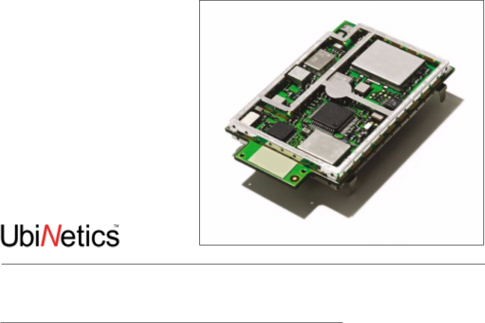
This document specifies the functionality of the UbiNetics GM40x dual-band GSM/GPRS modules:
●GM400 is a 900 E-GSM and 1800 GSM dual-band module
●GM401 is a 900 E-GSM and 1900 GSM dual-band module
●GM404 is a low- profile 900 E-GSM and 1800 GSM dual-band module
●GM405 is a low-profile 900 E-GSM and 1900 GSM dual-band module.
Both modules provide multislot GPRS operation to MS8 specification.
The products provide GSM/GPRS mobile communication capability, suitable for embedding in PDAs and
other devices.

Introduction
GM40x GSM/GPRS Module Reference: UNDOC00048rF 2 of 176
1.1 Summary Specification
1.2 Functional Specification
Parameter Qualifier Specification Notes
Class Dual band
GM400 E-GSM 900 Power Class 4 (2W)
GSM1800 Power Class 1 (1W)
Dual band
GM401 E-GSM 900 Power Class 4 (2W)
GSM1900 Power Class 1 (1W)
Dual band
GM404 E-GSM 900 Power Class 4 (2W)
GSM1800 Power Class 1 (1W)
Dual band
GM405 E-GSM 900 Power Class 4 (2W)
GSM1900 Power Class 1 (1W)
GPRS class Multislot Class The product provides multislot operation to
MS 8 Maximum total number of
slots is 5
Maximum number of
receive slots is 4
Maximum number of
transmit slots is 1
Mobile station class The product provides a Mobile Station of
class B (Non-concurrent dual-mode GSM/
GPRS)
RF RF bands E-GSM 900:
Tx: 880 – 915 Rx: 925 – 960 MHz
GSM 1800:
Tx: 1710 – 1785, Rx: 1805 – 1880 MHz
GSM 1900:
Tx: 1850 – 1910, Rx: 1930 – 1990 MHz
Receiver sensitivity Better than -104 dBm at 900 GSM
Better than -102 dBm at 1800/1900 GSM
Selectivity Better than 9dB at 200KHz
Better than 41dB at 400KHz
Dynamic range ~89dB typical for 900 GSM
~87dB typical for 1800 GSM
Electrical
performance Conforms to ETSI 11.10
RF connection Signal and ground PCB pads for
attachment of appropriate RF

Introduction
3of 176 GM40x GSM/GPRS Module Reference: UNDOC00048rF
Approvals Safety
Radio
Protocol
EMC
SAR
Network
Environmental
EN60950
3GPP 51.010
3GPP 51.010
EN 301 489
ES59005
GCF PTCRB
ETS 300 019
Europe
Safety
Radio
Protocol
EMC
SAR
Network
Environmental
UL60950 edition 3
FCC part 24
FCC part 15
ANSI C95.1
PTCRB
Customer specific
USA
Audio Voice 2 Microphone and 2 ear-piece interfaces
Alert Sounder output
Echo
Cancellation Sufficient for small handset enclosures and
desktop use 32m second maximum
delay; attenuation
approximately 40 dB
GSM Data Asynchronous
transparent and non-
transparent
9.6kbps / 14.4kbps
GPRS Data Asynchronous 9.05, 13.4, 15.6 and 21.4kbps per slot
GSM Fax Transparent 9.6kbps and 14.4kbps
SMS Full ETSI SMS compliant, including cell
broadcast
Memory RAM 6Mbit
Flash 16Mbit
SIM The module supports the following SIM
card types:
Plug-in SIM card 3V
Plug-in SIM card 3V/5V
Only SIM cards conforming to ETS 300
607-1 are supported, tested against UK
and other European Network Provider SIM
cards
Temperature
monitoring On-board over-temperature protection
(+80ºC)1
Power supply Voltage 3.6V nominal
3.3V minimum 3.2V minimum during
(2A) TX burst
Power
consumption
(average)
Shutdown current 70µAnominal
Stand-by current 3.2mA nominal
Talk current See table on page 13
1.Calls are ended if the internal temperature reaches +80ºC. In worst case conditions, the internal temperature of the
module can be up to 20ºC higher than ambient, so temperature protection may trigger at 60ºC ambient temperature.

Introduction
GM40x GSM/GPRS Module Reference: UNDOC00048rF 4 of 176
1.3 Module Interfaces
1.4 Software
Parameter Qualifier Specification Notes
Display interface SPI (5 wire) 2.9 V logic levels
Keyboard 5 x 5 matrix 5 x inputs (rows)
5 x outputs (columns) 2.9 V logic levels
Serial interface 4 lines (TXD, RXD,
RTS, CTS) Compatible with UART 16C750
device 2.9 V logic levels.
General Purpose I/O 3 x GPIO
Parameter Qualifier Specification
Protocol stack Layer 1 / 2 / 3 GSM/GPRS Dual Band Protocol Stack
Layer 2 / 3 Supplementary
Services Caller line identification
Call forwarding
Call waiting / call hold
Layer 1 Codec Support Firmware providing support for:
FR, HR, EFR (Dual band)
Subsidy protection Network personalisation according to GSM 02.22
for:
Network Operator Lock
Service Provider Lock
Lock to First SIM
Device drivers Drivers for all hardware
devices in the core design RF
SIM
UART
Audio control
Power Supply control
External interfaces Serial interface with data rate
of 56Kbps (57600bps) Serial interface supporting AT commands, with
software multiplexer for use in GPRS Class B mode,
or for multiple AT command streams.
Multiplexer supports a subset of ETSI 07.10
specification
AT command interpreter supports a subset of ETSI
07.05 and 07.07 specifications, including V.25
Application software Diallers
AT Exerciser
Flash Upgrader
Multiplexer
For PC and other operating systems
For driving the module using AT commands
For upgrading module firmware

Introduction
5of 176 GM40x GSM/GPRS Module Reference: UNDOC00048rF
4
.
4
SIM Tool kit (release 98
compliant, ETSI standard
11.14, Version 7.3.1)
Functions supported Call Control
Cell Broadcast Download
Event Download
MO Short Message Control
More Time
Polling Off
Poll Interval
Provide Local Information
Refresh
Send DTMF
Send Short Message
Send SS
Send USSD
Set Up Call
Set Up Event List
SMS-PP Download
Timer Management
Timer Expiration
Run AT Command
MMI MMI functions supported Support available for small or full MMI: details of API
available upon request
Drivers Keypad
SPI
GPI/O

Hardware Specification
GM40x GSM/GPRS Module Reference: UNDOC00048rF 6 of 176
2.0 Hardware Specification
2.1 Mechanical Characteristics
2.1.1 Physical & Environmental Characteristics
Parameter Qualifier Specification
Form PCB, components on both sides, with screening can on both sides
Size & weight Dual band
Weight
Overall size:
50.6 X 31 X 5.25 mm nominal
15 grams
Temperature
& Humidity Storage -20ºC to +70ºC at 93% relative humidity
-40ºC to +70ºC at 30% relative humidity
Operational -20ºC to +55ºC at a relative humidity of 93%
Vibration (no damage) Random vibration test compliant with IEC60068-2-64 standard
Marking Type and model number
Serial number and IMEI number (alphanumeric and bar code)
Ubinetics logo
Hardware
interface Characteristics As described in the “Hardware Interface Specification” on page 9.
Shock Shock test 450cm/s impact (impact time 2 - 2.8ms)
Drop test 1 metre drop test
Hardware Specification
7of 176 GM40x GSM/GPRS Module Reference: UNDOC00048rF
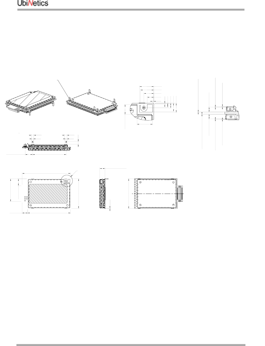
2.1.2 Mechanical Drawings: GM400/401
TITLE
DRAWING No.
TTED OR REPRODUCED
AUTHORISED
DIMS
SCALE
DATE
DRAWN CHECKED
FINISH
VERSION DATE CHANGE
SHT
OF
SIG
Group
Company
UBINETICS LTD
a
5.55 MAX
MODULE HEIGHT
0.50
2.75
4.15
5.55
5.95
0.50
1.70
2.00
3.40
3.80
7.80
±0.30
MOUNTING PIN CENTRES
35.20
±0.15
2.50
1.60
2.50
1.60
3.00
MAX
(LID THICKNESS)
0.20
MAX
(LID ASSEMBLY TOL.)
0.10
2.10 MAX
(FENCE)
MAX
(SOLDER ALLOWANCE)
0.05
MAX
(SOLDER ALLOWANCE)
0.05
2.10 MAX
(FENCE)
MAX
(LID ASSEMBLY TOL.)
0.10
MAX
(LID THICKNESS)
0.20
50.60
±0.25
44.90
±0.25
31.00
±0.25
MOUNTING PINS
31.25
±0.15
7.20
±0.25
23.80
±0.25
0.30
6.50
±0.10
4.15
±0.10
REF5.70
2
-D r 1
N/A25-Sep-01mm
1
N/A
SJW2:1
SJW08-Oct-011
r1
r1
NOTES:
1. THIS DRAWING SUPERCSEDES AND REPLACES
DRAWING UNASM00126.
2. MODULE REQUIRES A THERMAL RESISTANCE
WHEN MOUNTED TO THE HOST PCB. SPECIFIC
REQUIREMENTS SHOWN BELOW:
-MS8 26 °C/W
-MS10 19 °C/W
-MS12 12 °C/W
2. MODULE PCB DIMENSIONS ±0.25MM.
PLACEMENT TOLERANCES ±0.1MM
3. MOUNTING HOLE DETAILS SHOWN ON SHEET 2
SEE DETAIL A
SEE DETAIL B
DETAIL A
SCALE 5:1
ANTENNA PAD DETAIL
DETAIL B
SCALE 5:1
THIS PIN MUST BE
CONNECTED TO GROUND
ON HOST PCB
Hardware Specification
GM40x GSM/GPRS Module Reference: UNDOC00048rF 8 of 176
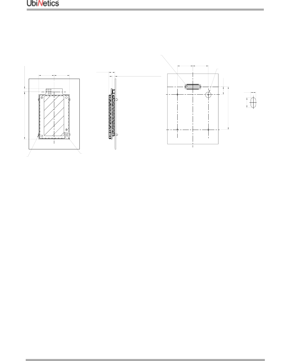
REF BOARD TO BOARD HEIGHT
(DEFINED BY CONNECTOR SYSTEM)
3.00
15.50
±0.35
15.50
±0.35
3.10
±0.35
47.50
±0.35
6.3 MAX
15.4815.48
7.80
43.00
2.00
1.00
NOTES:
1. MOUNTING HOLE DIMENSIONS INCLUDE AN ALLOWANCE FOR
TOLERANCES ON PLACEMENT OF CONNECTOR,MOUNTING
PINS AND MODULE.
2. CUSTOMER TO MAKE ALLOWANCE FOR DRILL HOLE
PLACEMENT TOLERANCE ON THEIR MOTHERBOARD.
3. TOLERANCE ON PLACEMENT OF MATING CONNECTOR ASSUMED
TO BE ±0.1mm. CUSTOMER TO MAKE ALLOWANCE IF TOLERANCE
IS DIFFERENT.
MOUNTING DETAIL
EXAMPLE
SEE DETAIL C
UNCON00200
MATING CONNECTOR
DETAIL C
SCALE 1
1
0:1
ANTENNA PAD
THIS PIN
TO BE
CONNECTED
TO GROUND
Hardware Specification
9of 176 GM40x GSM/GPRS Module Reference: UNDOC00048rF
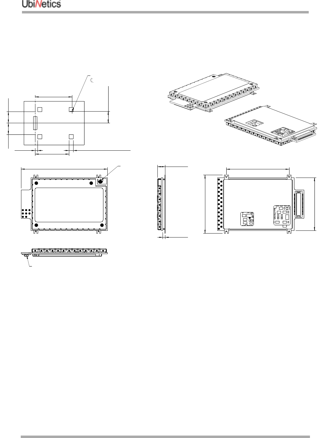
2.1.3 Mechanical Drawing: GM404/405
2.2 Hardware Interface Specification
2.2.1 Introduction
This section describes the hardware interface specification for the dual-band GSM/GPRS Module. A 50-
way board-to-board connector is used to interface with the host hardware platform. The specification of
this connector is given on “Pin out diagram and connector orientation” on page 10. An antenna pad is
provided for the RF interface.
Note:
●The module must be power grounded by the mounting point shown in “Pin out diagram and connector
orientation” on page 10.
●The circuit diagrams in this section show circuits internal to the module. Exceptions to this are the dia-
grams in “Backup power supply” on page 17, “Auxiliary microphone” on page 20, “Auxiliary speaker”
on page 21 (3-wire headset) and “Sounder output” on page 22, where components may be required in
the host.
(50.9 MAX)50.6
(31.3 MAX)31.0
5.1 MAX
1.5 REF
3.0
39.8
SQR. TYP 4 PLACES5.0
13.413.4
REF34.2
REF36.8
REF43.4
REF13.7
ANTENNA
CONNECTION
PAD
SCALE 2:1
SCALE 2:1
RELATIVE POSITION OF
OF ANTENNA
SUGGESTED MOUNTING
DETAIL
SCALE 1:1
1.5 MM BOARD TO BOARD
CONNECTOR
Hardware Specification
GM40x GSM/GPRS Module Reference: UNDOC00048rF 10 of 176
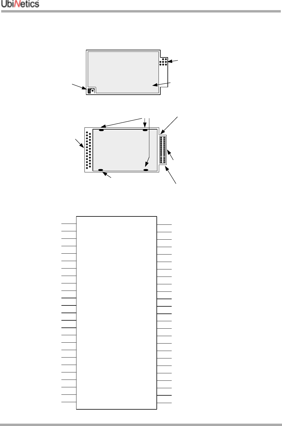
2.2.2 Pin out diagram and connector orientation
RF
Connection
Pads
PIN 50
PIN 1
Mechanical mounting
and electrical
grounding point
Mechanical
mounting point
TOP VIEW
(RF) RF Screening
can
BOTTOM
VIEW
(BASEBAND)
ATE test
points
50 way board to
board conector
(see DETAIL 1)
ATE test
points
PWR
PWR
PWR
GND
MIC1P
MIC1N
AUXI
GND
SPI_DATA
SPI_CLK
SPI_CS
SPI_D/C
SPI_RST
GPIO1
GPIO2
ON/OFF
RESET
HOST_WAKEUP
SOUNDER
RTS
RXD
HOST_STATUS
INT_OUT
CTS
VDDS
PWR
PWR
PWR
PWR_RTC
SPK1P
SPK1N
SPK2P
SPK2N
AUXV0
SIM_VDD
SIM_I/O
SIM_CLK
SIM_RST
KBC0
KBC1
KBC2
KBC3
KBC4
KBR0
KBR1
KBR2
KBR3
KBR4
TXD
1
3
5
7
9
11
13
15
17
19
21
23
25
27
29
31
33
35
37
39
41
43
45
47
49
2
4
6
8
10
12
14
16
18
20
22
24
26
28
30
32
34
36
38
40
42
44
46
48
50
GPIO3
DETAIL 1

Hardware Specification
11 of 176 GM40x GSM/GPRS Module Reference: UNDOC00048rF
2.2.3 Interface connector
The board-to-board connectors required in the host, to provide the interface with the modules are as
follows:
GM400/401
This plug is available to special order only, and you should allow a lead time of 12 to 14 weeks for delivery
from the manufacturer.
GM404/405
This is a comparatively new part, and may not yet be in all Hirose catalogues.
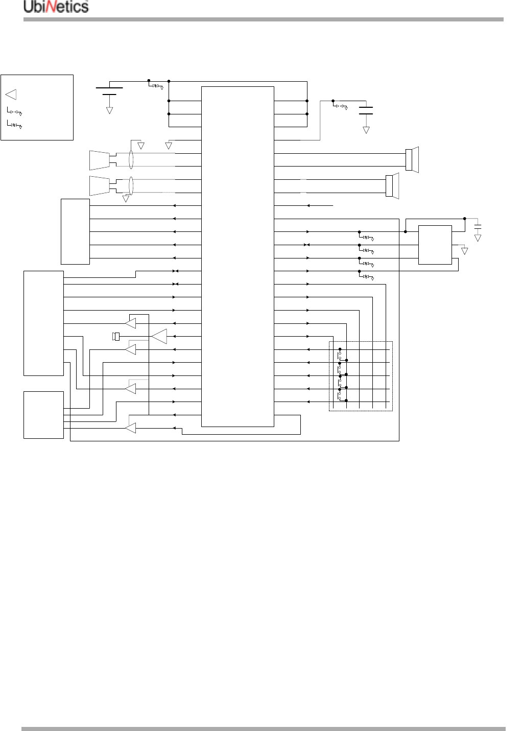
2.2.4 Typical application circuit
This is a circuit for a typical application incorporating the GSM/GPRS module, using the following
interfaces:
●LCD
●Serial port
●Keyboard
●SIM
●GPI/O
●2 speakers
●2 microphones
●Main battery
●Backup battery
Type Pins Pitch Type Manufacturer Part number
Plug1
1.Although catalogued as a plug, this is a ‘female’ receptacle
50-way 0.5mm Vertical ‘M’ type SMK (http://www.smk.co.jp) CPB7250-6211
Type Pins Pitch Type Manufacturer Part number
Socket 50-way 0.5mm Vertical SMT Hirose DF23C-50DS-0.5V(51)
Hardware Specification
GM40x GSM/GPRS Module Reference: UNDOC00048rF 12 of 176
2
4
6
8
10
12
14
16
24
22
20
18
34
32
30
28
26
36
38
40
42
44
46
48
50
1
3
5
7
9
11
13
15
23
21
19
17
33
31
29
27
25
35
37
39
41
43
45
47
49
PWR
PWR
PWR
PWR
PWR
PWR
GND PWR_RTC
MIC1P
MIC1N
MIC2P
SPI_DATA
SPI_CLK
SPI_CS
SPI_D/C
SPI_RST
GPIO1
GPIO2
ON/~OFF
~RESET
HOST-WAKEUP
SOUNDER
RTS
RXD
HOST_STATUS
INT_OUT
CTS
VDDS
SPK1P
SPK2P
SPK1N
SPK2N
AUXVO
SIM_VDD
SIM_I/O
SIM_CLK
SIM_RST
KBC0/GPO0
KBC1/GPO1
KBC2/GPO2
KBC3/GPO3
KBC4/GPO4
KBR0/GPI0
KBR4/GPI4
KBR3/GPI3
KBR2/GPI2
KBR1/GPI1TXD
V_BAT (monitor)
SPEAKER (MAIN)
MIC (MAIN)
MAIN
BATTERY SUPERCAP
V_BAT
SPEAKER (AUX)
VCC
I/O
CLK RST
VPP
GND
SIM
100n
Use low capacitance
tranzorbs on SIM
connections
TZ
TZ
TZ
TZ
LCD
SG
MIC (AUX)
TYPICAL MODULE APPLICATION
GND
GPIO3
LS
LS
LS
LS
TZ
SG
TZ
SPARK GAP
TRANZORB
LEVEL SHIFTER
LS
LEGEND
HOST
INTERFACE
SERIAL
PORT
INTERFACE
BUF
Hardware Specification
13 of 176 GM40x GSM/GPRS Module Reference: UNDOC00048rF
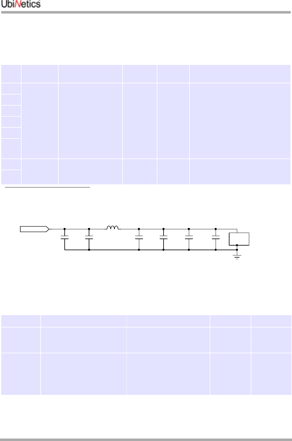
2.2.5 Main power supply
Note that Default State is the pin state on power up.
Pin out
Power input circuit
Average Power Consumption
All power consumption specifications are given at the nominal voltage of 3.6V and 25ºC.
PIN Pin Name Description DIR Default
State Electrical Specification
1PWR Main power supply to
the module. Multiple
pins are used for
heavy current capacity
SUPPLY N/A Normal operating range:
3.3V to 4.5V (3.6V nominal)1 Minimum
3.0V (typical)2
Absolute maximum rating:
Input Voltage: 5.1 V
Peak current: 2.0A3
See the table below for current
consumption under various power
modes
1.Over full operating temperature range. Note that the input voltage must exceed 3.2V for power-on (undervoltage lockout)
2.Typical figure, in-call at full power at 25ºC ambient: not guaranteed
3.Antenna VSWR <4:1
2
3
4
5
6
8PWR GND Power Ground
Uses screening can
fixing point
GND N/A Heavy ground current is returned
through screening can: one leg only
16
State Description Activity Conditions Power cons.
Shutdown Power on VBAT_IN, and
PWR_RTC.
Module not powered up
Only power up circuits (UPR)
and Real Time Clock (RTC)
active
70µA
Stand-by Power on VBAT_IN, and
PWR_RTC.
Module powered up
Registered on GSM, GPRS
attached
Baseband active
13MHz (5%) / 32KHz (95%)
clock
RF Receive intermittent (5%)
Occasional Tx (LU)
3.2mA
RF PA
4u7
4u733p1n
BLM21P300S
RF GND connection via screening can
33p
Bead
100n
PWR

Hardware Specification
GM40x GSM/GPRS Module Reference: UNDOC00048rF 14 of 176
Power mode specification (average values)
Power supply considerations
The input voltage is expected to be a Lithium-ion cell, or a Ni-MH battery. The cell impedance should be
low enough for the output voltage to remain above 3.3V under a GSM/GPRS load.
GSM in call:
EGSM mode Power on VBAT_IN, and
PWR_RTC.
Module powered up
1 TX slot, 1 RX slot
Baseband active
13MHz clock
RF active
Average
@Pcl51300mA
Average
@Pcl82220mA
During RX
bursts 55mA
During TX
bursts @Pcl5 1.8A
GSM in call:
DCS mode Power on VBAT_IN, and
PWR_RTC.
Module powered up
1 TX slot, 1 RX slot
Baseband active
13MHz clock
RF active
Average
@Pcl03225mA
Average
@Pcl34155mA
During RX
bursts 55mA
During TX
bursts @ Pcl0 1.4A
GPRS Active Power on VBAT_IN, and
PWR_RTC.
Module powered up
1 TX slot, up to 4 RX slots
Baseband active
13MHz clock
RF Rx/Tx active
<500mA
1.2W
2.0.5W
3.1W
4.0.25W
Hardware Specification
15 of 176 GM40x GSM/GPRS Module Reference: UNDOC00048rF
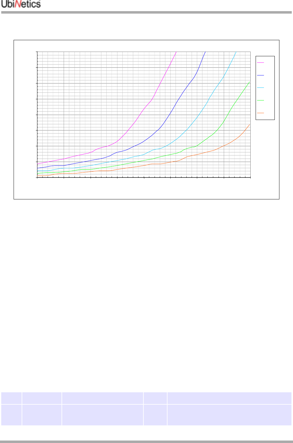
The relationship between cell ESR, usable battery capacity and minimum operating voltage
Power Sequencing
When the power is first applied, the module is held in reset until the input voltage rises above the
undervoltage lockout threshold of 3.2V.
At this point, the module enters Power-on state (as opposed to Switch-on state): only the UPR
(uninterrupted power) internal rail is powered. Current consumption is less than 150µA.
The On/Off pin is monitored by a small hardware state machine, which will commence the switch-on
sequence when a falling edge is detected on the power On/Off pin. If the power On/Off pin is not held low
for at least 50ms, the switch-on sequence is aborted.
If the On/Off pin is driven low for more than 50ms, the module enters Switch-on state, the main processor
resets, boots up and runs. After network registration, the current consumption will fall to 3.2mA, averaged
over 60 seconds. The RTC (real-time clock) will be reset only the first time this state is entered. Toggling
between Switch-on and Switch-off states will not clear the RTC.
If the On/Off pin is driven low for more than 50ms again, the module enters Switch-off state, with only the
RTC and alarm timer running. Current consumption in this mode is less than 150µA. Wake-up interrupts
may be programmed using the RTC if required.
If at any time, the main input voltage falls below 2.8V (nominal), and the main input voltage is below the
backup battery voltage, then the module enters backup mode. This is identical to switch-off state except
that any attempt to switch on will be blocked. The module will exit backup mode if either of the two defining
conditions (above) are lifted.
Power ON/OFF line
PIN Pin Name Description DIR Electrical Specification
32 ON/OFF External PSU Enable IN VIH = Vbatt ±200mV
VIL = 0V ±300mV
talk time usage of Li-ion battery capacity, with respect to cell internal resistance
0.0%
5.0%
10.0%
15.0%
20.0%
25.0%
30.0%
35.0%
40.0%
2.90 2.95 3.00 3.05 3.10 3.15 3.20 3.25 3.30
minimum operating voltage of module in full power call
battery capacity remaining when call dropped
250mR
225mR
200mR
175mR
150mR
Hardware Specification
GM40x GSM/GPRS Module Reference: UNDOC00048rF 16 of 176
On/Off Input Circuit
The power On/Off pin should be used to power up the module. This is achieved by pulling the line low for
more than 50ms (typically 60ms), then high again.
To power down the module, pull the line low for >600ms (typically 700ms). In order to avoid confusion, it is
recommended that the module be switched off using the AT+POWER_DOWN command. The VDDS line
may be used to monitor the power state of the module: it is high if the module is powered up, and low
otherwise.
RESET line
When the hardware RESET line is asserted the digital baseband chip is immediately reset, including the
background functions such as Real Time Clock.
Deasserting RESET causes low-level initialisation of this chip to occur. If the module was in the Switch-ON
state (see “Power Sequencing” on page 15) prior to the reset it will return to the Switch-ON state (but not in
call). If it was previously in the Switch-OFF state it will remain so.
Note however that the immediate nature of hardware RESET may potentially confuse the network if there is
an active GPRS PDP context at that time (because this is only cleared when deactivated or with a GPRS
detach). Also, data corruption could occur if it is asserted while writing to the SIM card or to the memory
chip. Hence, hardware RESET should only be used if absolutely necessary—the "AT+POWER_DOWN"
command (see “+POWER_DOWN Power Down Module” on page 168) or the ON/OFF line should be used
to power off if at all possible.
If the motherboard PCB is not shielded from the Antenna RF radiation, it is advisable to add a 33pF
decoupler to the Reset and ON/OFF lines as close as possible to the module connector.
PIN Pin Name Description DIR Reset active Reset not active
34 RESET External reset pin IN Vin >1.5V Vin <0.5V
Vbatt
10k
ON/OFF
2.8V
PWRONRST
100k
47k
10k
RESET
Hardware Specification
17 of 176 GM40x GSM/GPRS Module Reference: UNDOC00048rF
VDDS rail
This rail is intended to power external level-shifters, if these are required. It also gives a reliable indication
of whether the module is powered up or not. The output is high only if the module is in the "Switch-on"
state, as defined above.
2.2.6 Backup power supply
The module has provision for a backup supply, to power the RTC (real-time clock) when the module is
powered down. This is principally intended to be a double layer supercapacitor. Power is drawn from the
backup battery when the main supply voltage is both below 2.8V (nominal) and below the backup voltage.
There is a simple charging facility within the module, whereby a 3.2V (nominal) regulator may be
connected to Vbackup by setting a control register bit. Charging current is kept low, and the capacitor will
be fully charged within a few minutes. Hold-up time with the part shown is at least ten minutes.
Additional specifications for Vbackup:
PIN Pin Name Description DIR Electrical
specification Note
50 VDDS Power supply for external level shifter OUT 2.9V nominal
2.7V minimum
3.1V maximum
<10mA to be drawn
PIN Pin Name Description DIR Electrical
Specification Note
7PWR_RTC Back up power for RTC SUPPLY 3.0V - 5.5V
Min Typical Max Notes
Charge voltage 3.0V 3.2V 3.6V Icharge = 10µA
Charge current (µA) 250 500 800 Vbackup = 2.8V
Voltage at which module enters
backup mode 2.6 2.8 2.9 1
Backup current consumption
(µA) 50 150 2
Minimum back-up voltage 2.3 3
100n
<3R
100k 100k
2V8
Vext-en
Vext
supercapacitor
0.047F
charge 3.2V
Vbackup
e.g. Tokin FC0H473ZTBR24
1k
Hardware Specification
GM40x GSM/GPRS Module Reference: UNDOC00048rF 18 of 176
2.2.7 SIM Interface
The SIM interface conforms to ISO 7816-3 Class B (3V SIM interface).
The SIM Interface circuit
Capacitance on SIM interface lines
The SIM interface specification demands fast rise times for the clock, data and reset signals. This
precludes the use of ordinary-type varistors for ESD protection, as the typical capacitance of these parts
is 90-200pF. Several low-capacitance ESD protection devices are available from different manufacturers,
and these should be used.
1.Main supply must also be below backup supply before switchover will occur
2.This figure may be revised; it cannot exceed 150µA. Backup mode = 1 (lowest power mode)
3.This figure is not explicitly specified, so may be revised. Backup mode = 1 (lowest power mode)
PIN Pin Name Description DIR Default
State Min Max @ IO
21 SIM_VDD SIM power
supply OUT 02.7 3.3 6mA
PIN Pin Name Description DIR Default
State VOH min. VOL max @ IO
23 SIM_I/O SIM Data I/O 0See
footnote1
1.Output high voltage VOH is determined by 6k8 pull-up and leakage, ≅SVDD
0.4V 1mA
25 SIM_CLK SIM Clock OUT 00.7 SVDD 0.2 SVDD 20µA
27 SIM_RST SIM Reset OUT 00.8 SVDD 0.2 SVDD 200µA
SIMCLK SIMRST SIM_I/O Unit
Measured module capacitance 15.4 45 7.7 pF
Typical driver output impedance 52 2634 6800 Ω
all reqd
reqd
100n
GND
I/O
RST
CLK
VDD
SIM contacts
SIM_VDD
SIM_I/O
SIM_RST
SIM_CLK
33p main processor
33p
3V
6k8
10
400
2700
50
VPP
On host PCB
Hardware Specification
19 of 176 GM40x GSM/GPRS Module Reference: UNDOC00048rF
Allowable SIM line capacitances (typical)
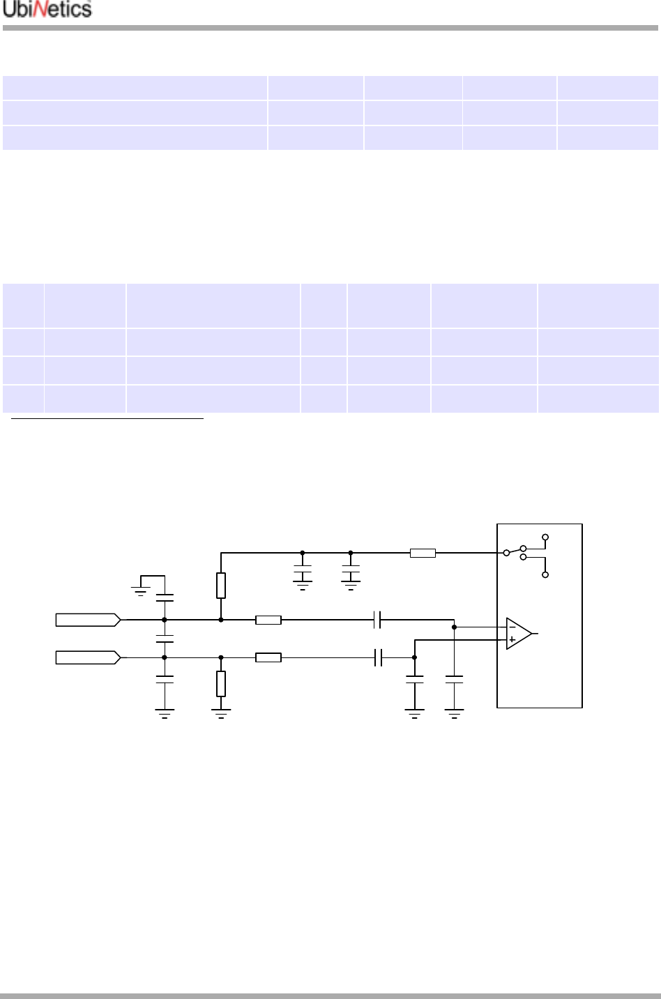
2.2.8 Audio Interface
Main microphone
Main microphone input circuit
Required risetime 50 1000 1000 ns
Margin by which specs are to be met 20% 20% 20% %
Allowable gross capacitance 350 138 53 pF
PIN Pin Name Description DIR
DC
condition1
1.DC conditions assume an electret microphone capsule with a DC resistance of ~4kΩ when biased at 1.5V across the
terminals, and a micbias supply of 2.5V. There is DC on these pins.
Digital clipping
level Input impedance
8AGND Microphone 1 Ground2
2.Cable screening, if used, should be grounded at this point.
10 MIC1P Microphone 1 Positive3
3.Clipping level is shown with programmable gain trim amplifier set to 0dB. Available range is -12dB to +12dB in 1dB steps
IN 2.0V 32.5mV RMS 1.2kΩ
12 MIC1N Microphone 1 Negative4
4.Differential input impedance is 1.2kΩ.
IN 0.5V 32.5mV RMS 1.2kΩ
2.0V
2.5V
MICBIAS supply
47p 2u2
1k
1k2
1k2
MIC AMP
CODEC chip
10n10n
100n
100n
33p
1k
1k
33p
33p
MIC1P
MIC1N
Hardware Specification
GM40x GSM/GPRS Module Reference: UNDOC00048rF 20 of 176
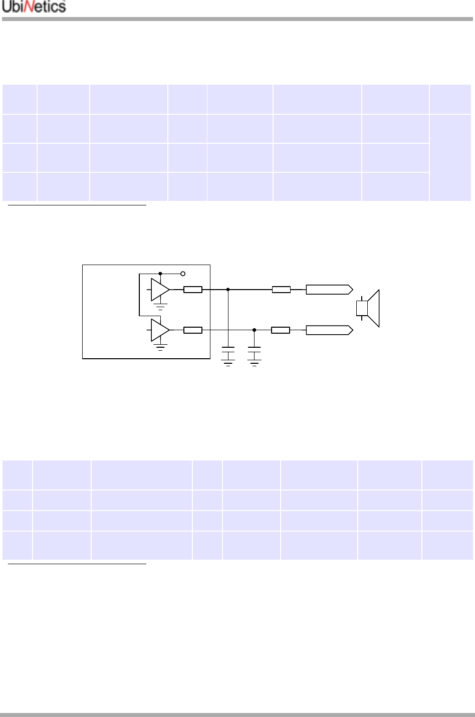
Main speaker
Main speaker driver circuit
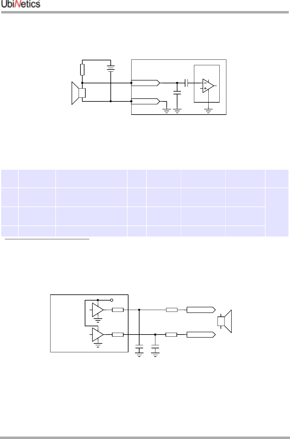
Auxiliary microphone
The auxiliary microphone input is primarily intended for an external headset. Great care must be taken to
ensure that the unbalanced signal input is not corrupted with TDMA noise. The grounding of the external
bias generator must be as shown below. The bias voltage and resistance will vary according to the
microphone capsule specification: indicative values are shown.
PIN Pin Name Description DIR DC
condition Clipping level Output
impedance Notes
9SPK1P Earphone 1
Positive OUT 1.25V 2Vpp 5Ω typical 1 2 3
1.Differential Maximum capacitive load at EARP-EARN = 100pF max
2.Common Mode Minimum resistive load at EARP or EARN = 200kΩ typical
3.Clipping level is equivalent to two rail-to-rail outputs each driven 3.6Vpp, in antiphase
11 SPK1N Earphone 1
Negative OUT 1.25V 2Vpp 5Ω typical
9 &
11 SPK1N/P As Bridge-tied
load OUT 0V 4Vpp 10Ω typical
PIN Pin Name Description DIR DC
condition Digital clipping
level Input
impedance Notes
14 AUXI Auxiliary Microphone IN N/A 365mV RMS 220kΩ1 2 3
1.AUXI programmable gain amplifier set to minimum (4.6dB gain)
2.Clipping level is shown with programmable gain trim amplifier set to 0dB, available range is -12dB to +12dB in 1dB step
3.Input impedance is normally defined by the external bias resistor, typically 2kΩ.
24mV RMS 220kΩ4 2 3
4.AUXI programmable gain amplifier set to maximum (28.2dB gain)
16 AGND For use with AUXI
input
+
+
3.6V
33p 33p
EARP
EARN
4R7
4R7
CODEC chip
0.3
0.3 32
Hardware Specification
21 of 176 GM40x GSM/GPRS Module Reference: UNDOC00048rF
Note that ESD protection will be required if these lines are accessible to the user.
Auxiliary microphone input showing external biasing requirement
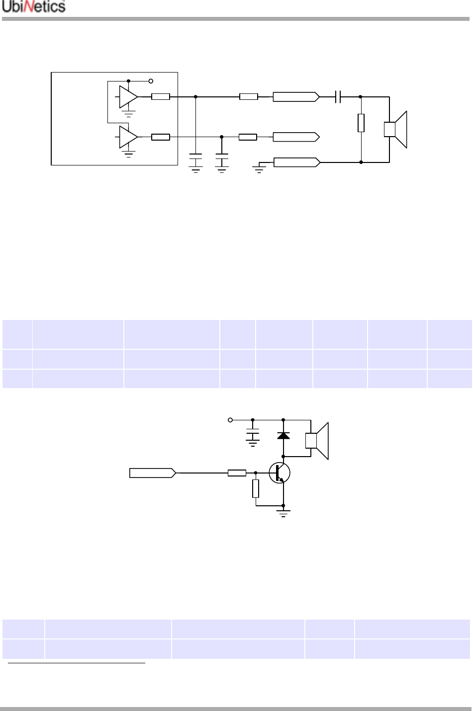
2.2.9 Auxiliary speaker
Auxiliary output circuit - bridge-tied load
PIN Pin Name Description DIR DC
condition Clipping level Output
impedance Notes
13 SPK2P
AUXOP Auxiliary Earphone
positive OUT 1.25V 1Vpp 50Ω typical 1 2 3 4
5
1.Clipping level is equivalent to two rail-to-rail outputs each driven 1Vpp, in antiphase
2.Differential Maximum capacitive load at SPK2P - SPK2N = 100pF maximum
3.Common Mode Minimum resistive load at SPK2P or SPK2N = 200kΩ typical
4.Minimum output resistive load at AUXO-AUXON = 1.2kΩ typical, 1.0kΩ minimum, i.e. auxiliary speaker must be greater
than 1kΩ impedance - to be confirmed
5.Maximum output swing at AUXOP-AUXON: 5% distortion maximum. Load = 1kΩ = 1.96Vpp typical, 1.6Vpp minimum
15 SPK2N
AUXON Auxiliary Earphone
negative OUT 1.25V 1Vpp 50Ω typical
Wired as bridge-tied load OUT 0V 2Vpp 10Ω typical
AUXin
AGND
MODULE
100n
33p
+
codec
+mic bias
2V
2k
MIC
+
+
3.6V
33p 33p
SPK2P
SPK2N
4R7
4R7
CODEC chip
0.3
0.3 1k
Hardware Specification
GM40x GSM/GPRS Module Reference: UNDOC00048rF 22 of 176
AUX output using 3-wire headset
Note the inclusion of a 1kΩ resistor to avoid loud "pops" in the earphone when the headset is plugged in.
The value of the 22µF capacitor is chosen to pass 300Hz, and may be Tantalum or ceramic type.
The codec is designed for both differential and single ended use; however we recommend differential,
rather than single-ended mode, to keep TDMA noise to a minimum. It can be difficult to screen out the
TDMA noise using the analogue ground as the return.
Sounder output
Sounder implementation circuit
The sounder output generates a modulated frequency, programmable between 349Hz and 5276Hz with
12 semitones per octave. The output amplitude is also programmable.
Analogue input
PIN Pin Name Description DIR Output
level Min Max @ IO
38 SOUNDER To drive buzzer OUT VOH 0.8*VDDS 2mA
VOL 0.22*VDDS
PIN Pin Name Description DIR Internal name
17 AUXV0 Analog Input1 2
1.The ADC will output all “1”s for an input voltage of 7V nominal.
2.The input pin is not designed to take more than 5.5V.
IN VBAT_MEAS
1k
AGND
22uF
+
+
3.6V
33p 33p
SPK2P
SPK2N
4R7
4R7
CODEC chip
0.3
0.3
32
100n 22
Vbatt
SOUNDER
47k
470

Hardware Specification
23 of 176 GM40x GSM/GPRS Module Reference: UNDOC00048rF
This input is intended to be used for battery voltage measurement, which in the case of Lithium-ion
batteries, can form a reasonably accurate remaining capacity estimate. Each discrete step in the A/D
reading represents approximately 1.5% of the capacity of a typical Lithium-ion battery.
Battery measurement ADC Electrical Specification
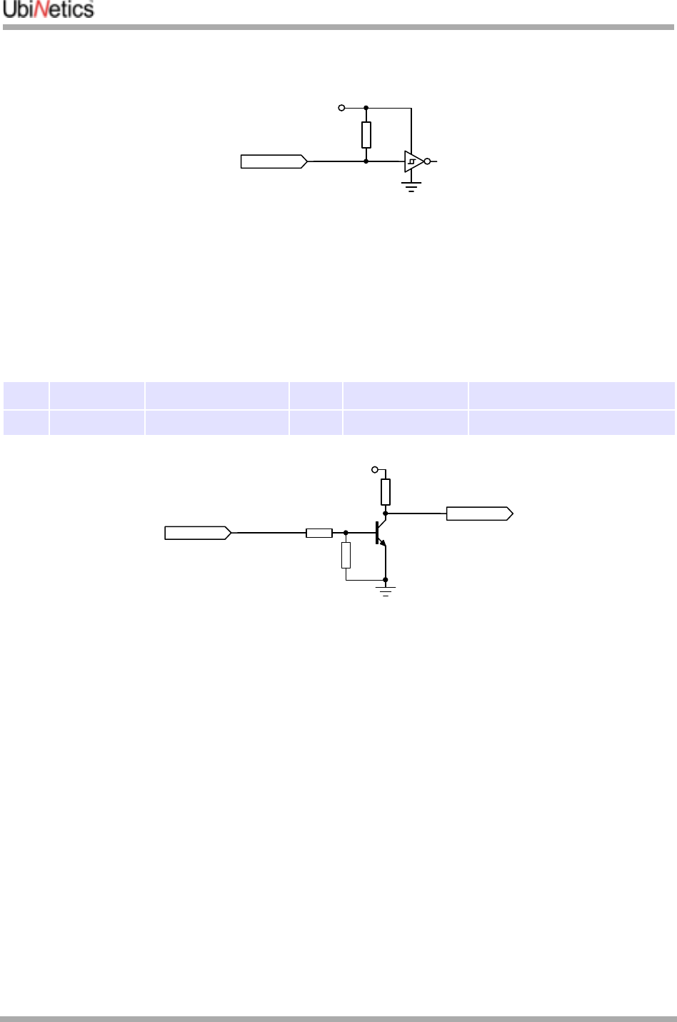
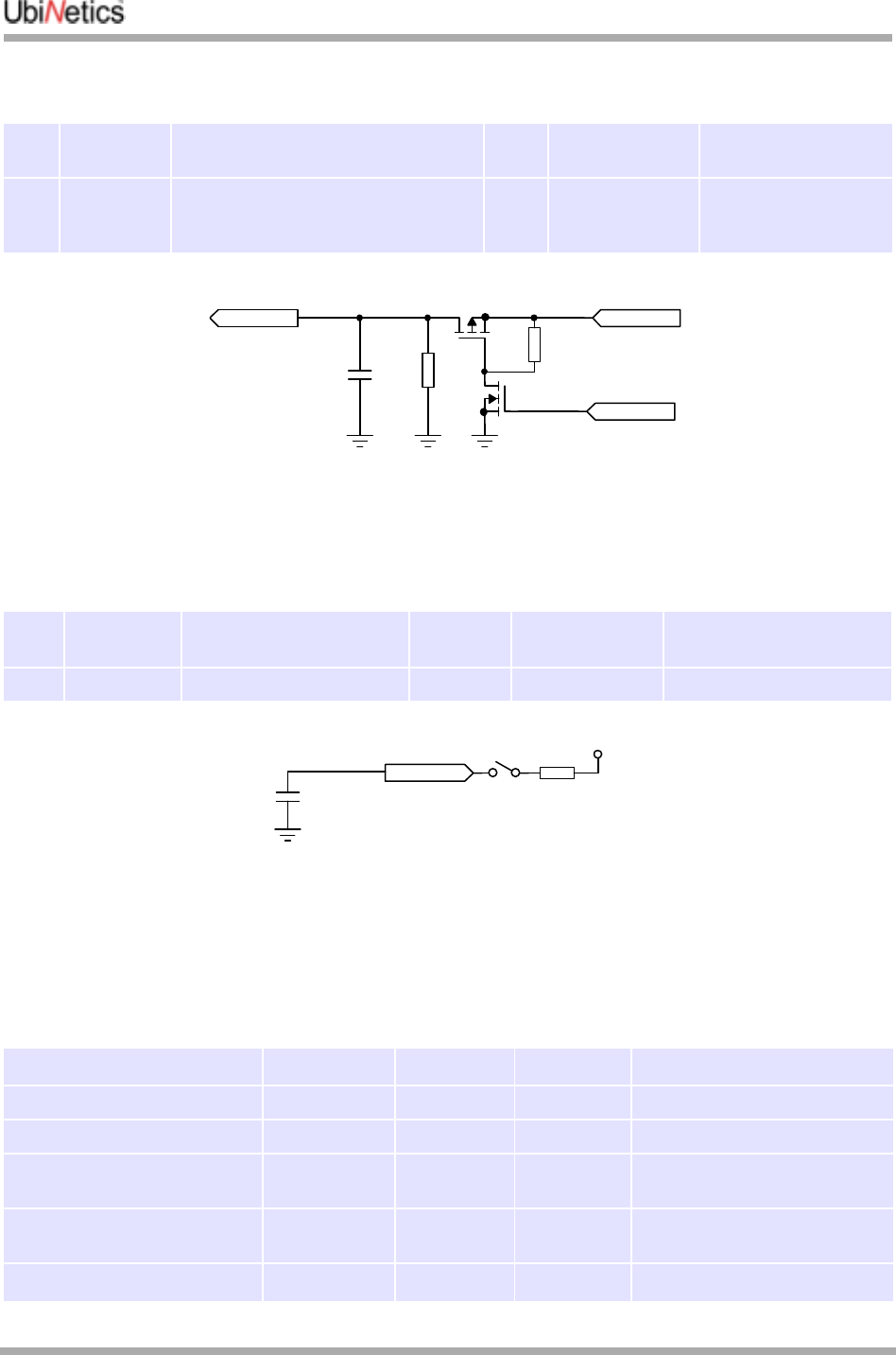
2.2.10 Digital I/O
Host Status
This pin allows the host to be asleep whilst the module is still attached to the network. The host indicates
that it is entering suspend mode by taking HOST_STATUS low. The module then inhibits data transfer until
HOST_STATUS goes high.
In order to ensure no data is lost in the entry to suspend mode, a specific sequence of checks is required:
these are detailed in the software specification.
If this pin is not used, connect a 10kΩ resistor between this pin and VDDS (pin 50).
Parameter Condition Min Nom Max Unit
AUXV0 input
voltage range 5.5 V
Sample acquisition time 16.5µs delay
8µs acquisition 24.5 µs
Sampling Rate 2.17 Samples/s
Resolution 10 Bit
Battery Voltage
Measurement Step size Tolerance indicates
ADC Linearity, and is
not cumulative
-5% 6.8 +5% mV
Reference Voltage
Tolerance Temperature drift is
50ppm/°C-0.5% +0.5%
AUXV0 input impedance 10 MΩ
AUXV0 to ADC input
attenuation 0.25 V/V
Integral non linearity Best fitting -1 +1 LSB
Differential non linearity -1 +1 LSB
PIN Pin Name Description DIR Notes
44 HOST_STAT Host Status IN See “Standard CMOS logic levels” on page 26

Hardware Specification
GM40x GSM/GPRS Module Reference: UNDOC00048rF 24 of 176
Host Wakeup
Active high output. If the host is asleep, and an incoming call is received, or data, or SMS, then the host
wakeup pin is driven high for 20µs in order to wake up the host.
Because the AT command interface is host driven, there is no way for the module to output unsolicited
data. This interrupt indicates that the module has some message to convey, and would like to be
questioned. This is not used by the standard AT command set, only by additional functions programmed
into the module by the customer.
2.2.12 Keyboard Interface
PIN Pin Name Description DIR Notes
36 HOST_WAKEUP Alert host of
incoming call/data OUT See “Standard CMOS logic levels” on page 26.
2mA rated
2.2.11 Interrupt Output
PIN Pin Name Description DIR Notes
46 INT_OUT Interrupt Output OUT See “Standard CMOS logic levels” on page 26
PIN Pin Name Description DIR Notes
29 KBC0/GPO0 Keyboard Column 0 OUT COLUMN (A6) See “Standard CMOS logic
levels” on page 26.
2mA rated.
All row inputs have a 27kΩ
(nominal) pull-up resistor
integrated within the IC.
Every key can generate a
keyboard interrupt.
31 KBC1/GPO1 Keyboard Column 1 OUT COLUMN (A5)
33 KBC2/GPO2 Keyboard Column 2 OUT COLUMN (B5)
35 KBC3/GPO3 Keyboard Column 3 OUT COLUMN (D5)
37 KBC4/GPO4 Keyboard Column 4 OUT COLUMN (E5)
39 KBR0 Keyboard Row 0 IN ROW(A4)
41 KBR1 Keyboard Row 1 IN ROW(B4)
43 KBR2 Keyboard Row 2 IN ROW(D5)
45 KBR3 Keyboard Row 3 IN ROW(B3)
47 KBR4 Keyboard Row 4 IN ROW(A2)
2.2.13 Asynchronous Serial Interface
Pin names used are those for DCE device:
PIN Pin Name Description DIR Notes
40 CTS Clear to send (to host) OUT See “Standard CMOS logic levels” on page 26.
4mA rated.
CTS and RTS active LOW.
Serial data rate 56Kbps (57600bps)
42 TXD Transmit Data (from host) IN
48 RTS Request to send (from host) IN
49 RXD Receive Data (to host) OUT

Hardware Specification
25 of 176 GM40x GSM/GPRS Module Reference: UNDOC00048rF
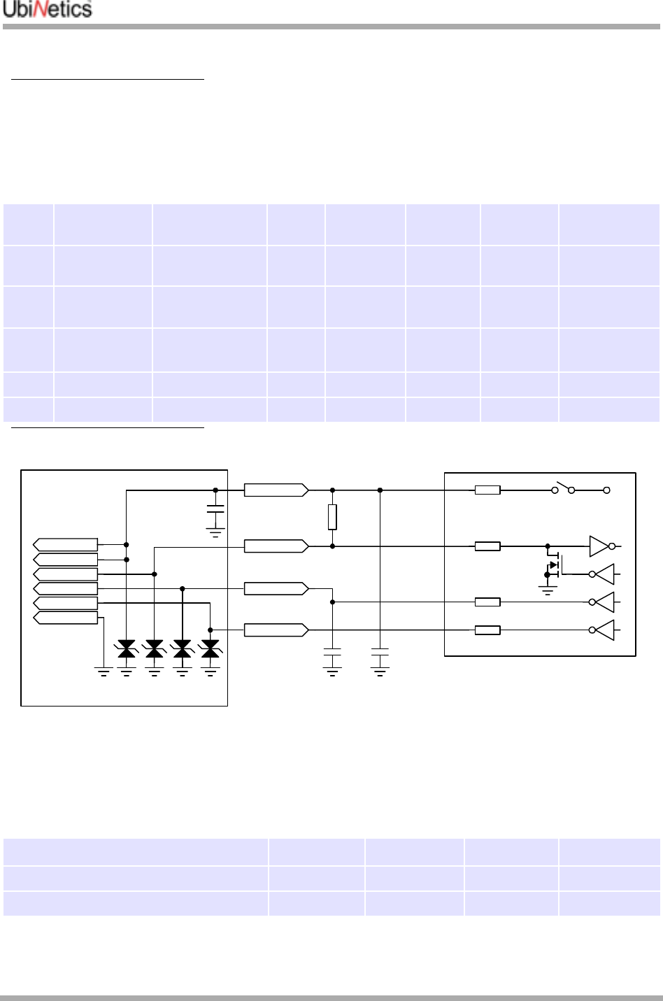
2.2.14 General Purpose I/O
2.2.16 RF Interface Specification
The RF Connection Pads incorporate a signal and ground PCB pad for soldering a semi-rigid coaxial
cable as an interface to the host platform. The pads are also used for RF probing during production test.
2.2.17 Termination of unused lines
If the host design does not require them, unused lines can be terminated as follows:
●SPI bus (pins 18, 20, 22, 24 and 26): leave unconnected
●GPIO1, 2 and 3 (pins 19, 28 and 30): leave unconnected
●Host_wakeup (pin 36): leave unconnected
●Host_status (pin 44) and VDDS (pin 50): connect 10KΩ resistor between the two pins
●Keyboard matrix (pins 29, 31, 33, 35, 37, 39, 41, 43, 45, 47): leave unconnected.
PIN Pin Name Description DIR Notes
28 GPIO1 General purpose I/O I/O See “Standard CMOS logic levels” on page 26.
30 GPIO2 General purpose I/O I/O
19 GPIO3 General purpose I/O I/O
2.2.15 Synchronous Serial Interface
PIN Pin Name Description DIR Notes
18 SPI_DATA Serial Data OUT See “Standard CMOS logic levels” on page 26.
20 SPI_CLK Serial Clock OUT
22 SPI_CS Chip Select OUT
24 SPI_D/C Data / Command OUT
26 SPI_RST Reset OUT
Parameter Specification Conditions
Output Impedance 50Ω Across GSM900, DCS1800 & PCS 1900
bands
Output Load Upper Limit 15:1 VSWR1, but Ipeak increases.
Ipeak meets specification at <5:1
VSWR
1.See “RF” on page 37 for the affects on performance of different VSWRs.
To maintain PA stability
Output Power GSM 900: 33dBm ±2dBm (full power)
GSM1800: 30dBm ±2dBm (full power)
These and other power control levels
are compliant with ETSI 11.10 Section
13.3
Units are calibrated to allow for a fixed
attenuation from the RF output of the module
to the antenna port.
The loss should not exceed 0.4dB and is
specified to within ±0.1dB.

Hardware Specification
GM40x GSM/GPRS Module Reference: UNDOC00048rF 26 of 176
2.3 Electrical Specification
2.3.1 Standard CMOS logic levels
Parameter Description Min Nom Max Unit
VDDS I/O supply voltage 2.7 2.9 3.1 V
VIH High level input voltage 0.7*VDDS VDDS+0.5 V
VIL Low level input voltage -0.5 0.3*VDDS V
VOH High-level output voltage 0.8*VDDS V
VOL Low-level output voltage 0.22*VDDS V
IOL/LOH Rated output current 2mA
Multiplexer
27 of 176 GM40x GSM/GPRS Module Reference: UNDOC00048rF
3.0 Multiplexer
3.1 Introduction
The multiplexer serial interface used by the UbiNetics GPRS module supports a number of different data
streams (GPRS data, circuit switched data / fax, AT command interface, control / status information etc.).
Some of these can potentially be in operation simultaneously and may be communicating with different
host applications and/or drivers. The UbiNetics Multiplexer provides the means of accessing these
different data streams on the various host systems.
The implementation provides a single multiplexed serial link based on GSM 07.10 / 3G TS 27.0101. This
supports operation on a wide range of hosts. Depending on the host platform and / or application, it may
be necessary to implement the multiplexer within a driver and expose standard interfaces (virtual serial
ports) for each of the data channels. Alternatively, in some cases where the GPRS module is used for a
dedicated application, it may be desirable to build the serial multiplexer into the application software.
3.2 Overview
The Multiplexer provides a means to transmit and receive multiple data streams over a single
asynchronous serial connection. It supports a number of virtual connections between software entities in
the host platform and the corresponding entities in the GPRS module. Communication across the
multiplexed link uses 8-bit characters arranged into frames delimited by flag bytes.
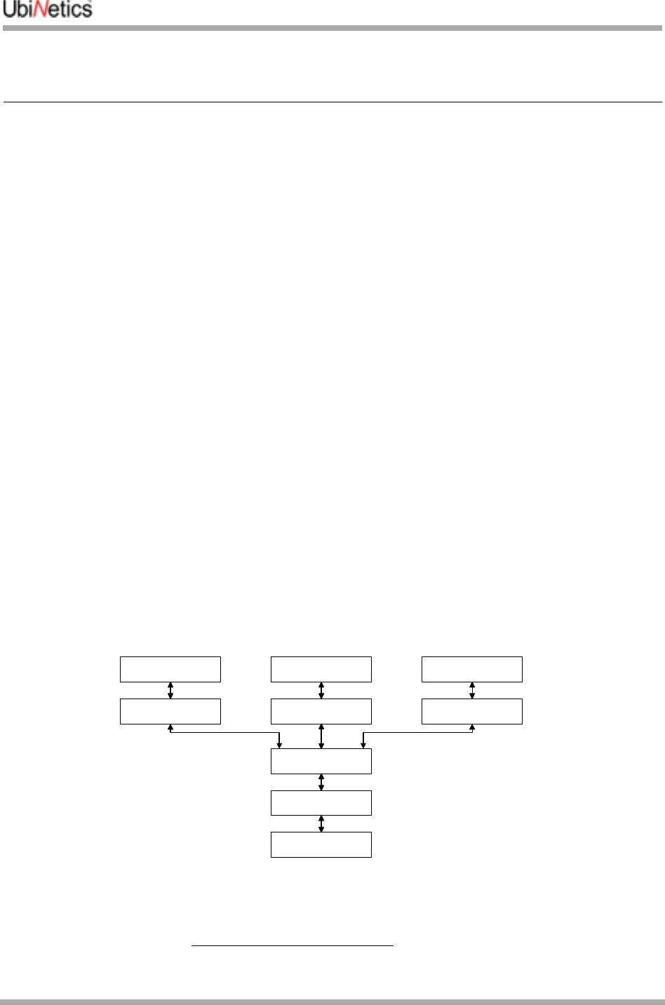
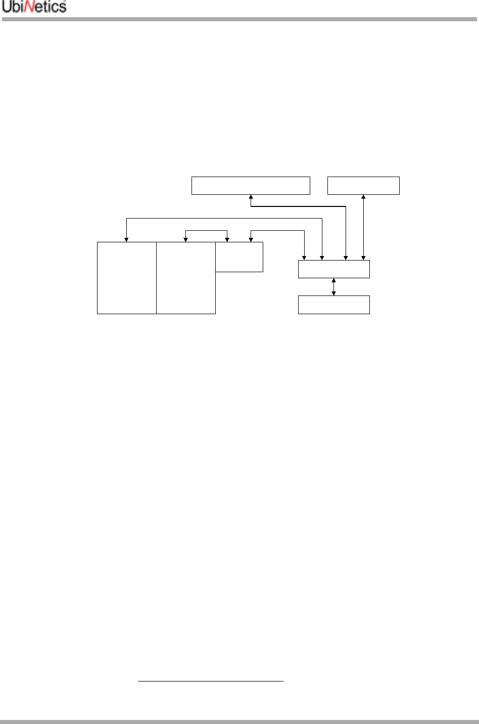
3.2.1 Software Structure
Possible Host Software Structure
1.ETSI TS 127 010 V3.3.0 (2000-03) Terminal Equipment to Mobile Station (TE-MS) multiplexer protocol (3G TS 27.010
version 3.3.0 Release 1999)
UART
Serial port driver
Multiplexer
Serial Port Emulation
(or private API)
Serial Port Emulation
(or network driver)
Serial Port Emulation
Modem Driver (DUN,
Fax etc) AT commands for
control / status etc
TCP/IP / PPP
(GPRS)
Multiplexer
GM40x GSM/GPRS Module Reference: UNDOC00048rF 28 of 176
Each of the top-level entities shown above is connected to a corresponding entity in the GPRS unit via one
of the multiplexer data channels (Data Link Connections / DLCs). These are set up one at a time, normally
on demand when a particular function is required.
GPRS Card / Module Software Structure
Initially each new DLC will connect to an instance of the AT command interpreter. The data channels are
connected to the other stack entities either by issuing the appropriate AT commands (e.g. dialling) or
explicitly using the multiplexer service negotiation command.
3.3 Supported Functions
The following functions of 3G TS 27.0101 are supported. Additional functionality may be added at a later
stage.
●Multiplexer Advanced option (flag byte transparency) without error recovery
●Multiplexer Start-up / Closedown
●Data Link Connection (DLC) Establish / Release
●Up to 6 user DLCs
●UIH frames for user data (Unnumbered Information with Header check only)
●Flow Control command
●Modem Status command
●Service Negotiation command
●Null convergence layer (unformatted data streams).
3.4 Implementation
For more information on the implementation details, see footnote 1. In particular, control field values and
bit allocations are not discussed here.
1.ETSI TS 127 010 V3.3.0 (2000-03) Terminal Equipment to Mobile Station (TE-MS) multiplexer protocol (3G TS 27.010
version 3.3.0 Release 1999)
UART / Driver
Multiplexer
GSM Stack
AT Command Interpreter
PPP
GPRS Stack
Trace / Debug (Test)
Multiplexer
29 of 176 GM40x GSM/GPRS Module Reference: UNDOC00048rF
3.4.1 General
Multiplexer Mode
The multiplexer operates using the advanced option without error recovery. This uses a flag transparency
mechanism to allow rapid resynchronisation in the event of any data loss.
Frame Structure
The frame used for the advanced option consists of an opening flag byte, address field byte, control field
byte, information field (variable or omitted depending on the frame type), frame check byte, and a closing
flag. The closing flag of one frame can be the opening flag of the following frame, so the minimum
overhead is 4 bytes per frame.
4.1.3 Supported Frame Types
Any other frame types are not currently supported.
Acknowledgements, Timeouts and Retries
Where a frame type has an associated acknowledgement, if the expected response frame is not received
within time T1 (default of 100ms) then the sender can retry up to a maximum of N2 times (default of 3).
Frame Check Sequence (FCS)
The frame check sequence uses an 8-bit CRC algorithm. This allows a simple look-up table based
implementation to be used (see1 for algorithm and examples).
3.4.2 Multiplexer Start-up
The GPRS module / card will always start up in non-multiplexed mode. Before the multiplexer is initialised
the serial data stream to / from the UART connects directly to the AT command interpreter. The system can
be operated exclusively in non-multiplexed mode but use of some functions may be restricted. Multiplexed
mode is started with the following sequence:
●Host issues the AT+CMUX command (see the referenced documentation2 for command syntax). If the
GPRS unit supports multiplexed operation and accepts the parameters issued with the command then
it will return an "OK" response.
●At this point both the host and the GPRS unit should switch baud rate to that specified in the issued
AT+CMUX command and also set any other parameters as per the command (see table below for
Frame Type Use
SABM (Set Asynchronous Balanced Mode) Establishing a control or data channel.
UA (Unnumbered Acknowledgement) 'OK' Acknowledgement to SABM or DISC frame.
DISC (Disconnect) Closing a data channel or closing down the multiplexer.
DM (Disconnected Mode) 'Already disconnected' response to DISC or UIH frame.
UIH (Unnumbered Information with Header Check) User data or multiplexer control command. Frame
check applied to header only.
1.ETSI TS 127 010 V3.3.0 (2000-03) Terminal Equipment to Mobile Station (TE-MS) multiplexer protocol (3G TS 27.010
version 3.3.0 Release 1999)
2.ETSI TS 127 007 V3.6.0 (2000-10), AT command set for User Equipment (UE) (3GPP TS 27.007 version 3.6.0 Release
1999)
Multiplexer
GM40x GSM/GPRS Module Reference: UNDOC00048rF 30 of 176
allowable parameter values). The default values will be used for any parameters which are not
included.
●The host should then send a SABM frame on DLC0. The GPRS module / PC card will respond with a UA
frame. Multiplexed mode is now active.
●Either end can now send commands on the control channel, or establish new user data channels. In
practice the establishment of new data channels will only be initiated by the host.
AT+CMUX Command parameters
3.4.3 Multiplexer closedown
The multiplexer is closed down by sending either a DISC frame on DLC0, or by using the closedown
command (see below). This can be sent from either end of the connection but would normally be sent by
the host. Whichever command type is used, any open data channels will be closed and the link will revert
to non-multiplexed AT command mode.
3.4.4 Data channel establishment and release
A data channel (Data Link Connection / DLC) is established by sending a SABM frame with the specified
DLCI. This will only be initiated by the host. If the DLC can be established then the GPRS unit will respond
by sending a UA frame with the same DLCI. If the DLC cannot be established then the response will be a
DM frame.
Once the data channel is established it is connected to one instance of the AT command interpreter in the
GPRS unit. All newly created data channels are equivalent until dedicated in some way. This can be done
in two ways - either by using the service negotiation command to explicitly define what the channel will be
used for, or implicitly by establishing a call, GPRS session etc.
The DLC is closed down by sending a DISC frame with the appropriate DLCI. If the DLC can be
disconnected then the GPRS unit will respond by sending a UA frame with the same DLCI. If the DLC is
already disconnected then the response will be a DM frame.
3.4.5 Data transmission
User data is transferred with UIH frames with the appropriate DLCI. The error recovery mode is not used,
so there is no acknowledgement of data receipt, and lost or bad frames are not retransmitted. In addition,
due to the use of UIH frames, there is no error check on the information payload, so if the connection is
Parameter Allowable values
Operation mode 1 (advanced option)
Subset (Frame Type) 0 (UIH frames only)
Port Speed 1-5 (9600 to 115200 baud) (default = current rate)
N1 (Maximum frame size) 31-64 (default = 64)
T1 (Acknowledgement Timer) 10-100 (default 10 = 100ms)
N2 (Maximum Retransmissions) 3-10 (default 3)
T2 (Response Timer) 30-120 (default 30 = 300ms)
T3 (Wakeup Timer) 3-20 (default 10s)
k (Window Size) Not supported - applies to error recovery mode only

Multiplexer
31 of 176 GM40x GSM/GPRS Module Reference: UNDOC00048rF
expected to be prone to errors then error checking (and correction if required) should be performed by
the higher layers.
Currently only type 1 (null) convergence layer is supported, so no structure is conveyed or implied in the
data. Any additional packet framing etc. required must be implemented with a higher-layer protocol.
Each data channel has an associated priority. The priority of a particular channel is based on the DLCI,
with lower DLCI values having higher priority. See the referenced documentation1 for the priority
assignments given to particular DLCI values. The multiplexer will attempt to transmit higher priority data
before that of lower priority. Frames already being transmitted will not be interrupted by higher-priority
frames. The multiplexer will interleave high and low priority data so as to prevent complete blocking of low-
priority data channels, while giving precedence to higher-priority data.
3.4.6 Control channel commands
The multiplexer control channel provides for various control commands and responses to be sent. These
are transferred using information frames (UIH) on DLC 0. Each control command frame consists of the
standard frame header etc. The information part of the frame contains a type byte which specifies the
command type and whether it is a command (C/R bit = 1) or a response (C/R bit = 0), a length byte, and a
variable number (may be zero) of value bytes containing the command parameters.
Each command has a corresponding response which has the same format as the command except for
the C/R bit mentioned above. The response should be sent as soon as possible after receiving the
command. If an unrecognised or unsupported command is received then a 'Non Supported Command
Response' should be sent.
If the expected response frame is not received within time T2 (default of 300ms) then the sender can retry
up to a maximum of N2 times (default of 3).
Multiplexer Closedown Command
The multiplexer closedown command is used to reset the link into normal AT command mode. This would
normally only be sent by the host. The GPRS unit will send the appropriate response and then return to
non-multiplexed mode.
Flow Control On / Off Command
The flow control commands are used to handle aggregate flow. Either end of the link can send a flow
control off command when it is unable to receive any new data. It should then send a flow control on
command when it is again ready to receive.
If a flow control off command is received then the multiplexer should not transmit any more user data. Any
new user data requests should be queued or failed. Command frames can still be transmitted as normal.
Modem Status Command
The modem status command is used to transfer virtual V.24 control signals associated with a data stream.
The following signals are supported:
1.ETSI TS 127 010 V3.3.0 (2000-03) Terminal Equipment to Mobile Station (TE-MS) multiplexer protocol (3G TS 27.010
version 3.3.0 Release 1999)
Modem Status Command Bit DTE >DCE DCE >DTE
RTC (Ready to communicate) DTR DSR

Multiplexer
GM40x GSM/GPRS Module Reference: UNDOC00048rF 32 of 176
The exact mapping of these signals is detailed in the referenced documentation1, section 5.4.6.3.7.
The break signal is not supported. The EA bit of the control signal octet should always be set to 1 and the
command length should always be 2.
Service Negotiation Command
The service negotiation command is used to specify what a particular data channel will be used for. This
allows the GPRS unit to direct incoming call notifications etc. to the appropriate channel. The command
frame contains two value bytes — the first defines the general service type (voice or data) and the second
defines the specific service.
Further data types may be added. These will continue as above using sequential values in the V1-V7 bits.
If the service negotiation command is not sent, the data channel will default to the normal AT command
mode. If there is no data channel specified for a particular service type, it is intended that incoming call
notifications for that service be sent on all open data channels which are in the AT mode. Contact
UbiNetics for more information about this.
RTR (Ready to receive) RFR(RTS) CTS
IC (Incoming call) 0RI
DV (Data valid) 1DCD
1.ETSI TS 127 010 V3.3.0 (2000-03) Terminal Equipment to Mobile Station (TE-MS) multiplexer protocol (3G TS 27.010
version 3.3.0 Release 1999)
Service Value Byte Specific Service Byte Data type
03 (S2=0, S1=1, EA=1) 01 (V1-V7=0, EA=1) Normal AT command mode (unspecified data type)
03 03 (V=1) Circuit-switched data
03 05 (V=2) GPRS data
03 07 (V=3) Trace / Debug output
05 (S2=1, S1=0, EA=1) Any Voice (not supported)

Host suspend procedure
33 of 176 GM40x GSM/GPRS Module Reference: UNDOC00048rF
4.0 Host suspend procedure
4.1 Introduction
When the GPRS module is used with a PDA host, it is necessary for the host to be able to suspend
operations due to user command or inactivity timeout, while keeping the module active. It is also
necessary for the module to be able to bring the host out of suspend mode on certain events. This section
describes the procedure that is used to enter and exit host suspend mode.
4.2 Multiplexer
The module contains a serial multiplexer based on the GSM 07.10 specification. However, the module
starts in non-multiplexed mode and so it is necessary to have procedures for entering and exiting
suspend mode which do not depend on the multiplexer.
The multiplexer specification includes a sleep mode which can be entered into by one party sending a
sleep mode request to the other. Also it defines a wake-up procedure of sending flag bytes until a
response is received. In theory these could be used to handle the host suspend mode, but since these
would only work if the multiplexer were active, another method has been defined which works in non-
multiplexed mode also.
4.3 Module power modes
One feature of the module is its ability to conserve power by turning off the 13MHz system clock (deep
sleep mode). The deep sleep manager in the module always tries to put the module into deep sleep mode
by regularly checking if deep sleep can be enabled.
The conditions for entering deep sleep mode are:
●There is no activity required on the air interface for a number of frames
●There are no timers about to expire
●There are no tasks ready to run
●There has been no activity on the UART Rx, Tx and flow control lines for 30 seconds
●There is no SIM activity
●The backlight is not active.
Deep sleep mode will be exited when:
●The defined sleep period has expired (e.g. for air interface or timer)
●There is an interrupt
●The UART exits sleep mode due to a transition on the Rx or CTS line.
The UART exiting sleep mode and the 13MHz clock starting takes some time. The host does not know
when the module is in deep sleep mode, so it is possible that the first character sent to the module (which
causes it to exit deep sleep mode) after some time could be lost.
To avoid this, the CTS flow control line is toggled prior to sending an AT command or multiplexer packet if
no characters have been sent for some time.

Host suspend procedure
GM40x GSM/GPRS Module Reference: UNDOC00048rF 34 of 176
4.4 Host wake-up events
The module provides the following wake-up events that will cause the HOST_WAKEUP output to be
toggled:
●Incoming circuit switched call
●SMS received
●GPRS data received
●UART Tx buffer >half full.
The MMI API allows for the first three of these events to be selectively enabled or disabled. The default
state is that all events are enabled.
The events will only generate a pulse on the HOST_WAKEUP line if they happen while the host is
suspended, or within a fixed time window before the host is suspended. This latter case is to guard
against the possibility of losing an event that happens after a suspend operation has been committed to
but before the host is suspended.
4.5 Host suspend operation
The host indicates that it is entering suspend mode by taking HOST_STATUS low. The module then inhibits
data transfer until HOST_STATUS goes high. In order to ensure no data is lost in the entry to suspend
mode, a specific sequence of checks is required.
Host suspend is normally disabled. It can be enabled by the AT command AT+HOST_STATUS (or from the
MMI API).
4.5.1 Host suspend procedure
The following procedure should be adopted by the host when suspending:
●Turn off all unsolicited responses (e.g. +CREG etc.)
●Terminate any circuit switched data calls
●Mask the HOST_WAKEUP interrupt within the PDA
●Take the HOST_STATUS output low
●Continue to read serial characters from the UART into a buffer for at least one character period after
HOST_STATUS is taken low
●Suspend (unmasking HOST_WAKEUP interrupt).
4.5.2 Module wake-up behaviour
The module acts as follows:
●If HOST_STATUS is low, no characters are sent to the UART (equivalent of CTS flow control, but
inverted)
●If a wake-up event is detected and HOST_STATUS is low, the HOST_WAKEUP output is toggled high
then low for approximately 20µs
●If a wake-up event is detected and HOST_STATUS is high, a timer is started (or re-started if already
running)
●When the timer expires, if HOST_STATUS is high, no action is performed. If HOST_STATUS is low the
HOST_WAKEUP output is toggled high then low approximately 20µs. This ensures that a wake-up
event that occurred just before or during the suspend operation is correctly serviced.
Host suspend procedure
35 of 176 GM40x GSM/GPRS Module Reference: UNDOC00048rF
4.5.3 Host wake-up behaviour
The host acts as follows:
●The HOST_WAKEUP pulse causes the host to exit the suspend state
●When it is ready to receive serial characters from the module, the host sets HOST_STATUS high
●Toggle CTS high and low briefly to force module to wake-up and check HOST_STATUS.
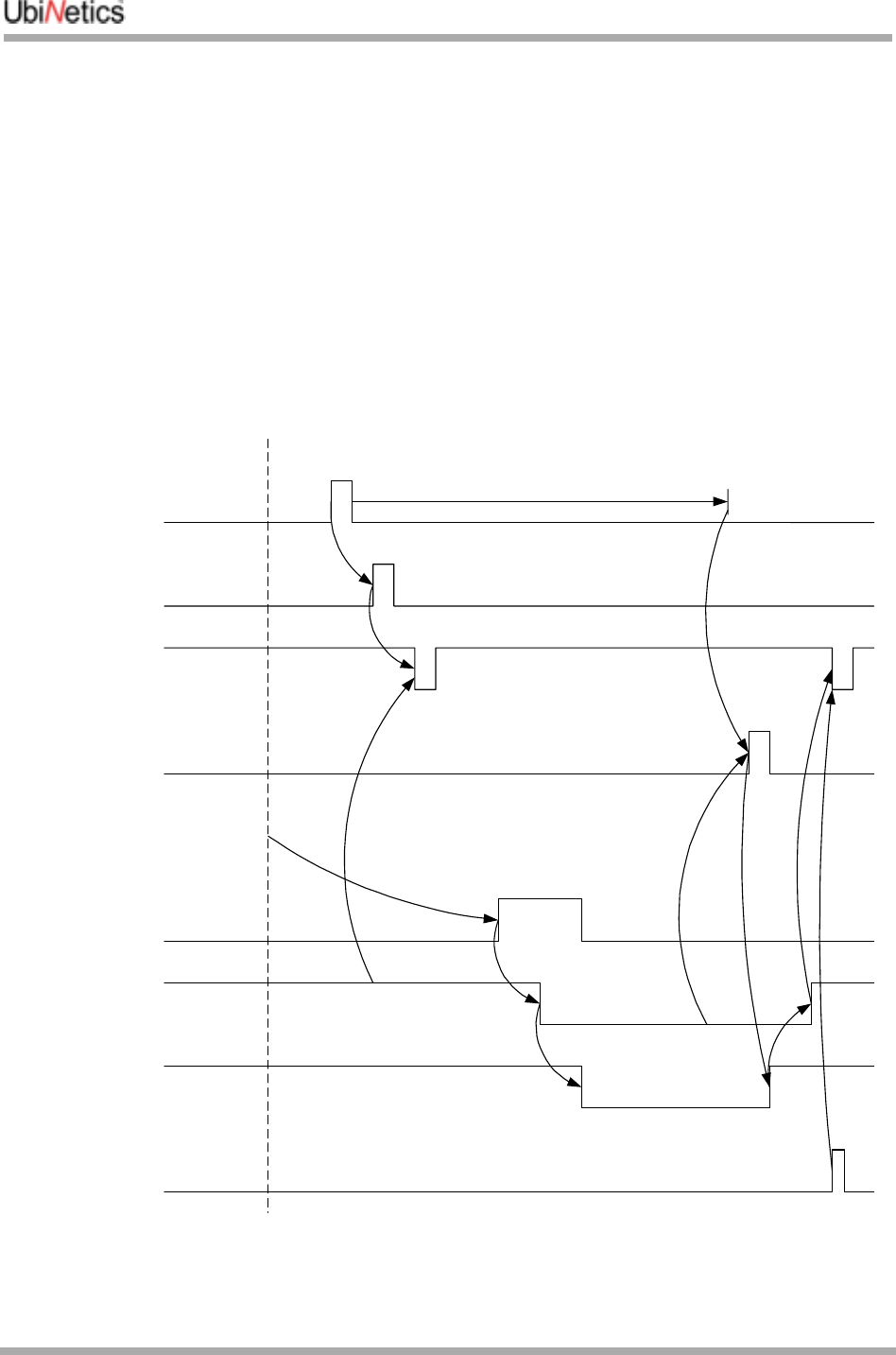
4.5.4 Timing diagram
The following diagram shows the behaviour in the worst-case scenario of a wake-up event occurring
during the suspend procedure:
The wake-up event happens after the host has committed to the suspend procedure and cannot abort it.
Since HOST_STATUS is high, the module starts a timer. It also starts to output the serial string
corresponding to the event (e.g. “RING”). The diagram show the case where the first character is
Event
Data ->UART
driver
UART TxD
IRQ MASK
Suspend
committed
HOST_WAKEUP
HOST_STATUS
!SUSPEND
HOST
MODULE
Timer
CTS

Host suspend procedure
GM40x GSM/GPRS Module Reference: UNDOC00048rF 36 of 176
transmitted before HOST_STATUS goes low, and the remainder of the string is transmitted after the host is
woken again. The HOST_WAKEUP pulse is generated after the timeout as HOST_STATUS is low at that
point. This causes the host to wake up again and receive the rest of the string corresponding to the wake-
up event.
This procedure ensures that a wake-up event always causes the host to wake up, but does have the
possibility of generating a wake-up when the host has already accepted the event just prior to
suspending.

Integration Guidelines
37 of 176 GM40x GSM/GPRS Module Reference: UNDOC00048rF
5.0 Integration Guidelines
The following notes are designed to provide general help to those considering integrating the GM400 or
GM401 modules into their product.
When designing a product incorporating a GM400 or GM401 module, the main issues to consider are:
●RF
●EMC
●Ground plane connection
●Power supply
●Mechanical
●Firmware upgrading.
5.1 RF
Receiver sensitivity and transmitter output are greatly affected by the design of the RF connection. Great
care should be taken with the RF connection in the final product, as the VSWR and insertion losses in the
connection to the terminals can reduce transmitter and receiver performance, and increase current
consumption.
5.1.1 Receiver
VSWR
The input impedance of the receiver is 50Ω. In order to obtain the maximum power transfer and therefore
highest sensitivity, the antenna and any connecting cables should present an impedance as near to 50Ω
as possible.
The table below shows how the VSWR effects sensitivity:
Any reduction in sensitivity can be minimised by careful selection of an antenna suitable for the
application. A list of suppliers who may be able to help you with this is provided at the end of the section.
It may be necessary to add an external (to the module) matching network in order to ‘tune’ the antenna to
50Ω.
Insertion Loss
The insertion loss of any cables and matching circuit will cause dB for dB a loss in the sensitivity of the
completed product. It is therefore important to minimise this as much as possible by
●using high-Q components
VSWR Reduction in Sensitivity
1:1 0 dB
1.5:1 0.18dB
2:1 0.51 dB
3:1 1.25 dB
Integration Guidelines
GM40x GSM/GPRS Module Reference: UNDOC00048rF 38 of 176
●keeping any connecting cables as short as possible.
5.1.2 Transmitter
Power out and current consumption are both affected by the match presented to the RF connection. As
with the receiver, the VSWR and insertion loss can adversely affect transmitter performance.
VSWR
Transmitter performance is specified by measuring the power into a 50Ω load at the RF pads on the
module. It is important that the module is presented with a 50Ω load, so that the transmitted power is
maximised and that current consumption is minimised.
By presenting a load impedance other than 50Ω to the module, some of the power generated by the PA is
reflected back into the module. This power is therefore not emitted (reducing product performance) but
instead is absorbed by the module, heating it up. If it can, the PA tries to compensate by generating more
power, hence drawing more current.
Below is a table showing typical transmitter power reduction and current consumption for different VSWRs
at 900MHz and 1800MHz:
GSM 900 Channel 62, PCL 5, Vsupply = 3.3 Volts
GSM 1800 Channel 740, PCL 0, Vsupply = 3.3 Volts
Insertion Loss
As with the Receiver, the insertion loss of any cables and matching circuit will cause dB for dB a loss in the
power emitted. It is therefore important to minimise this by using high-Q components and keeping any
connecting cables as short as possible.
5.1.3 Sourcing antennae
Companies that provide support for the development of both internal and external antennas include:
●Allgon (www.allgon.com)
●Amphenol (http://www.amphenol.com/)
●Centurion (http://www.centurion.com/antennas.htm)
●Filtronic LK (http://www.lkproducts.com/mobile/index.html)
●Galtronics (http://www.galtronics.com/)
●Moteco (http://www.moteco.com/)
●Panorama (http://www.panorama.co.uk)
●Rangestar (http://www.rangestar.com/search.asp)
VSWR Peak Current Consumption Reduction in Power
1:1 1.8 A 0 dB
12:1 3.1 A -2.1 dB
VSWR Peak Current Consumption Reduction in Power
1:1 1.42 A 0 dB
12:1 1.42 A -1.7dB

Integration Guidelines
39 of 176 GM40x GSM/GPRS Module Reference: UNDOC00048rF
This information is provided for your information only and does not represent a recommendation by
UbiNetics Ltd. of these companies or their products.
5.2 EMC
Unwanted radiation from a poorly-designed or incorrectly-sited antenna, or from the host application, can
adversely affect the performance of the module and of the host application. It is therefore essential that
EMC testing be carried out on the application with the module installed as soon as possible during
development, to ensure that RF radiation or interference from the application does not cause any
problems.
5.2.1 Radiation by the application
The metal screening can surrounding the module shields it from most spurious emissions which may be
radiated by the application.
Attention must nevertheless be paid to sources of RF interference within the application — typically
processor clocks and buses, and switch-mode power supplies. The supply to these from the battery
should be filtered using low-value capacitors (whose self-resonant frequency is in the rejection band
required) and lossy ferrite beads, such as the Murata BLM series.
Early EMC tests should be made to pick up any potential problems of this type.
5.2.2 RF interference
(See also “RF” on page 37.)
Apart from ensuring optimum transmit and receive performance, a well-designed and located antenna
can also ensure that RF radiation does not adversely affect the performance of the module.
The GSM specification demands extremely high sensitivity from the GSM receiver: an input signal of
-100dBm must be recovered with a low bit error rate. This represents only 15pW (15 x 10-12 W) of input
signal power. Any sources of RF noise must generate less than a tenth of this power in any given receive
band, otherwise receiver desensing will occur. This limit is some 40dB below the allowed EMC limits,
which themselves are measured at 10 metres. It is therefore possible that equipment that passes EMC
testing may render the GSM radio unusable.
Audio circuits (especially microphone inputs) are particularly susceptible to RF interference. Care should
be taken to keep RF radiation away from the module interface connector, from which it can find its way
onto module tracks.
As much as possible of the RF circuitry should be shielded, and the RF connection and antenna should
be separated from the module and the application by a metallic or metallised-plastic case.
Because of the very high data rates on SIM interface lines, these should be kept as short as possible
(preferably <8cm), and care should taken to shield them from interference.
Ripple
The module has been tested with a ripple of 250mV P-P sine wave 100Hz to 10KHz on the centre channel
of 900 and 1800 bands with the nominal 3.6v supply, with no degradation in performance. It should be
noted, however, that half the peak-to-peak ripple on the power supply must be greater than the minimum
operating voltage.

Integration Guidelines
GM40x GSM/GPRS Module Reference: UNDOC00048rF 40 of 176
5.3 Ground plane connection
The module PCB ground plane is connected to the metal RF screening can which completely encloses
the module.
The screening can itself has four legs which provide the mechanical mounting points for the module in the
application. Only one of these, however, should be used as the electrical grounding point for the module in
the application: this is the leg shown in the drawing in “Pin out diagram and connector orientation” on
page 10. Using only this leg for grounding localises the current flow from the PA to ground and minimises
radiation accordingly.
5.4 Power supply
The power supply should be adequate to meet the specifications outlined in “Main power supply” on
page 13 and “Backup power supply” on page 17.
5.5 Mechanical
“Mechanical Drawings: GM400/401” on page 7 provides the physical dimensions of the module.
The section “Pin out diagram and connector orientation” on page 10 details the type of connector required
to interface with the GM400/401 module, and shows the position of the RF connection pads and the
mechanical mounting points.
5.6 Firmware upgrading
A flash upgrader program, which runs on a PC, is available for upgrading the firmware on the module. To
use this program, the integrator must provide a connection between a PC-compatible device and the
module’s serial interface, which is accessible via the module interface connector (see “Asynchronous
Serial Interface” on page 24).
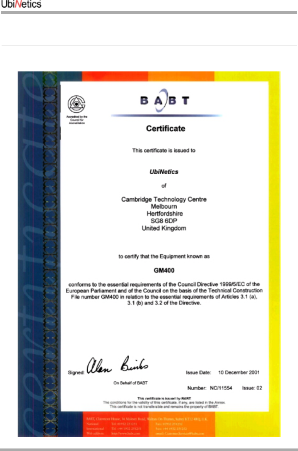
Regulatory Approval
41 of 176 GM40x GSM/GPRS Module Reference: UNDOC00048rF
6.0 Regulatory Approval

Regulatory Approval
GM40x GSM/GPRS Module Reference: UNDOC00048rF 42 of 176
UbiNetics GM40x modules have been designed to meet the most demanding Safety, Radio, Protocol,
EMC, Network and Environmental performance standards.
They are tested and approved against the following European and US standards:
UbiNetics hereby declares that GM40x modules are in compliance with the essential requirements and
other relevant provisions of Directive 1999/5/EC.
Because the modules themselves have already obtained Regulatory Approvals under the RTTE Directive,
any product that contains a UbiNetics module does not have to undergo such stringent testing as it
otherwise would.
For example, your product will not normally have to undergo Protocol or SIM testing, as Protocol and SIM
performance is already covered by module approval.
Regulatory Testing of the finished product will normally be limited to Safety, EMC and Environmental
standards (which apply to most electronic products in any case), plus Radio, SAR and Network testing.
However, the approvals already obtained by the module in these areas mean that the amount of testing of
the finished product will normally be less than would otherwise be required.
European and US Regulatory Approvals are accepted in many other countries. UbiNetics can provide an
outline of the approvals required for other world markets that have their own specific requirements, or even
help you obtain these approvals if you wish.
How UbiNetics can help
As a world leader in GSM, GPRS and UMTS technology, and with offices in the UK, Hong Kong, India and
the United States, UbiNetics Ltd. has wide experience of designing and selling compliant wireless
telecommunications products in global markets.
We are now able to offer our Interoperability Test and Approval expertise to other companies that have not
yet developed their own, or who merely wish to concentrate on what they do best.
These are some of the services we offer:
●Interoperability testing
●Regulatory approvals
●Network approvals
●Product Design Validation
●EMC and safety testing
●EMC consultancy.
Standard
Europe US
EN60950 Safety UL60950 edition 3
3GPP 51.010 Radio FCC part 24
3GPP 51.010 Protocol 3GPP 51.010
EN 301 489 EMC (Electromagnetic Compatibility) FCC part 15
GCF Network PTCRB
ETS 300 019 Environmental Customer specific

Regulatory Approval
43 of 176 GM40x GSM/GPRS Module Reference: UNDOC00048rF
Interoperability Testing
Regulation and test requirements are now struggling to keep pace with the speed of technological
development. Interoperability testing is now crucial for demonstrating that products actually work in the
varied environments presented by different network infrastructures.
With our detailed knowledge of the infrastructure of major networks, and access to their test beds, we are
in a unique position to offer an effective interoperability testing service.
Regulatory Approvals
We have compiled an extensive database on a large number of country requirements, both current and
future. We are therefore able to advise on requirements in your target markets during the design phase,
and obtain timely approvals for finished products. With this we can offer the following services:
●Product approvals under the R&TTE directive
●World-wide testing, application and management
●In-house Anite protocol testing
●RF and SIM Protocol testing
●Compiling Technical Construction Files
●EMC testing
●Safety/SAR testing.
Network approvals
UbiNetics have established close working relationships with network operators in the UK, Europe and the
United States. This enables us to obtain crucial network approvals on target networks with the minimum
delay.
Through the relationships we have built up with network operators, we have acquired a depth of
knowledge of their network infrastructure and network-specific test requirements. This has enabled us to
plan out field trial test routes to cover a comprehensive range of operating situations. All of this allows us to
offer the following services:
●Fully-automated field trials testing
●Functional testing against network operator requirements
●Drive testing.
All of these services can be performed for any market in the world.
Product Design Validation
Based at our main test laboratories in Melbourn, near Cambridge in the UK, our engineers have vast
experience in product validation. They are able to carry out a wide range of product testing in our
laboratories. Our offices in Hong Kong, India and North America co-ordinate testing for those markets.
Through our close working relationship with BABT, we have achieved partner status, so we are also able to
call upon the global resources of BABT.
We can ensure that your product meets its physical design specification in all areas, using the following
services:
●Environmental and mechanical testing
●Accelerated Life Testing (ALT)
●AT command testing
●Supplementary Services testing
●Testing the product against product specifications; this may include compatibility with different opera-
tion systems, MMI and compliance with documentation.

Regulatory Approval
GM40x GSM/GPRS Module Reference: UNDOC00048rF 44 of 176
EMC and Safety
EMC performance is crucial both for obtaining regulatory approval and for determining product
acceptability. We can advise on EMC implications during the design phase, then, with our partners in the
UK, carry out the necessary test procedures and evaluate the results. In cases where EMC performance
needs to be improved, we are able to suggest product modifications.
Other Services
Our extensive experience of selling wireless products into world markets also enables us to advise clients
on many other aspects of doing business around the world, such as
●importing / exporting requirements
●country-specific labelling requirements.
Memberships
Our memberships of the following bodies allows us to keep up to date and even ahead of the game in
world regulation and test requirements:
●GSM Association (MoU)
●ETSI
●GCF.

Definitions and Abbreviations
45 of 176 GM40x GSM/GPRS Module Reference: UNDOC00048rF
7.0 Definitions and Abbreviations
This section contains a list of common definitions and abbreviations used in this document.
7.0.1 Definitions
7.0.2 Syntactical Definitions
The following syntactical definitions are used in this document:
7.0.3 Abbreviations
The following abbreviations are used in this document:
Off-line Command State The modem enters this state after power up i.e. the modem is not in a data call (off-
line) and ready to accept AT commands.
On-line Data State The modem will change from off-line command state to on-line data state after
successfully setting up a data call. This allows the mobile station to exchange data
with the remote station.
On-line Command State To change from on-line data state to on-line command state the DTE sends the escape
sequence +++. This allows AT commands to be sent to the modem whilst still retaining
the data connection to the remote station. The command ATH will end the data call
and ATO will return to on-line data state.
Remote Station This is the term given to describe the equipment or modem at the other end of the link,
when making a mobile originated or mobile terminated call.
Mobile Station Throughout this document this term refers to the UbiNetics modem.
Mobile Originated (MO) This means a voice call, data call or SMS has initiated by the modem.
Mobile Terminated (MT) This means a voice call, data call or SMS has been received by the modem.
<cr> Carriage Return character.
<lf> Line Feed character.
<...> a sub-parameter enclosed within angle brackets, is a syntactical element. The brackets themselves
do not appear in the command line.
[...] Optional sub-parameter, is enclosed within square brackets. This indicates the element may or may
not be present within a result code or can be omitted from the command string. The square
brackets themselves do not appear in the command line.
underline Indicates a default setting of a sub-parameter value after a factory reset.
AT ATtention, used to start a command line
CBM Cell Broadcast Message
CCITT Consultative Committee on International Telegraphy and Telephony
DCE Data Connection Equipment, refers to the modem which is controlled by the computer and application
software. Also see TA

Definitions and Abbreviations
GM40x GSM/GPRS Module Reference: UNDOC00048rF 46 of 176
DTE Data Terminal Equipment, refers to the computer which is used to control the modem via the serial
interface.
EMC Electromagnetic Compatibility
ETSI European Telecommunications Standards Institute
GPRS General Packet Radio Service
GSM Global System for Mobile communications
IMEI International Mobile station Equipment Identity
ITU-T International Telecommunication Union = Telecommunication Standardisation Sector
ME Mobile Equipment; refers to the modem
MO Mobile Originated, when a call is made from the mobile station
MT Mobile Terminated, when an incoming call is answered by the mobile station
PA Power Amplifier (transmitter)
PAD Packet Assembler/Disassembler
PDU Protocol Data Unit
PIN Personal Identification Number: a 4-digit code used to protect the SIM
PPP Point-to-Point Protocol
PUK Unblocking Key. An 8-digit code used to unblock SIM PIN
RF Radio Frequency
RLP Radio Link Protocol
SAR Specific Absorption Rate
SIM Subscriber Identity Module
SMS Short Message Service
TE Terminal Equipment. Refers to the computer and application software which is controlling the modem,
via the AT command interface
TA Terminal Adapter. Within this text the TA refers to the modem which is controlled by the application
software, via the AT command interface
TAPI Telephone APplication Interface.
TCP Transmission Control Protocol
ME Mobile Equipment. Within this text the ME refers to the UbiNetics modem, which is controlled by the
application software. As seen from the AT command interface, the TA and ME have been implemented
as a single entity
TIA Telecommunications Industry Association
UDP User Datagram Protocol
VSWR Voltage Standing Wave Ratio

AT Commands: Introduction
47 of 176 GM40x GSM/GPRS Module Reference: UNDOC00048rF
8.0 AT Commands: Introduction
8.1 Overview
UbiNetics Ltd. produces a range of dual-band GSM/GPRS modules, which give compatible mobile
devices wireless connectivity using the GSM900/1800/1900 cellular networks.
The modules are controlled by industry-standard AT commands which are defined by ETSI in GSM 07.07,
GSM 07.05, V.25ter and T.32. These may be downloaded from http://www.etsi.org or http://www.3gpp.org
This manual lists the AT command set currently supported by the UbiNetics GPRS module. It is not
intended to be a full specification of each AT command, but a quick reference to the syntax which
includes any details specific to the implementation. For a full specification of each command, please see
the original ETSI and ITU documentation.
All other commands not included within this document, whether recognised or not, are not supported and
their use is not guaranteed.
8.2 Format of the AT Command String and Result Code
In general AT commands comprise three parts, which start with AT, followed by a command and ended
with the line termination character <cr>. The exceptions to this are A/ and +++, which are sent without AT
and carriage return.
The response from each command varies and is documented within the following text. In general, a
successful command will respond with OK, whilst an unrecognised command will fail with an error. If the
command is recognised but fails due to an invalid sub-parameter, equipment error or network error, a
more informative result code may be obtained by using the command AT+CMEE=2, to display extended
verbose result codes.
8.2.1 Types of Commands
AT commands have three basic structures, some of which are not applicable to all command types. For
further information, see the individual commands.
Test Commands
Test Commands (ATxxx=?) test the existence of a command and checks its range of sub-parameter(s).
UbiNetics may not support the full range of values returned by this command.
Read Commands
Read Commands (ATxxx?) read the current value of the sub-parameter(s).
Set Commands
Set Commands (ATxxx=a,b) will attempt to set a new subparameter value(s). If the command is
successful the AT command interpreter will return OK (if ATV1, ATQ0), otherwise an error or informative
result code will be returned.

AT Commands: Introduction
GM40x GSM/GPRS Module Reference: UNDOC00048rF 48 of 176
8.2.2 Command Line Editing
When using a terminal screen to talk directly to the modem, the Back Space <bs> character is useful for
deleting previous character(s) sent in error. However Back Space cannot delete the initial AT or the line
termination character <cr>.
8.2.3 Command Line Termination
The line termination character Carriage Return <cr> tells the modem to accept and process the
command.
8.2.4 Command Formatting
Result code(s) that are sent from the modem use the Line Feed character <lf> appended to a Carriage
Return <cr>, to format the text correctly on different lines.
8.2.5 Command Line Echo
In command mode, characters that are sent to the modem are echoed back to the DTE. This can be
disabled by using the AT Command ATE0.
8.2.6 Concatenation
Several commands may be joined together to form a single command string, that must be no longer than
350 characters (including the line termination character <cr>).
When concatenating commands, only one AT is required at the beginning of the string and one carriage
return at the end. In the middle, commands are joined together in the order to be processed.
Extended commands, i.e. ones which start AT+ also require an additional semi-colon (;). If an error occurs
while processing the string, the following commands will not be processed and an error returned. See the
examples below:
ATE0V1D123456;<cr>
AT+CMGR=1,2;+CMGR=3,4<cr>
Some AT commands are not suitable for concatenation and careful thought is required before stringing
together many AT commands.
8.2.7 Response Code Format
The format of the result code is controlled by ATV. The default setting is verbose <cr><lf>OK<cr><lf>.
8.2.8 Response Code Suppression
Response code suppression is controlled by ATQ. By default response codes are shown.
8.2.9 Final Result Code
This is the last result code returned by the command being processed. In the case of the Dial command
this could be OK, NO CARRIER, NO DIALTONE, NO ANSWER, BUSY, ERROR.

AT Commands: Introduction
49 of 176 GM40x GSM/GPRS Module Reference: UNDOC00048rF
8.2.10 Intermediate Result Code
This is a result code which is displayed before the final result code. In the case of the Dial command this
could be CONNECT or CONNECT<text>.
8.2.11 Unsolicited Result Code
These are result codes generated by an event not directly linked to the command which is being
processed. A good example is an incoming voice call will generate RING or +CRING: VOICE when
AT+CRC=1.

Commands Specified by GSM 07.07
GM40x GSM/GPRS Module Reference: UNDOC00048rF 50 of 176
9.0 Commands Specified by GSM 07.07
This section covers the AT commands specified within GSM 07.07 and supported by UbiNetics devices.
9.1 General Commands
9.1.1 +CGMI Request Manufacturer Identification
Description
This command causes the modem to return the manufacturer-specific identity.
Parameters
None.
9.1.2 +CGMM Request Model Identification
Description
This command causes the modem to return the manufacturer-specific model identity.
Parameters
None.
9.1.3 +CGMR Request Revision Identification
Description
This command causes the modem to return the manufacturer-specific model revision identity.
Parameters
None.
Command Possible Response
AT+CGMI=?
AT+CGMI Ubinetics Ltd.
Command Possible Response
AT+CGMM=?
AT+CGMM <model identity>
Command Possible Response
AT+CGMR=?
AT+CGMR <revision>

Commands Specified by GSM 07.07
51 of 176 GM40x GSM/GPRS Module Reference: UNDOC00048rF
9.1.4 +CGSN Request Product Serial Number Identification
Description
This command causes the modem to return the product serial number.
Parameters
None.
9.1.5 +CSCS Select DTE Character Set
Description
This command selects the character set used by the modem, to allow correct conversion of the character
strings between the DTE and the modem.
Parameters
<chset> GSM GSM alphabet
“IRA”International Reference Alphabet
HEX Hexadecimal numbers from 00 to FF
9.1.6 +CIMI Request International Mobile Subscriber Identity
Description
Execution command causes the modem to return the International Mobile Subscriber Identity Number
(IMSI), when IMSI attached to a network.
Parameters
<imsi> International Mobile Subscriber Identity number
Command Possible Response
AT+CGSN=?
AT+CGSN <serial number>
Command Possible Response
AT+CSCS=? +CSCS: (list of supported <chset>s)
AT+CSCS? +CSCS: <chset>
AT+CSCS=<chset>
Command Possible Response
AT+CIMI <imsi>

Commands Specified by GSM 07.07
GM40x GSM/GPRS Module Reference: UNDOC00048rF 52 of 176
9.1.7 +WS46 Select Wireless Network
Description
Selects the cellular network Wireless Data Service (WDS) to operate with the modem.
Parameters
<n> 12 GSM digital cellular
9.1.8 +CSTA Select type of address
Description
Selects the type of number for further dialling commands according to GSM specifications.
Parameters
<type> type of address octet in integer format
129 default
145 default when dialling string includes the international access code character ‘+’
9.2 Call Control Commands
9.2.1 D Dial Command
Description
Initiates a mobile-originated call to the destination number <n>.
Parameters
<n> destination number containing the following characters 0-9,*,#,+,A,B,C,D
<mgsm>
, pause during dialling, ignored
Command Possible Response
AT+WS46=? (list of supported <n>s)
AT+WS46? <n>
AT+WS46=[<n>]
Command Possible Response
+CSTA=? +CSTA: (list of supported <type>s)
+CSTA? +CSTA: <type>
+CSTA=[<type>]
Command Possible Response
ATD<n>[<mgsm>][;] see the table below

Commands Specified by GSM 07.07
53 of 176 GM40x GSM/GPRS Module Reference: UNDOC00048rF
T tone dialling, ignored
P pulse dialling, ignored
! register recall/hook flash, ignored
W wait for dial tone, ignored
@ wait for quiet answer, ignored
I restrict CLI presentation, overriding AT+CLIR setting
; originate a voice call
Note: ATD112; is reserved for emergency calls only.
9.2.2 D> Dial Selected Phone Book
Description
This command initiates a Mobile Originated call, from the specified phone book and location.
Parameters
<mem> EN Emergency Number
AD SIM phone book
<n> Memory location of number to dial
I Restrict CLI presentation, overriding AT+CLIR setting
; Originate a voice call
9.2.3 D> Dial Current Phone Book
Description
Initiates a mobile originated call, from the currently selected phone book, location <n>.
Verbose Result Code Numeric Result
Code Description
OK 0Command executed, no error
CONNECT 1Connection set up (ATX=0)
CONNECT <text> 1Connection set up (ATX=n) where n>0
RING 2Ringing tone is present (AT+CRC=0)
NO CARRIER 3Call failed to connect or disconnected
ERROR 4Invalid command or too long
BUSY 7The called party is currently in another call
NO ANSWER 8Connection failed up to time out
Command Possible Response
ATD><mem><n>[I][;] see the table within Dial Command
Command Possible Response
ATD><n>[I][;] see the table within Dial Command

Commands Specified by GSM 07.07
GM40x GSM/GPRS Module Reference: UNDOC00048rF 54 of 176
Parameters
<n> number of memory location to dial
I restrict CLI presentation, overriding AT+CLIR setting
; originate a voice call
9.2.4 +CHMOD Call mode
Description
Selects the call mode for dialling commands or for next answering command. The mode can be either
single or alternating (for example, voice/data, voice/fax).
Parameters
<mode> 0 single mode
1 alternating voice/fax
2 alternating voice/data
3 voice followed by data
9.2.5 +CHUP Hangup Call
Description
Execution command hangs up all active calls, giving an assured procedure to terminate an alternating
mode call.
Parameters
None.
9.2.6 +CBST Select Bearer Service Type
Description
Set command selects the bearer service for Mobile Originated calls. Values may also be used during
mobile terminated data call setup.
Command Possible Response
+CMOD=? +CMOD: (list of supported <mode>s)
+CMOD? +CMOD: <mode>
+CMOD=[<mode>]
Command Possible Response
AT+CHUP

Commands Specified by GSM 07.07
55 of 176 GM40x GSM/GPRS Module Reference: UNDOC00048rF
Parameters
<speed> 7 9600 bps (V.32)
12 9600 bps (V.34)
14 14400 bps (V.34)
71 9600 bps (V.110)
75 14400 bps (V.110)
<name> 0 data circuit asynchronous (UDI or 3.1 kHz modem)
<ce> Sets whether error correction is performed by RLP, or by other means
0 transparent
1 non-transparent
9.2.7 +CRLP Radio Link Protocol
Description
Radio link protocol (RLP) parameters used for non-transparent data calls.
Parameters
<iws> 0-61 IWF to MS window size
<mws> 0-61 MS to IWF window size
<t1> 39-48-255 acknowledgement timer t1, in 10ms units
<n2> 1-100-255 retransmission attempts n2 (the default subject to change)
Notes
●Only version 1 is supported.
●<ver> and <t4> are not implemented.
●Not all of the combinations of parameters have not been tested.
Command Possible Response
AT+CBST=? +CBST: (list of supported <speed>s),(list of supported
<name>s),(list of supported <ce>s)
AT+CBST? +CBST: <speed>,<name>,<ce>
AT+CBST=[<speed>[,<name>[,<ce>]]]
Command Possible Response
AT+CRLP=? +CRLP: (list of supported <iws>s),(list of supported <mws>s),(list of
supported <t1>s),(list of supported <n2>s)]<cr><lf>
[+CRLP: (list of supported <iws>s),(list of supported <mws>s),(list of
supported <t1>s),(list of supported <n2>s)][...]]
AT+CRLP? +CRLP: <iws>,<mws>,<t1>,<n2>][<cr><lf>
+CRLP:<iws>,<mws>,<t1>,<n2>][...]]
AT+CRLP=[<iws>[,<mws>[,<t1>[,<n2
>]]]]

Commands Specified by GSM 07.07
GM40x GSM/GPRS Module Reference: UNDOC00048rF 56 of 176
9.2.8 +CR Service Reporting Control
Description
Set command controls whether or not intermediate result code is returned from the modem to the DTE. If
enabled, the intermediate result code is transmitted when the modem has established the speed, which is
before the final result code connect.
Parameters
<mode> 0 disables reporting
1 enables reporting
<serv> service supported, displayed after connect message
ASYNC asynchronous transparent
REL ASYNC asynchronous non-transparent
9.2.9 +CEER Extended Error Report
Description
This command returns information text, which offers the user an extended report for the reason of the
failure of the last unsuccessful call set up (originating or answering) or in-call modification.
Parameters
<report> no error
unassigned number
no route to destination
channel unacceptable
operator determined barring
normal call clearing
user busy
no user responding
user alerting no answer
call rejected
number changed
Command Possible Response
AT+CR=? +CR: (list of supported <mode>s)
AT+CR? +CR: <mode>
AT+CR=[<mode>]
intermediate result code +CR: <serv>
Command Possible Response
AT+CEER +CEER: <report>

Commands Specified by GSM 07.07
57 of 176 GM40x GSM/GPRS Module Reference: UNDOC00048rF
non selected user clearing
destination out of order
invalid number format
facility rejected
response to status enquiry
normal unspecified
no channel available
network out of order
temporary failure
switching equipment congestion
access information discarded
requested channel unavailable
resources unavailable
quality of service unavailable
requested facility unsubscribed
incoming calls barred within CUG
bearer capability not authorized
bearer capability not available
service not available
bearer service not implemented
ACM reached ACM maximum
facility not implemented
only restricted bearer cap. avail.
service not implemented
invalid TI
no member of CUG
incompatible destination
invalid transit network selection
incorrect message
invalid mandatory information
message type not implemented
message type incompatible
info element not implemented
conditional info element error
message incompatible
recovery on time expiry

Commands Specified by GSM 07.07
GM40x GSM/GPRS Module Reference: UNDOC00048rF 58 of 176
protocol error
interworking error
bearer service not available
no TI available
timer 303 expiry
establishment failure
no error
operation failed
timeout
bearer service not compatible
9.2.10 +CRC Cellular Result Codes
Description
Set command controls the use of extended format reporting during a MT call set up.
Parameters
<mode> 0 disables extended format (i.e. +RING)
1 enables extended format (i.e. +CRING: VOICE)
<type> ASYNC asynchronous transparent
REL ASYNC asynchronous non-transparent
VOICE normal voice
FAX Facsimile
9.2.11 +CRING Result code
Description
Result code only generated when AT+CRC=1. See See “+CRC Cellular Result Codes” on page 58.
Command Possible Response
AT+CRC=? +CRC: (list of supported <mode>s)
AT+CRC? +CRC: <mode>
AT+CRC=[<mode>]
unsolicited result code +CRING: <type>

Commands Specified by GSM 07.07
59 of 176 GM40x GSM/GPRS Module Reference: UNDOC00048rF
9.3 Network Service Related Commands
9.3.1 +CSNS Single Numbering Scheme
Description
Selects the bearer or teleservice to be used when a single numbering scheme call is established.
Parameters
<mode> 0 voice
1 alternating voice/fax; fax first (TS61)
2 fax (TS 62)
3 alternating voice/data, voice first (BS61)
4data
5 alternating voice/fax, fax first (TS61)
6 alternating voice/data, data first (BS61)
7 voice followed by data (BS81)
9.3.2 +CNUM Subscriber Number
Description
Action command returns the MSISDNs related to the subscriber. If subscriber has different MSISDN for
different services, each MSISDN is returned in a separate line.
Parameters
<alphax> optional alphanumeric string associated with <numberx>
<numberx> string type phone number of format specified by <typex>
<typex> type of address octet in integer format
<speed> as defined in AT+CBST
<service> service related to the phone number
0 asynchronous modem
Command Possible Response
AT+CSNS=? +CSNS: (list of supported <mode>s)
AT+CSNS? +CSNS: <mode>
AT+CSNS=[<mode>]
Command Possible Response
AT+CNUM=?
AT+CNUM +CNUM: [<alpha1>],<number1>,<type1>
[,<speed>,<service>[,<itc>]][<cr><lf>
+CNUM: [<alpha2>],<number2>,<type2>
[,<speed>,<service>[,<itc>]][...]]

Commands Specified by GSM 07.07
GM40x GSM/GPRS Module Reference: UNDOC00048rF 60 of 176
1 synchronous modem
2 PAD access (asynchronous)
3 packet access (synchronous)
4 voice
5 fax
<itc> information transfer capability
0 3.1 kHz
1 UDI
9.3.3 +CREG Network Registration
Description
Displays network registration status.
Parameters
<n> 0 disable network registration unsolicited result code
1 enable network registration unsolicited result code
<stat> 0 not registered new operator to registered and not searching
1 registered, home network
2 not registered, currently searching a new operator to register with
3 registration denied
4 unknown
5 registered, roaming
Command Possible Response
AT+CREG=? +CREG: (list of supported <n>s)
AT+CREG? +CREG: <n>,<stat>
AT+CREG=[<n>]
unsolicited result code +CREG: <stat>

Commands Specified by GSM 07.07
61 of 176 GM40x GSM/GPRS Module Reference: UNDOC00048rF
9.3.4 +COPS Operator Selection
Description
Registers/displays network operators available.
Parameters
<stat> availability of operator
0 unknown
1 available
2 current
3 forbidden
<oper> shows the operator identity, within speech marks, in the format set by <format>
<mode> registration mode
0 automatic (<oper> field is ignored)
1 manual (<oper> field shall be present)
2 de-register from network
3 set only <format> (for read command AT+COPS?). Do not attempt registration /
de-registration (<oper> field is ignored); this value is not applicable in read
command response
4 manual/automatic (<oper> field shall be present); if manual selection fails,
automatic mode <mode>=0) is entered
<format> format of <oper> reports
0 long format alphanumeric <oper>
1 short format alphanumeric <oper>
2 numeric <oper>
Command Possible Response
AT+COPS=? +COPS: ([list of supported <stat>,long alphanumeric
<oper>,short alphanumeric <oper>,numeric
<oper>)s][,,(list of supported <mode>s),(list of
supported <format>s)]
AT+COPS? +COPS: <mode>[,<format>,<oper>]
AT+COPS=[<mode>[,<format>[,<oper>]]]
e.g.
AT+COPS=1,2,"23410"

Commands Specified by GSM 07.07
GM40x GSM/GPRS Module Reference: UNDOC00048rF 62 of 176
9.3.5 +CLCK Facility Lock
Description
This command is used to lock, unlock or interrogate the modem or a network facility. A password is
required for some actions.
Parameters
<fac> (within speech marks)
SC SIM (lock SIM card) SIM asks password in modem power-up and
when this lock command issued
AO BAOC (Bar All Outgoing Calls)
OI BOIC (Bar Outgoing International Calls)
OX BOIC-exHC (Bar Outgoing International Calls except to Home Country)
AI BAIC (Bar All Incoming Calls)
IR BIC-Roam (Bar Incoming Calls when Roaming outside the home country)
AB All Barring services
AG All outGoing barring services
AC All inComing barring services
FD SIM fixed dialling memory feature, if PIN2 authentication has not been
done during the current session, PIN2 is required as <passwd>
<mode> 0 unlock
1 lock
2 query status
<status> 0 not active (when mode=2, indicates no services are active)
1 active
<passwd> the same password used by AT+CPWD, within speech marks
<classx> a sum of integers each representing a class of information
1 voice (telephony)
2 data (refers to all bearer services; with <mode>=2 this may refer only to
some bearer service if TA does not support values 16, 32, 64 and 128)
4 fax (facsimile services)
7 all classes
Command Possible Response
AT+CLCK=? +CLCK: (list of supported <fac>s)
AT+CLCK=<fac>,<mode>[,<passwd>],<class>]]
e.g.
AT+CLCK="SC",0,"1111"
when <mode>=2 and command successful;
+CLCK: <status>[,<class1>[<cr><lf>
+CLCK: <status>,<class2>[...]]
Commands Specified by GSM 07.07
63 of 176 GM40x GSM/GPRS Module Reference: UNDOC00048rF
9.3.6 +CPWD Change Password
Description
Action command sets a new password for the facility lock function defined by command facility lock
(AT+CLCK).
Parameters
<fac> (within speech marks)
SC lock SIM card, asks password in modem power-up and when this loc
command issued (SIM PIN1)
AO bar All Outgoing Calls (BAOC)
OI bar Outgoing International Calls (BOIC)
OX bar Outgoing International Calls except to Home Country (BOIC-exHC)
AI bar All Incoming Calls (BAIC)
IR bar Incoming Calls when Roaming outside the home country (BIC-Roam)
AB all Barring services
AG all outGoing barring services
AC all inComing barring services
P2 SIM PIN2
<pwdlength> integer type, maximum length of the password for the facility (see AT+CPWD=?)
<oldpwd> string type; shall be the same as password specified for the facility from the modem AT
command interface or with command Change Password AT+CPWD
<newpwd> string type; shall be the new password for the facility from the modem AT command
interface or with command Change Password AT+CPWD
9.3.7 +CLIP Calling Line Identification Presentation
Description
This command allows the called subscriber to get the Calling Line Identity (CLI) of the calling party, in a
mobile terminated call.
Command Possible Response
AT+CPWD=? +CPWD: list of supported (<fac>,<pwdlength>)s
AT+CPWD=<fac>,<oldpwd>,<newpwd>
e.g.
AT+CPWD=”SC”,”1234”,”4321”
Command Possible Response
AT+CLIP=? +CLIP: (list of supported <n>s)
AT+CLIP? +CLIP: <n>,<m>
AT+CLIP=[<n>]
unsolicited result code, displayed when CLI is enabled
for the first two rings +CLIP: <number>,<type>

Commands Specified by GSM 07.07
GM40x GSM/GPRS Module Reference: UNDOC00048rF 64 of 176
Parameters
<n> sets/shows the result code presentation status in the modem
0 disable
1 enable
<m> 0 CLIP not provisioned (parameter shows the subscriber CLIP service status in the net
work)
1 CLIP provisioned
2 unknown (e.g. no network, etc.)
<number> String type phone number in "quotes", in the format specified by <type>
<type> type of number
129 dial string without the international access character
145 dial string which includes the international access character "+"
9.3.8 +CLIR Calling Line Identification Restriction
Description
This command enables/disables CLI to the called party, when originating a call.
Parameters
<n> sets CLI status for following calls.
0 presentation indicator is used according to the subscription of the CLIR service.
1 CLIR invocation (hide)
2 CLIR suppression (show)
<m> Shows the subscriber CLIR service status in the network
0 CLIR not provisioned
1 CLIR provisioned in permanent mode
2 unknown (e.g. no network, etc.)
3 CLIR temporary mode presentation restricted
4 CLIR temporary mode presentation allowed
Command Possible Response
AT+CLIR=? +CLIR: (list of supported <n>s)
AT+CLIR? +CLIR: <n>,<m>
AT+CLIR=[<n>]

Commands Specified by GSM 07.07
65 of 176 GM40x GSM/GPRS Module Reference: UNDOC00048rF
9.3.9 +COLP Connected Line Identification Presentation
Description
COLP enables a calling subscriber to get the connected line identity (COL) of the called party after setting
up a mobile originated call.
Parameters
<n> Sets/shows the result code presentation status in the TA
0 disable
1 enable
<m> Shows the subscriber COLP service status in the network
0 COLP not provisioned
1 COLP provisioned
2 unknown (e.g. no network, etc.)
<number> String type phone number in "brackets" of format specified by <type>
<type> Type of address octet in integer format. 145 when the dial string contains +, otherwise 129.
9.3.10 +CCUG Closed User Group
Description
Allows control of the Closed User Group supplementary service.
Parameters
<n> 0 disable CUG temporary mode
1 enable CUG temporary mode
<index> 0...9 CUG index
10 no index
<info> 0 no information
1 suppress OA
2 suppress preferential CUG
Command Possible Response
AT+COLP=? +COLP: (list of supported <n>s)
AT+COLP? +COLP: <n>,<m>
AT+COLP=[<n>]
Intermediate result code +COLP:<number>,<type>[,<subaddr>,<satype>
[,<alpha>]]
Command Possible Response
AT+CCUG=?
AT+CCUG? +CCUG: <n>,<index>,<info>
AT+CCUG=[<n>[,<index>[,<info>]]]

Commands Specified by GSM 07.07
GM40x GSM/GPRS Module Reference: UNDOC00048rF 66 of 176
3 suppress OA and preferential CUG
9.3.11 +CCFC Call Forwarding Number and Conditions
Description
This command allows control over the call forwarding supplementary service providing, registration,
erasure, activation, deactivation and status query.
Parameters
<reason> 0 unconditional
1 mobile busy
2 no reply
3 not reachable
4 all call forwarding
5 all conditional call forwarding
<mode> 0 disable
1 enable
2 query status
3 registration
4 erasure
<number> String type phone number of forwarding address in format specified by <type>
<type> Type of number
129 dial string without the international access character
145 dial string which includes the international access character "+"
<subaddr> String type sub-address of format specified by <satype>
<satype> Type of sub-address octet in integer format
128 default
<class> a sum of integers each representing a class of information
1 voice (telephony)
2 data (refers to all bearer services; with <mode>=2 this may refer only to some
bearer service if TA does not support values 16, 32, 64 and 128)
Command Possible Response
AT+CCFC=? +CCFC: (list of supported <reason>s)
AT+CCFC=<reason>,<mode>[,<number>[,<type>[,<c
lass>[,<subaddr>[,<satype>[,<time>]]]]]]
e.g.
AT+CCFC=0,3,"01763262222"
When <mode>=2 and command successful;
+CCFC: <status>,<class1>[,<number>,
<type>[,<subaddr>,<satype>[,<time>]]][<cr><lf>
+CCFC: <status>,<class2>[,<number>,
<type>[,<subaddr>,<satype>[,<time>]]][...]]

Commands Specified by GSM 07.07
67 of 176 GM40x GSM/GPRS Module Reference: UNDOC00048rF
4 fax (facsimile services)
7 All classes
8 short message service
16 data circuit sync
32 data circuit async
64 dedicated packet access
128 dedicated PAD access
<time> 1-20-30 when "no reply" is enabled or queried, this gives the time in seconds to wait
before call is forwarded
<status> 0 not active (when <mode>=2, means not active for all class)
1 active
9.3.12 +CCWA Call Waiting
Description
This command allows control over the call waiting supplementary service providing activation,
deactivation, and status query.
Parameters
<n> sets/shows the result code presentation status in the modem
0 disable
1 enable
<mode> when <mode> parameter is not given, network is not interrogated
0 disable
1 enable
2 query status
<class> a sum of integers each representing a class of information
1 voice (telephony)
2 data (refers to all bearer services; with <mode>=2 this may refer only to some
bearer service if TA does not support values 16, 32, 64 and 128)
4 fax
8 short message service
Command Possible Response
AT+CCWA=? +CCWA: (list of supported <n>s)
AT+CCWA? +CCWA: <n>
AT+CCWA=[<n>[,<mode>[,<class>]]] When <mode>=2 and command successful;
+CCWA: <status>,<class1>[<cr><lf>
+CCWA: <status>,<class2>[...]]
unsolicited result code (when <n>=1) +CCWA: <number>,<type>,<class>[,<alpha>]

Commands Specified by GSM 07.07
GM40x GSM/GPRS Module Reference: UNDOC00048rF 68 of 176
16 data circuit sync
32 data circuit async
64 dedicated packet access
128 dedicated PAD access.
<status>
0 not active, (when <mode>=2, means not active for all class)
1 active
<number> string type phone number of calling address in format specified by <type>
<type> type of address octet in integer format
<alpha> optional string type alphanumeric representation of <number> corresponding to the entry
found in phonebook)
9.3.13 +CHLD Call Related Supplementary Services
Description
This command allows call control using Call Hold and MultiParty.
Parameters
<n> integer type
0 releases all held calls or sets User Determined User Busy (UDUB) for a waiting call
1 releases all active calls (if any exist) and accepts the other (held or waiting) call
1x releases a specific active call X
2 places all active calls (if any exist) on hold and accepts the other (held or waiting) call
2x places all active calls on hold except call X with which communication shall be
supported
3 adds a held call to the conversation
4 connects the two calls and disconnects the subscriber from both calls (ECT)
9.3.14 +CUSD Unstructured Supplementary Service Data
Description
This command allows control of the Unstructured Supplementary Service Data, for both network and
mobile initiated operations.
Command Possible Response
AT+CHLD=? +CHLD: (list of supported <n>s)
AT+CHLD=[<n>]
Command Possible Response
AT+CUSD=? +CUSD: (list of supported <n>s)

Commands Specified by GSM 07.07
69 of 176 GM40x GSM/GPRS Module Reference: UNDOC00048rF
Parameters
<n> 0 disable the result code presentation in the TA
1 enable the result code presentation in the TA
<str> string type USSD-string; when <str> parameter is not given, network is not interrogated
<dcs> Cell Broadcast Data Coding Scheme in integer format
<m> 0 no further user action required (network initiated USSD-Notify, or no further
information needed after mobile initiated operation)
1 further user action required (network initiated USSD-Request, or further
information needed after mobile initiated operation)
2 USSD terminated by network
3 other local client has responded
4 operation not supported
5 network time out Implementation
9.3.15 +CAOC Advice of charge
Description
Advice of Charge supplementary service, enabling users to obtain information on the cost of calls.
Parameters
<mode> 0 Query CCM value
1 Deactivate the unsolicited reporting of CCM value
2 Activate the unsolicited reporting of CCM value
9.3.16 +CSSN Supplementary Service Notifications
Description
Supplementary service: enables/disables network-initiated notifications.
AT+CUSD? +CUSD: <n>
AT+CUSD=[<n>[,<str>[,<dcs>]]]
unsolicited result code +CUSD: <m>[,<str>,<dcs>]
Command Possible Response
AT+CAOC=? [+CAOC: (list of supported <mode>s]
AT+CAOC? +CAOC: <mode>
AT+CAOC[=<mode>] [+CAOC: <ccm>]
Command Possible response

Commands Specified by GSM 07.07
GM40x GSM/GPRS Module Reference: UNDOC00048rF 70 of 176
Parameters
<n> CSSI result code notification
0 disable
1 enable
<m> CSSU result code notification
0 disable
1 enable
<code1> (manufacturer specific)
0 unconditional call forwarding is active
1 some of the conditional call forwardings are active
2 call has been forwarded
3 call is waiting
4 CUG call (also <index> present)
5 outgoing calls barred
6 incoming calls barred
7 CLIR suppression rejected
8 call deflected
<index> refer "Closed user group +CCUG"
<code2> (manufacturer specific)
0 forwarded call (MT call setup)
1 CUG call (also <index> present) (MT call setup)
2 call put on hold (during a voice call)
3 call retrieved (during a voice call)
4 multiparty call entered (during a voice call)
5 call on hold has been released (not a SS notification) (during a voice call)
6 forward check SS message received (can be received whenever)
7 call is being connected (alerting) with the remote party in alerting state in
explicit call transfer operation (during a voice call)
8 call has been connected with the other remote party in explicit call transfer
operation (also number and subaddress parameters may be present) (during a
voice call or MT call setup)
9 deflected call (MT call setup)
<number> string type phone number of format specified by <type>
<type> type of address octet in integer format
AT+CSSN=[<n>[,<m>]]
AT+CSSN? +CSSN: <n>,<m>
AT+CSSN=? +CSSN: (list of supported <n>s),(list of supported <m>s)

Commands Specified by GSM 07.07
71 of 176 GM40x GSM/GPRS Module Reference: UNDOC00048rF
<subaddr> string type sub-address of format specified by <satype>
<satype> type of sub-address octet in integer format
9.3.17 +CLCC List Current Calls
Description
This returns a list of current call of the modem, if any.
Parameters
<idx> call identification number; this number can be used in AT+CHLD command operations
<dir> 0 mobile originated (MO) call
1 mobile terminated (MT) call
<stat> state of the call
0 active
1 held
2 dialling (MO call)
3 alerting (MO call)
4 incoming (MT call)
5 waiting (MT call)
<mode> bearer/teleservice
0 voice
1 data
9 unknown
<mpty> 0 call is not one of multiparty (conference) call parties
1 call is one of multiparty (conference) call parties
<number> phone number in format specified by <type>, within "quotes"
<type> type of number
129 dial string without the international access character
145 dial string which includes the international access character "+"
<alpha> alphanumeric representation of <number> corresponding to the entry found in phonebook
Command Possible Response
AT+CLCC [+CLCC: <id1>,<dir>,<stat>,<mode>,
<mpty>[,<number>,<type>[,<alpha>]][<cr><lf>
+CLCC: <id2>,<dir>,<stat>,<mode>,
<mpty>[,<number>,<type>[,<alpha>]][...]]]

Commands Specified by GSM 07.07
GM40x GSM/GPRS Module Reference: UNDOC00048rF 72 of 176
9.3.18 +CPOL Preferred Operator List
Description
This command is used to edit the SIM preferred list of networks.
Parameters
<index>,<index> integer type; the order number of operator in the SIM preferred operator list. With
the execute command, if <index> is left out, the next free location shall be used
<format> If only the <format> is given, the result format changes for the read command
0 long format alphanumeric <oper>
1 short format alphanumeric <oper>
2 numeric <oper>
<oper>,<oper> string type; <format> indicates the format of <oper>; also see AT+COPS
Note: To delete an entry, give <index> but leave out <oper>.
9.3.19 +COPN Read Operator Names
Description
This command returns the list of operator names from the modem.
Parameters
<numericn> string type; operator in numeric format (see AT+COPS)
<alphan> string type; operator in long alphanumeric format (see AT+COPS)
Command Possible Response
AT+CPOL=? +CPOL: (list of supported <index>s),(list of supported
<format>s)
AT+CPOL? +CPOL: <index1>,<format>,<oper1>[<cr><lf>
+CPOL: <index2>,<format>,<oper2>[...]]
AT+CPOL=[<index>][,<format>[,<oper>]]
Command Possible Response
AT+COPN=?
AT+COPN +COPN: <numeric1>,<alpha1>[<cr><lf>
+COPN: <numeric2>,<alpha2>[...]]

Commands Specified by GSM 07.07
73 of 176 GM40x GSM/GPRS Module Reference: UNDOC00048rF
9.3.20 +CPAS Phone Activity Status
Description
Returns the phone activity status.
Parameters
<pas>0 ready allows commands
1 unavailable does not allow commands
2 unknown not guaranteed to respond to commands
3 ringing ringer is active
4 call in progress call is in progress
5 asleep low functionality state
9.4 Mobile Equipment Control and Status Commands
9.4.1 +CFUN Set Phone Functionality
Description
This command sets the level of functionality provided by the modem.
Parameters
<fun> 0 sets minimum functionality. In this mode the modem de-registers from the
network and powers down the SIM interface and RF circuitry
1 sets full functionality
Note: An ERROR returned after entering AT+CFUN=1 usually means the SIM card cannot be read. This
can be for several reasons—incorrect insertion, a damaged SIM, or a type of SIM not supported by the
module.
Command Possible response
AT+CPAS +CPAS: <pas>
AT+CPAS=? +CPAS: (list of supported <pas>s)
Command Possible Response
AT+CFUN=? CFUN: (list of supported <fun>s)
AT+CFUN? CFUN: <fun>
AT+CFUN=[<fun>]

Commands Specified by GSM 07.07
GM40x GSM/GPRS Module Reference: UNDOC00048rF 74 of 176
9.4.2 +CPIN Enter PIN
Description
This command is used to query and enter a password which is necessary before the modem will operate.
If the PIN is to be entered twice, the modem shall automatically repeat the PIN.
Parameters
<pin>,<newpin> string type values within "quotes"
<code> READY no passwords required
SIM PIN waiting for SIM PIN i.e. on power up SIM PIN 1
SIM PUK waiting for SIM PUK, SIM PIN 1 unblocking code. parameter <newpin> in
the new SIM PIN code.
PH-SIM PIN waiting for phone-to-SIM card password
PH-FSIM PIN waiting for phone-to-very first SIM card password
PH-FSIM PUK waiting for phone-to-very first SIM card un-blocking password
SIM PIN2 waiting for SIM PIN2 password. This <code> is recommended to be
returned only when the last executed command resulted in PIN2
authentication failure (i.e. +CME ERROR: 17)
SIM PUK2 waiting for SIM PUK2 password. This <code> is recommended to be
returned only when the last executed command resulted in PUK2
authentication failure (i.e. +CME ERROR: 18)
9.4.3 +CPBS Select Phone Book Memory Storage
This command selects phonebook memory storage <storage>, which is used by other phonebook
commands.
Parameters
<storage> EN Emergency Number
Command Possible Response
AT+CPIN=?
AT+CPIN? +CPIN: <code>
AT+CPIN=<pin>[,<newpin>]
e.g.
AT+CPIN?
+CPIN: SIM PIN
AT+CPIN="1234"
Command Possible Response
AT+CPBS=? +CPBS: (list of supported <storage>s)
AT+CPBS? +CPBS: <storage>[,<used>,<total>]
AT+CPBS=<storage>
e.g.
AT+CPBS="AD"

Commands Specified by GSM 07.07
75 of 176 GM40x GSM/GPRS Module Reference: UNDOC00048rF
AD SIM phone book
FD SIM fixdialling-phonebook
LD SIM last-dialling-phonebook
BD Barred dialling
LR Last-received numbers
SD SIM service numbers
LM Last missed
AF SIM fixed
<used> The number of used locations in selected memory
<total> The total number of locations in selected memory
9.4.4 +CPBR Read Phone Book Entries
Description
This command returns the phonebook entry for location <index> of the currently selected phone book
(AT+CPBS). If all queried locations are empty (but available), no information text lines may be returned.
Parameters
<index1>,<index2>,<index> range of location numbers of phonebook memory
<number> phone number in format <type>
<type> type of phone number
129 dial string without international access character
145 dial string which includes the international access character "+"
<text> text field of maximum length <tlength>
<nlength> value indicating the maximum length of field <number>
<tlength> value indicating the maximum length of field <text>
Command Possible Response
AT+CPBR=? +CPBR: (list of supported
<index>s),[<nlength>],[<tlength>]
AT+CPBR=<index1>[,<index2>] [+CPBR: <index1>,<number>,<type>
,<text>[[...]<cr><lf>
+CPBR: <index2>,<number>,<type>,<text>]]

Commands Specified by GSM 07.07
GM40x GSM/GPRS Module Reference: UNDOC00048rF 76 of 176
9.4.5 +CPBF Find Phone Book Entries
Description
This command returns phonebook entries from the current phone book which alphanumeric field start
with string <findtext>.
Parameters
<index1>,<index2> values in the range of location numbers of phonebook memory
<number> phone number of format <type>
<type> type of phone number
129 dial string without the international access character
145 dial string which includes the international access character "+"
<findtext>,<text> field of maximum length <tlength
<nlength> value indicating the maximum length of field <number>
<tlength> value indicating the maximum length of field <text>)
9.4.6 +CPBW Write Phone Book Entry
Description
This command writes an entry to location number <index> in the current phonebook.
Parameters
<index> range of valid location numbers for the selected phonebook memory. If this is omitted when
writing an entry the first free location shall be used
<number> phone number of format <type>
<type> type of phone number
129 dial string without the international access character
145 dial string which includes the international access character "+"
<text> field of maximum length <tlength>
Command Possible Response
AT+CPBF=? +CPBF: [<nlength>],[<tlength>]
AT+CPBF=<findtext>
e.g.
AT+CPBF="UbiNetics"
[+CPBF: <index1>,<number>,<type>
,<text>[[...]<cr><lf>
+CBPF: <index2>,<number>,<type> ,<text>]]
Command Possible Response
AT+CPBW=? +CPBW: (list of supported <index>s),[<nlength>],(list
of supported <type>s),[<tlength>]
AT+CPBW=[<index>][,<number>[,<type>[,<text>]]]
e.g:
AT+CPBW=1,”+441763262222”,145,”UbiNetics”
Commands Specified by GSM 07.07
77 of 176 GM40x GSM/GPRS Module Reference: UNDOC00048rF
<nlength> value indicating the maximum length of field <number>
<tlength> value indicating the maximum length of field <text>
Note: To delete an entry, only specify the <index> field.
9.4.7 +CRSL Ringer Sound Level
Description
This command is queries and sets, the sound level of the incoming call ringer.
Parameters
<level> integer type value
0-175-255 smallest value represents the lowest sound level
9.4.8 +CRSM Restricted SIM access
Description
Transmits SIM commands to mobile equipment. Can be used in place of +CSIM for easier but more limited
access to the SIM database.
Parameters
<command> 176 READ BINARY
178 READ RECORD
192 GET RESPONSE
214 UPDATE BINARY
220 UPDATE RECORD
242 STATUS
All other values are reserved
NOTE: The ME internally executes all commands necessary for selecting the desired
file, before performing the actual command.
<fileid> Integer type: the identifier of a elementary datafile on SIM. Mandatory for every
command except STATUS
<P1>, <P2>, <P3>Integer type; parameters passed on by the ME to the SIM. These parameters are
mandatory for every command, except GET RESPONSE and STATUS.
Command Possible Response
AT+CRSL=? +CRSL: (list of supported <level>s)
AT+CRSL? +CRSL: <level>
AT+CRSL=<level>
Command Possible response
AT+CRSM=?
AT+CRSM=<command>[,<fileid>[,<P1>,<P2>,<P3>[,<data>]]] +CRSM: <sw1>,<sw2>[,<response>]

Commands Specified by GSM 07.07
GM40x GSM/GPRS Module Reference: UNDOC00048rF 78 of 176
<data> Information written to the SIM (hexadecimal character format; refer +CSCS)
<sw1>, <sw2> Integer type; information from the SIM about the execution of the actual command.
These parameters are sent to the terminal on successful or failed execution of the
command
<response> Response of a successful completion of the command issued (hexadecimal
character format: see +CSCS). STATUS and GET RESPONSE return data, which gives
information about the current elementary datafield. This information includes the type
of file and its size. In response to the READ BINARY or READ RECORD commands the
requested data is returned. <response> is not returned after a successful UPDATE
BINARY or UPDATE RECORD command
9.4.9 +CLVL Set Speaker Amplifier Gain
Description
This command is used to select the output level of the loudspeaker output.
Parameters
<level> integer type value
0-175-255 smallest value represents the lowest sound level
9.4.10 +CMUT Mute Control
Description
Enable or disables voice muting.
Parameters
<n>0 muteoff
1 muteon
Command Possible Response
AT+CLVL=? +CLVL: (list of supported <level>s)
AT+CLVL? +CLVL: <level>
AT+CLVL=<level>
Command Possible response
AT+CMUT=? +CMUT: (list of supported <n>s)
AT+CMUT? +CMUT: <n>
AT+CMUT=<n>

Commands Specified by GSM 07.07
79 of 176 GM40x GSM/GPRS Module Reference: UNDOC00048rF
9.4.11 +CACM Accumulated Call Meter
Description
Allows the call meter to be read and reset.
Parameters
<passwd> string SIM PIN2
<acm> string accumulated call meter value (see also <ccm> in +CAOC)
9.4.12 +CAMM Accumulated Call Meter Maximum
Description
Allows call meter maximum to be set and values to be read.
Parameters
<acmmax> string accumulated call meter maximum value (see also <ccm> in AT+CAOC)
0 disables ACMmax
<passwd> string SIM PIN2
9.4.13 +CPUC Price Per Unit and Currency Table
Description
Sets the price per unit and currency table to allow conversion between home units and other currency
units.
Parameters
<currency> string three-character currency code (e.g. "GBP", "DEM") as specified by AT+CSCS
<ppu> string price per unit; dot is used as a decimal separator (e.g. "3.34")
Command Possible response
AT+CACM=?
AT+CACM? +CACM: <acm>
AT+CACM=[<passwd>]
Command Possible response
AT+CAMM? +CAMM: <acmmax>
AT+CAMM=?
AT+CAMM=[<acmmax>[,<passwd>]]
Command Possible response
AT+CPUC=?
AT+CPUC? +CPUC: <currency>,<ppu>
AT+CPUC=<currency>,<ppu>[,<passwd>]

Commands Specified by GSM 07.07
GM40x GSM/GPRS Module Reference: UNDOC00048rF 80 of 176
<passwd> string SIM PIN2
9.4.14 +CCWE Call Meter Maximum Event
Description
Determines whether the result code +CCWV (which warns when less than 30 seconds call time remains
short of the maximum) is sent.
Parameters
<mode>0 Disable the call meter warning event
1 Enable the call meter warning event
9.4.15 +CLAC List All Available AT Commands
Description
Returns the AT commands available to the user.
Parameters
<AT Command > Defines the AT command, including the prefix AT.
9.5 Mobile Equipment Errors
9.5.1 +CMEE Mobile Equipment Errors
Description
This command controls the presentation of result codes, generated by errors relating the functionality of
the modem.
Command Possible response
AT+CCWE=? +CCWE: (list of supported<mode>s)
AT+CCWE? +CCWE: <mode>
AT+CCWE=<mode>
Command Possible response
AT+CLAC <AT Command1> [<CR> <LF> <ATCommand2>[…]]
AT+CLAC=?
Command Possible Response
AT+CMEE =? +CMEE: (list of supported <n>s)

Commands Specified by GSM 07.07
81 of 176 GM40x GSM/GPRS Module Reference: UNDOC00048rF
Parameters
<n> 0 disable result code and use ERROR instead
1 enable result code and use numeric <err> values
2 enable result code and use verbose <err> values
<err> for a complete list of error codes, see CME result codes.
9.5.2 +CME ERROR Mobile Equipment Error Result Code
Description
Similar in operation to the normal ERROR result code. None of the following commands in the same
command line is executed.
Parameters
<err> Numeric format Verbose format
0 Phone failure
1 No connection to phone
2 Phone-adaptor link reserved
3 Operation not allowed
4 Operation not supported
5 PH-SIM PIN required
6 PH-FSIM PIN required
7 PH-SIM PUK required
10 SIM not inserted
11 SIM PIN required
12 SIM PUK required
13 SIM failure
14 SIM busy
15 SIM wrong
16 incorrect password
17 SIM PIN2 required
18 SIM PUK2 required
20 memory full
21 invalid index
22 not found
23 memory failure
AT+CMEE? +CMEE: <n>
AT+CMEE=[<n>]
result code +CME ERROR: <err>

Commands Specified by GSM 07.07
GM40x GSM/GPRS Module Reference: UNDOC00048rF 82 of 176
24 text string too long
25 invalid characters in text string
26 dial string too long
27 invalid characters in dial string
30 no network service
31 network timeout
32 network not allowed - emergency calls only
40 network personalisation PIN required
41 network personalisation PUK required
42 network subset personalisation PIN required
43 network subset personalisation PUK required
44 service provider personalisation PIN required
45 service provider personalisation PUK required
46 corporate personalisation PIN required
47 corporate personalisation PUK required
100 unknown
9.6 Commands from TIA IS-101
9.6.1 +FCLASS Select Mode
Description
This command puts the modem into the correct mode of operation, allowing information to be processed
in a suitable manner.
Parameters
<n> 0 data
2.0 fax (T.32)
Command Possible Response
AT+FCLASS=? (list of supported <n>s)
AT+FLCASS? <n>
AT+FCLASS=<n>

Commands Specified by GSM 07.07
83 of 176 GM40x GSM/GPRS Module Reference: UNDOC00048rF
9.6.2 +VTS DTMF Tone Generation
Description
This command allows the transmission of DTMF tones within a voice call. The tones are generated by the
network and heard at the remote station.
Parameters
<dtmf> single tone, fixed duration
0-9,A,B,C,D,#,* are valid for this command
Command Possible Response
AT+VTS=? +VTS: (list of supported <tone>s)
AT+VTS=<dtmf>

Commands Specified by GSM 07.05
GM40x GSM/GPRS Module Reference: UNDOC00048rF 84 of 176
10.0 Commands Specified by GSM 07.05
This section covers the AT commands that specified within GSM 07.05 and supported by the UbiNetics
modems.
10.1 SMS Parameter Definitions
10.1.1 Message Storage Parameters
<index> value in the range of location numbers supported by the associated memory
<mem1> memory from which messages are read and deleted
ME ME (modem) message storage, not supported
SM SIM message storage
<mem2> memory to which writing and sending operations are made; refer <mem1> for defined values
<mem3> memory to which received short messages are preferred to be stored, unless forwarded
directly to DTE. Also refer to AT+CNMI and <mem1> for defined values. Received CBMs can
not be stored and must be sent directly to the DTE.
<stat> displays the status of the message in memory
0 "REC UNREAD" received unread message (i.e. new message)
1 "REC READ" received read message
2 "STO UNSENT" stored unsent message
3 "STO SENT" stored sent message
4 "ALL" all messages (only applicable to AT+CMGL)
<total1> total number of message locations in <mem1>
<total2> total number of message locations in <mem2>
<total3> total number of message locations in <mem3>
<used1> number of messages currently in <mem1>
<used2> number of messages currently in <mem2>
<used3> number of messages currently in <mem3>

Commands Specified by GSM 07.05
85 of 176 GM40x GSM/GPRS Module Reference: UNDOC00048rF
10.1.2 Message Data Parameters
<ackpdu> GSM 03.40 RP-User-Data element of RP-ACK PDU; format is same as for <pdu> in
case of SMS, but without GSM 04.11 SC address field and parameter shall be
bounded by double quote characters like a normal string type parameter
<alpha> Alphanumeric representation of <da> or <oa> corresponding to the entry found in
phonebook
<cdata> GSM 03.40 TP-Command-Data in text mode responses; ME/TA converts each 8-bit
octet into two IRA character long hexadecimal number (e.g. octet with integer value 42
is presented to DTE as two characters 2A (IRA 50 and 65))
<ct> GSM 03.40 TP-Command-Type
<da> GSM 03.40 TP-Destination-Address Address-Value field
<data> GSM 03.40 TP-User-Data in text mode) response format;
If <dcs> indicates that GSM 03.38 default alphabet is used and <fo> indicates that
GSM 03.40 TP-User-Data-Header-Indication is not set;
If DTE character set other than "HEX", ME/TA converts GSM alphabet into current DTE
character set according to rules
If DTE character set is "HEX", ME/TA converts each 7-bit character of GSM alphabet
into two IRA character long hexadecimal number (e.g. character II (GSM 23) is
presented as 17 (IRA 49 and 55))
If <dcs> indicates that 8-bit or UCS2 data coding scheme is used, or <fo> indicates
that GSM 03.40 TP-User-Data-Header-Indication is set: ME/TA converts each 8-bit
octet into two IRA character long hexadecimal number
In the case of CBS (GSM
03.41) CBM Content of
Message in text mode
responses, format:
If <dcs> indicates that GSM 03.38 default alphabet is used:
If DTE character set other than "HEX", ME/TA converts GSM alphabet into current DTE
character set according to rules.
If DTE character set is "HEX", ME/TA converts each 7-bit character of GSM alphabet
into two IRA character long hexadecimal number
If <dcs> indicates that 8-bit or UCS2 data coding scheme is used, ME/TA converts
each 8-bit octet into two IRA character long hexadecimal number
<dcs> GSM 03.38 SMS Data Coding Scheme (default 0), or Cell Broadcast Data Coding
Scheme in integer format
<dt> GSM 03.40 TP-Discharge-Time in time-string format: “yy/MM/dd,hh:mm:ss±zz” where
characters indicate year (two last digits), month, day, hour, minutes, seconds and time
zone. e.g. 6th of May 1994, 22:10:00 GMT+2 hours equals to “94/05/06,22:10:00+08”
<fo> First octet of GSM 03.40 SMS-DELIVER, SMS-SUBMIT (default 17), SMS-STATUS-
REPORT, or SMS-COMMAND (default 2) in integer format)
<length> Integer type value indicating in the text mode (AT+CMGF=1) the length of the
message body <data> (or <cdata>) in characters; or in PDU mode (AT+CMGF=0),
the length of the actual TP data unit in octets (i.e. the RP layer SMSC address octets
are not counted in the length)
<mid> GSM 03.41 CBM Message Identifier in integer format

Commands Specified by GSM 07.05
GM40x GSM/GPRS Module Reference: UNDOC00048rF 86 of 176
<mn> GSM 03.40 TP-Message-Number in integer format
<mr> GSM 03.40 TP-Message-Reference in integer format, returned to the DTE on
successful message delivery
<oa> GSM 03.40 TP-Originating-Address Address-Value field in string format; BCD
numbers (or GSM default alphabet characters) are converted to characters of the
currently selected DTE character set, type of address given by <tooa>
<page> GSM 03.41 CBM Page Parameter bits 4-7 in integer format
<pages> GSM 03.41 CBM Page Parameter bits 0-3 in integer format
<pdu> In the case of SMSGSM 04.11 SC address followed by GSM 03.40 TPDU in
hexadecimal format ME/TA converts each octet of TP data unit into two IRA character
long hexadecimal number (e.g. octet with integer value 42 is presented to DTE as two
characters 2A (IRA 50 and 65))
In the case of CBS GSM
03.41 TPDU in
hexadecimal format
<pid> GSM 03.40 TP-Protocol-Identifier in integer format
<ra> GSM 03.40 TP-Recipient-Address Address-Value field in string format; BCD numbers
(or GSM default alphabet characters) are converted to characters of the currently
selected DTE character set type of address given by <tora>
<sca> GSM 04.11, Service Centre Address, in format <tosca>
<scts> GSM 03.40 TP-Service-Centre-Time-Stamp in time-string format
<sn> GSM 03.41 CBM Serial Number in integer format
<st> GSM 03.40 TP-Status in integer format
<toda> GSM 04.11 TP-Destination-Address Type-of-Address octet in integer format (when
first character of <da> is + (IRA 43) default is 145, otherwise default is 129)
<tooa> GSM 04.11 TP-Originating-Address Type-of-Address octet in integer format (default
refer <toda>)
<tora> GSM 04.11 TP-Recipient-Address Type-of-Address octet in integer format (default
refer <toda>)
<tosca> Type of Service Centre Address, 129 for normal dial string, 145 for international
access (number which contains '+' character)
<vp> GSM 03.40 TP-Validity-Period either in integer format (default 167), in time-string
format refer <dt>

Commands Specified by GSM 07.05
87 of 176 GM40x GSM/GPRS Module Reference: UNDOC00048rF
10.2 General Configuration Commands
10.2.1 +CSMS Select Message Service
Description
This command selects the messaging service and returns the type of messages supported.
Parameters
<service> type of PDU mode
0 GSM standard
<Mt.> mobile terminated (MT) messages
0 type not supported
1 type supported
<mo> mobile originated (MO) messages)
0 type not supported
1 type supported
<bm> Broadcast type Messages)
0 type not supported
1 type supported
10.2.2 +CPMS Preferred Message Storage
Description
This command selects SMS memory storage types, to be used for short message operations.
Note: "SM", SIM is the only supported storage type.
Command Possible Response
AT+CSMS=? +CSMS: (list of supported <service>s)
AT+CSMS? +CSMS: <service>,<mt>,<mo>,<bm>
AT+CSMS=<service> +CSMS: <mt>,<mo>,<bm>
Command Possible Response
AT+CPMS=? +CPMS: (list of supported <mem1>s),(list of supported
<mem2>s),
(list of supported <mem3>s)
AT+CPMS? +CPMS: <mem1>,<used1>,<total1>,
<mem2>,<used2>,<total2>,
<mem3>,<used3>,<total3>
AT+CPMS=<mem1>,
<mem2>,<mem3> +CPMS: <used1>,<total1>,<used2>
,<total2>,<used3>,<total3>

Commands Specified by GSM 07.05
GM40x GSM/GPRS Module Reference: UNDOC00048rF 88 of 176
10.2.3 +CMGF SMS Format
Description
This command controls the presentation format of short messages from the modem.
Parameters
<mode> 0 PDU mode
1text mode
10.2.4 +CMS ERROR Message Service Failure Result Code
Description
Result code indicating an error related to mobile equipment or the network. Similar in operation to the
normal ERROR result code. None of the following commands in the same command line is executed.
Parameters
See “+CMS ERROR Message Service Failure Result Code” on page 147.
10.3 Message Configuration Commands
10.3.1 +CSCA Service Centre Address
Description
This command updates the short message service centre address, through which mobile-originated short
messages are transmitted.
Note: Subscription to this service may be required. This number can be obtained from your network
provider. Below is a list of the UK service centres:
BT Cellnet +447802000332
Vodafone +447785016005
Orange +447973100973
Command Possible Response
AT+CMGF=? +CMGF: (list of supported <mode>s)
AT+CMGF? +CMGF: <mode>
AT+CMGF=<mode>
Command Possible Response
AT+CSCA=?
AT+CSCA? +CSCA: <sca>,<tosca>
AT+CSCA=<sca>[,<tosca>]
e.g.
AT+CSCA=”+44973100973”,145
Commands Specified by GSM 07.05
89 of 176 GM40x GSM/GPRS Module Reference: UNDOC00048rF
One 2 One +447958879879
Virgin +447958879890
10.3.2 +CSMP Set Text Mode Parameters
Description
This command used to select values for additional parameters needed when short message is sent to the
network or placed in storage when text format message mode is selected.
10.3.3 +CSDH Show Text Mode Parameters
Description
This command controls whether detailed header information is shown in text mode result codes.
Parameters
<show> 0 do not show header values
1show the values in result codes
10.3.4 +CSCB Select Cell Broadcast Message Types
Description
This command selects which types of Cell Broadcast Messages are to be received by the modem.
Parameters
<mode> 0 message types specified in <mids> and <dcss> are accepted
<mids> all different possible combinations of CBM message identifiers
<dcss> all different possible combinations of CBM data coding schemes
Command Possible Response
AT+CSMP=? +CPMS: (list of supported <fo>s),(list of supported
<vp>s),(list of supported <pid>s),(list of supported
<dcs>s)
AT+CSMP? +CSMP: <fo>,<vp>,<pid>,<dcs>
AT+CSMP=[<fo>[,<vp>[,<pid>[,<dcs>]]]]
Command Possible Response
AT+CSDH=? +CSDH: (list of supported <show>s)
AT+CSDH? +CSDH: <show>
AT+CSDH=[<show>]
Command Possible Response
AT+CSCB? +CSCB: <mode>,<mids>,<dcss>
AT+CSCB=[<mode>[,<mids>[,<dcss>]]]

Commands Specified by GSM 07.05
GM40x GSM/GPRS Module Reference: UNDOC00048rF 90 of 176
10.3.5 +CSAS Save Settings
Description
Saves active message service settings to NV RAM. Several profiles of settings may be stored at a TA,
referenced by a setting number. Settings are specified by the commands +CSCA, +CSMP and +CSCB.
Parameters
<profile>0...255 manufacturer specific profile number
10.3.6 +CRES Restore Settings
Description
Restores message service settings from a profile held in NV memory to active memory.
Parameters
<profile>0...255 manufacturer specific profile number
10.4 Message Receiving and Reading Commands
10.4.1 +CNMI New Message Indications to DTE
Description
This command selects the procedure, how receiving of new messages from the network is indicated to the
DTE when DTE is active. Further information can be found in GSM 03.38.
Parameters
<mode> 0 buffer unsolicited result codes in the modem. When the buffer is full, indications may
be discarded.
Command Possible response
AT+CSAS=? +CSAS: (list of supported <profile>s)
AT+CSAS[=<profile>]
Command Possible response
AT+CRES=? +CRES: (list of supported <profile>s)
AT+CRES[=<profile>]
Command Possible Response
AT+CNMI=? +CNMI: (list of supported <mode>s),(list of supported
<mt>s),(list of supported <bm>s),(list of supported
<ds>s),(list of supported <bfr>s)
AT+CNMI? +CNMI: <mode>,<mt>,<bm>,<ds>,<bfr>
AT+CNMI=[<mode>[,<mt>[,<bm>[,<ds>[,<bfr>]]]]]

Commands Specified by GSM 07.05
91 of 176 GM40x GSM/GPRS Module Reference: UNDOC00048rF
1 discard indication and reject new received message unsolicited result codes when
modem-DTE link is reserved (e.g. in on-line data mode). Otherwise forward them
directly to the DTE
2 buffer unsolicited result codes in the modem when modem-DTE link is reserved (e.g. in
on-line data mode) and flush them to the DTE after reservation. Otherwise forward
them directly to the DTE
<mt> the rules for storing received short messages depend on its data coding scheme (GSM
03.38), preferred memory storage (AT+CPMS) setting and this value;
0 no SMS-DELIVER indications are routed to the DTE
1 If SMS-DELIVER is stored into SIM, indication of the memory location is routed to the
DTE using unsolicited result code +CMTI:
2 SMS-DELIVERs (except class 2 messages and messages in the message waiting
indication group (store message)) are routed directly to the DTE using unsolicited
result code +CMT:
Class 2 messages and messages in the message waiting indication group (store message) result in
indication as defined in <mt>=1
3 class 3 SMS-DELIVERs are routed directly to DTE using unsolicited result codes
defined in <mt>=2. Messages of other data coding schemes result in indication as
defined in <mt>=1
<bm> UbiNetics GSM modems do not support storage of CBMs; this value selects whether or not
CBMs are routed to the DTE)
0 no CBM indications are routed to the DTE
2 new CBMs are routed directly to DTE using unsolicited result code +CBM:
<ds> 0 no SMS-STATUS-REPORTs are routed to the DTE
1 SMS-STATUS-REPORTs are routed to the DTE using unsolicited result code +CDS:
<bfr> 0 modem buffer of unsolicited result codes defined within this command is flushed to the
DTE when <mode> 1 - 3 is entered (OK response shall be given before flushing the
codes)
1 modem buffer of unsolicited result codes defined within this command is cleared when
<mode> 1 - 3 is entered
10.4.2 +CBM: New Cell Broadcast Message
Description
Command Possible Response
unsolicited result code, received when <bm>=2 and
new CBM is delivered If PDU mode;
+CBM: <length><cr><lf><pdu>
If text mode;
+CBM: <sn>,<mid>,<dcs>,<page>,<pages>
<cr><lf><data>

Commands Specified by GSM 07.05
GM40x GSM/GPRS Module Reference: UNDOC00048rF 92 of 176
10.4.3 +CMT: New Mobile Terminated Short Message
Description
10.4.4 +CDS: New SMS status report message
Description
10.4.5 +CMTI: New Mobile Terminated Short Message Indicator
Description
10.4.6 +CMGL List Messages
Description
This command returns messages with status value <stat> from message storage <mem1> to the DTE. If
status of the message is 'received unread', status in the storage changes to 'received read'.
Command Possible Response
unsolicited result code, received when <mt>=2 and
new short message is delivered If PDU mode;
+CMT: [<alpha>],<length><cr><lf><pdu>
If text mode;
+CMT: <oa>,[<alpha>],<scts>[,<tooa>,
<fo>,<pid>,<dcs>,<sca>,<tosca>,<length>]
<cr><lf><data>
Command Possible Response
SMS-STATUS-REPORTs are routed to the
DTE using unsolicited result code +CDS: <length><cr><lf><pdu> (PDU mode enabled)
+CDS: <fo>,<mr>,[<ra>],[<tora>],<scts>,<dt>,<st>
(text mode enabled)
Command Possible Response
unsolicited result code, is sent by the modem when a
new short message is received. +CMTI: <mem>,<index>

Commands Specified by GSM 07.05
93 of 176 GM40x GSM/GPRS Module Reference: UNDOC00048rF
10.4.7 +CMGR Read Message
Description
This command returns short message from location <index>, of message storage <mem1> to the DTE. If
status of the message is 'received unread', status in the storage changes to 'received read'.
10.4.8 +CNMA New Message Acknowledgement
Description
Confirms receipt of new message routed directly to the DTE. Used when +CSMS parameter <service>
equals 1.
Command Possible Response
AT+CMGL=? +CMGL: (list of supported <stat>s)
AT+CMGL[=<stat>] If text mode, command successful and SMS-SUBMITs and/or SMS-DELIVERs:
+CMGL: <index>,<stat>,<oa/da>,[<alpha>],[<scts>][,<tooa/
toda>,<length>]<cr><lf><data>[<cr><lf>
+CMGL: <index>,<stat>,<da/oa>,[<alpha>],[<scts>][,<tooa/toda>,
<length>]<cr><lf><data>[...]]
If PDU mode, command successful:
+CMGL: <index>,<stat>,[<alpha>],<length><cr><lf><pdu>[<cr><lf>
+CMGL:<index>,<stat>,[<alpha>],<length><cr><lf><pdu>[...]]
Command Possible Response
AT+CMGR=?
AT+CMGR=<index> If text mode, command successful and SMS-DELIVERs;
+CMGR: <stat>,<oa>,[<alpha>],<scts>[,<tooa>,<fo>,<pid>,
<dcs>,<sca>,<tosca>,<length>]<cr><lf><data>
if text mode, command successful and SMS-SUBMIT;
+CMGR: <stat>,<da>,[<alpha>][,<toda>,<fo>,<pid>,
<dcs>,[<vp>],<sca>,<tosca>,<length>]<cr><lf><data>
If PDU mode, command successful;
+CMGR: <stat>,[<alpha>],<length><cr><lf><pdu>

Commands Specified by GSM 07.05
GM40x GSM/GPRS Module Reference: UNDOC00048rF 94 of 176
10.5 Message Sending and Writing Commands
10.5.1 +CMGS Send Message
Description
This command sends a short message from the modem to the network (SMS-SUBMIT).
Note:
●Control+z = terminate and send, escape = terminate and quit (without sending).
●After sending the command AT+CMGS="123456"<cr> wait for the character > before sending the text
or characters will be lost.
●The text string is terminated by ctrl+z do not use a carriage return like other commands.
Command Possible response
if text mode (+CMGF=1):
AT+CNMA
AT+CNMA=?
Command Possible Response
If text mode;
AT+CMGS=<da>[,<toda>]<cr>
text is entered <ctrl+z/esc>
If PDU mode;
AT+CMGS=<length><cr>
PDU mode is given <ctrl+z/esc>
e.g. (text mode)
AT+CMGS=”01763262222”<cr>
>Write your test here <ctrl+z>
If text mode and sending successful;
+CMGS: <mr>
If PDU mode and sending successful;
+CMGS: <mr>

Commands Specified by GSM 07.05
95 of 176 GM40x GSM/GPRS Module Reference: UNDOC00048rF
10.5.2 +CMSS Send Message from Storage
Description
This command sends a message from SIM storage location value <index> (SMS-SUBMIT).
10.5.3 +CMGW Write Message to Memory
Description
This command writes a message to SIM storage (either SMS-DELIVER or SMS-SUBMIT) to memory
storage <mem2>. By default message status will be set to 'stored unsent', but parameter <stat> allows
also other status values to be given.
Note:
●Control+z = terminate and write, escape = terminate and quit (without writing).
●After sending the command AT+CMGW="123456"<cr> wait for the character > before sending the text
or characters will be lost.
●The text string is terminated by ctrl+z do not use carriage return like other commands.
10.5.4 +CMGC Send Command
Description
Sends a command message from the DTE to the network.
Command Possible Response
AT+CMSS=?
AT+CMSS=<index>[,<da>[,<toda>]]
e.g. (text mode)
AT+CMSS=1,”01763262222”<cr>
If text mode and sending successful;
+CMSS: <mr>
If PDU mode and sending successful;
+CMSS: <mr>
Command Possible Response
If text mode;
AT+CMGW[=<oa/da>[,<tooa/toda>[,<stat>]]]<cr>
text is entered<ctrl+z>
If PDU mode;
AT+CMGW=<length>[,<stat>]<cr>
PDU is given<ctrl+z>
e.g. (text mode)
AT+CMGW=”01763262222”<cr>
Write your test message here <ctrl+z>
+CMGW: <index>

Commands Specified by GSM 07.05
GM40x GSM/GPRS Module Reference: UNDOC00048rF 96 of 176
10.5.5 +CMGD Delete Message
Description
This command deletes a message from the location <index> from SIM storage.
Command Possible response
if text mode (AT+CMGF=1):
AT+CMGC=<fo>,<ct>[,<pid>[,<mn>[,<da>[,<toda>]]]]<CR>
text is entered<ctrl-z/Esc>
if text mode (+CMGF=1) and sending
successful:
+CMGC: <mr>[,<scts>]
if sending fails:
AT+CMGC=?
Command Possible Response
AT+CMGD=?
AT+CMGD=<index>

Commands specified within V.25ter Referenced by GSM 07.07
97 of 176 GM40x GSM/GPRS Module Reference: UNDOC00048rF
11.0 Commands specified within V.25ter
Referenced by GSM 07.07
This section covers the AT commands specified within ITU-T, V.25ter referenced by GSM 07.07.
11.1 Generic DCE Control Commands
11.1.1 +++ Changes from On-line Data to On-line Command mode
Description
This command changes the modem from on-line data mode to on-line command mode, whilst still
retaining the data call. No AT or line termination is required.
11.1.2 A/ Repeat Last Command
Description
This command repeats the last command sent to the modem, which is held in non-volatile memory. No AT
or line termination is required.
11.1.3 Z Reset to Default Configuration
Description
This command instructs the modem to set all parameters to the factory defaults.
11.1.4 &F Set to Factory-Defined Configuration
Description
This command instructs the modem to set all parameters to default values.
Command Possible Response
<wait_for_0.5_second>+++<wait_for_0.5_second>
Command Possible Response
A/
Command Possible Response
ATZ
Command Possible Response
AT&F

Commands specified within V.25ter Referenced by GSM 07.07
GM40x GSM/GPRS Module Reference: UNDOC00048rF 98 of 176
11.1.5 I Request Identification Information
Description
This command causes the modem to transmit the manufacturer specific information about the modem.
11.1.6 +GMI Request Manufacturer Identification
Description
Execution command causes the modem to return the manufacturer specific identity.
11.1.7 +GMM Request Model Identification
Description
Execution command causes the modem to return the manufacturer specific model identity.
11.1.8 +GMR Request Model Revision
Description
Execution command causes the modem to return the manufacturer specific model revision identity.
Command Possible Response GM400
For the GM400
ATI[0]
ATI1
ATI2
ATI3
ATI4
ATI5
ATI6
14400
Ubinetics Ltd.
Ubinetics Ltd.
<software version>
Ubinetics Ltd.
Dual Band PC Card
Designed in UK
Command Possible Response
AT+GMI=?
AT+GMI Ubinetics Ltd.
Command Possible Response
AT+GMM=?
AT+GMM <model identity>
Command Possible Response
AT+GMR=?
AT+GMR <revision>
Commands specified within V.25ter Referenced by GSM 07.07
99 of 176 GM40x GSM/GPRS Module Reference: UNDOC00048rF
11.1.9 +GSN Request Product Serial Number Identification
Description
This command causes the modem to return the product serial number.
11.1.10 +GCAP Request Complete Capabilities List
Description
This command causes the modem to return the list of additional capabilities.
11.1.11 S3 Command Line Termination Character
Description
This S-parameter sets the command line termination character, which is set to carriage return. UbiNetics
recommend that you do not change this setting.
Parameters
<value> 0 -13-127 13 = carriage return
11.1.12 S4 Response Formatting Character
Description
This S-parameter command sets the response formatting character, which is set to line feed. UbiNetics
recommend that you do not change this setting.
<value> 0-10-127 10 = line feed
Command Possible Response
AT+GSN=?
AT+GSN xx-<model identity>-xx
Command Possible Response
AT+GCAP list of capabilities
Command Possible Response
ATS3=? S3(list of supported <value>s)
ATS3? <value>
ATS3<value>
Command Possible Response
ATS4=? S4(list of supported <values>s)
ATS4? <value>
ATS4<value>

Commands specified within V.25ter Referenced by GSM 07.07
GM40x GSM/GPRS Module Reference: UNDOC00048rF 100 of 176
11.1.13 S5 Command Line Editing Character
Description
This S-parameter sets the command line editing character, which is set to backspace. UbiNetics
recommend that you do not change this setting.
Parameters
<value> 0-8-127 8 = backspace
11.1.14 E Command Echo
Description
This command determines whether or not the modem echoes characters received from the DTE during
command state.
Parameters
<value> 0 characters are not echoed
1 characters are echoed
11.1.15 Q Result Code Suppression
Description
This command determines whether or not the modem transmits result codes to the DTE. When result
codes are being suppressed, no portion of any intermediate, final, or unsolicited result code header, result
text, line terminator or trailer is transmitted.
Information text transmitted in response to commands is not effected by the setting of this parameter.
Parameters
<value> 0 result codes are sent to the DTE
1 result codes are suppressed
Command Possible Response
ATS5=? S5(list of supported <values>s)
ATS5? <value>
ATS5<value>
Command Possible Response
ATE? E: <value>
ATE<value>
Command Possible Response
ATQ? Q: <value>
ATQ<value>

Commands specified within V.25ter Referenced by GSM 07.07
101 of 176 GM40x GSM/GPRS Module Reference: UNDOC00048rF
11.1.16 V DCE Response Format
Description
This command determines the contents of the header and trailer transmitted with result codes and
information responses. It also determines whether result codes are transmitted in a numeric form or an
alphabetic (or "verbose") form. The text portion of information responses not changed by this setting.
Parameters
<value> 0 DCE transmits limited headers and trailers and numeric text
Example: <numeric code><cr>
1 DCE transmits full headers and trailers and verbose response text
Example: <cr><lf><verbose code><cr><lf>
11.1.17 X Call Progress Result Code Selection
Description
This command determines whether or not the modem transmits particular result codes to the DTE.
Parameters
<value> 0 CONNECT result code is given upon entering on-line data state. Dial tone and busy
detection are disabled
1 CONNECT <text> result code is given upon entering on-line data state. Dial tone and
busy detection are disabled
3 CONNECT <text> result code is given upon entering on-line data state. Dial tone
detection is disabled, and busy detection is enabled
4 CONNECT <text> result code is given upon entering on-line data state. Dial tone and
busy detection are both enabled
11.1.18 &C DCD On or Toggles with Call
Description
Determines how the state of circuit 109 relates to the detection of received line signal from the distant end.
Command Possible Response
ATV? V: <value>
ATV<value>
Command Possible Response
ATX? X: <value>
ATX<value>
Command Possible Response
AT&C<value>

Commands specified within V.25ter Referenced by GSM 07.07
GM40x GSM/GPRS Module Reference: UNDOC00048rF 102 of 176
Parameters
<value>
0 DCE always presents the ON condition
1 Circuit changes in accordance with the underlying DCE
11.1.19 &D Circuit 108 (Data Terminal Ready) Behaviour
Description
Determines how DCE responds when circuit 108/2 is changed from ON to OFF during the on-line data
state.
Parameters
<value>
0 DCE ignores circuit DTR
1 DCE Online Data Mode to Online Command Mode. Call stays connected
2 DCE instructs the underlying DCE to clear down the call
11.1.20 +IPR Fixed DTE-DCE Rate
Description
This command specifies the data rate at which the modem will accept commands.
Parameters
<rate> 75 baud
300 baud
1200 baud
2400 baud
4800 baud
9600 baud
19200 baud
38400 baud
57600 baud
115200 baud
Command Possible Response
AT&D<value>
Command Possible Response
AT+IPR=? +IPR: (list of supported <rate> values)
AT+IPR? +IPR: <rate>
AT+IPR=<rate>

Commands specified within V.25ter Referenced by GSM 07.07
103 of 176 GM40x GSM/GPRS Module Reference: UNDOC00048rF
11.1.21 +ICF DTE-DCE character framing
Description
Used to determine the local serial port start-stop (asynchronous) character framing that the DCE shall use
while accepting DTE commands and while transmitting information text and result code, if this is not
automatically determined.
+IPR=0 forces +ICF=0 (see “+IPR Fixed DTE-DCE Rate” on page 102). Note that the definition of fixed
character format for OnLine Data State is for further study.
<format> determines the number of bits in the data bits, the presence of a parity bit, and the number of
stop bits in the start-stop frame. NOTE: The semantics of this command are derived from
Recommendation V.58.
<parity> determines how the parity bit is generated and checked, if present.
Parameters
<format> 0 auto detect (not currently supported)
1 8 Data 2 Stop
2 8 Data 1 Parity 1 Stop
3 8 Data 1 Stop
4 7 Data 2 Stop
5 7 Data 1 Parity 1 Stop
6 7 Data 1 Stop
<parity> 0 Odd
1 Even
2 Mark
3 Space
11.1.22 +IFC DTE-DCE Local Flow Control
Description
This command is used to control the operation of local flow control between the DTE and modem.
Command Possible Response
+ICF=? +ICF:(list of supported <format> values),(list of supported
<parity> values)
+ICF? +ICF:<format>,<parity>
+ICF=[<format>[,<parity>]]
Command Possible Response
AT+IFC=? +IFC: (list of supported <DCE/DTE values),(list of
supported <DTE/DCE values)
AT+IFC? +IFC: <DCE/DTE>,<DTE/DCE>
AT+IFC=[<DCE/DTE>[,<DTE/DCE>]]

Commands specified within V.25ter Referenced by GSM 07.07
GM40x GSM/GPRS Module Reference: UNDOC00048rF 104 of 176
Parameters
<DCE/DTE> DTE to control the flow of received data from the modem
0 none
1 XON/XOFF software flow control (filtered characters)
2 RTS hardware flow control
<DTE/DCE> modem to control the flow of transmitted data from the DTE
0 none
1 XON/XOFF software flow control
2 CTS hardware flow control
Note: The flow control values must be set in pairs, i.e. RTS/CTS, XON/XOFF, NONE/NONE.
11.1.23 +ILRR DTE-DCE Local Rate Reporting
Description
Controls whether or not the current local port rate is transmitted from the DCE to the DTE.
Parameters
<value> 0 disables reporting (i.e. +ILRR is not reported)
1 enables reporting
<rate> TXD rate (decimal value, range 77-115200)
11.2 Call Control Commands and Responses
11.2.1 W Wait for Dial Tone
Description
Causes the DCE to wait for a dial tone. If a valid dial tone is detected, the DCE continues processing the
remainder of the dial string.
Notes:
●implemented for legacy support only: no function in GSM
●this command and the next two implemented by the Dial command.
Command Possible Response
AT+ILRR=? +ILRR:(list of supported values)
AT+ILRR? +ILRR:<rate>
AT+ILRR=<value> AT+ILRR: <rate>[,<rx_rate>]
Command Possible Response
ATDW

Commands specified within V.25ter Referenced by GSM 07.07
105 of 176 GM40x GSM/GPRS Module Reference: UNDOC00048rF
11.2.2 T Tone Dialling
Description
Causes subsequent dial string to be signalled using DTMF.
No function in GSM—for compatibility only.
11.2.3 P Pulse Dialling
Description
Causes subsequent dial string to be signalled using pulse dialling.
No function in GSM—for compatibility only.
11.2.4 A Answer
Description
This command instructs the modem to connect to the line immediately and start the answer sequence.
11.2.5 H Hook Control
Description
This command instructs the modem to disconnect from the line, terminating any call in progress. All of the
functions of the command shall be completed before the modem returns a result code.
11.2.6 O Return to On-line Data State
Description
This command returns the modem to on-line data state after being in on-line command state, provided the
data connection is still retained.
Command Possible Response
ATDT
Command Possible Response
ATDP
Command Possible Response
ATA
Command Possible Response
ATH
Command Possible Response
ATO

Commands specified within V.25ter Referenced by GSM 07.07
GM40x GSM/GPRS Module Reference: UNDOC00048rF 106 of 176
11.2.7 S0 Automatic Answer
Description
This S-parameter controls the automatic answering feature of the modem.
<value> 0 automatic answering is disabled
1 - 255 enable automatic answering on the ring number specified
11.2.8 S6 Pause Before Blind Dialling
Description
This S-parameter has been implemented for compatibility reasons and does not provide any useful
function.
Parameters
<value> 2-10 number of seconds to wait before blind dialling
11.2.9 S7 Connection Completion Timeout
Description
This S-parameter has been implemented for compatibility reasons and does not provide any useful
function.
Parameters
<value> 0-255 value in seconds for connection to complete, before disconnecting the call
Command Possible Response
ATS0=? S0(list of supported <values>s)
ATS0? <value>
ATS0=<value>
Command Possible Response
ATS6=? S6(list of supported <values>s)
ATS6? <value>
ATS6=<value>
Command Possible Response
ATS7=? S7(list of supported <values>s)
ATS7? <value>
ATS7=<value>

Commands specified within V.25ter Referenced by GSM 07.07
107 of 176 GM40x GSM/GPRS Module Reference: UNDOC00048rF
11.2.10 S8 Comma Dial Modifier Time
Description
This S-parameter has been implemented for compatibility reasons and does not provide any useful
function.
Parameters
<value> 0 DCE does not pause when "," encountered in dial string
1-2-255 number of seconds to pause, when a "," is encountered
11.2.11 S10 Hang-up delay
Description
Specifies the length of time, in tenths of a second, that the DCE will remain off-hook after the DCE has
indicated the absence of received line signal.
Parameters
<value> 1-254 Number of tenths of a second of delay.
11.2.12 L Monitor Speaker Loudness
Description
This parameter has been implemented for compatibility reasons and does not provide any useful function.
Parameters
<value> adjust monitor speaker level
0 speaker muted
1 low speaker volume
2 medium speaker volume
3 high speaker volume
Command Possible Response
ATS8=? S8(list of supported <values>s)
ATS8? <value>
ATS8=<value>
Command Possible Response
ATS10=<value>
Command Possible Response
ATL? L: <value>
ATL=<value>

Commands specified within V.25ter Referenced by GSM 07.07
GM40x GSM/GPRS Module Reference: UNDOC00048rF 108 of 176
11.2.13 M Monitor Speaker Mode
Description
This parameter has been implemented for compatibility reasons and does not provide any useful function.
Parameters
<value> 0 speaker is always off
1 speaker on until DCE informs DCE that carrier has been detected
2 speaker is always on when DCE is off-hook
Command Possible Response
ATM? M: <value>
ATM<value>

Commands Specified by ITU-T Rec. T.32
109 of 176 GM40x GSM/GPRS Module Reference: UNDOC00048rF
12.0 Commands Specified by ITU-T Rec. T.32
12.1 Action commands
12.1.1 D Originate a call
Description
Initiates a call or resumes a session after procedure interruption. If the <dial string> is terminated by a
semi-colon, the DCE returns to command state while remaining off-hook.
12.1.2 A Answer a call
Description
The DTE issues an A command in response to incoming Ringing.
12.1.3 +FDT Send a page
Description
The FDT command requests the DCE to transmit a Phase C page. It is issued at the beginning of each
page, either in Phase B or in Phase D. When the DCE is ready to accept Phase C data, it issues the
negotiation responses and the CONNECT result code to the DTE.
12.1.4 +FDR Receive a page
Description
The +FDR command initiates transition to Phase C data reception. This can occur after answering, after
dialling, after a document is received, or after a page is received.
Command Possible Response
ATD[<dial string>]<CR>
ATD[<dial string>];<valid commands><CR>
Command Possible Response
ATA<CR>
Command Possible Response
AT+FDT<CR>
Command Possible Response
AT+FDR<CR>

Commands Specified by ITU-T Rec. T.32
GM40x GSM/GPRS Module Reference: UNDOC00048rF 110 of 176
12.1.5 +FKS Terminate a session
Description
The +FKS command causes the DCE to terminate the session in an orderly manner. In particular, it will
send a DCN message at the next opportunity and hang up.
12.1.6 +FIP Initialise Service Class 2 parameters
Description
The +FIP command causes the DCE to initialise all Service Class 2 Facsimile Parameters to the
manufacturer-determined default settings. This command does not change the setting of +FCLASS. This
command has the same effect as if the DTE had issued individual parameter setting commands.
The optional subparameter <value> is a set of manufacturer-specified parameters.
12.2 DCE responses
The DCE sends information responses to the DTE as a fax session proceeds. They indicate the state of the
fax session and convey needed information.
These are solicited messages, generated in response to the DTE action commands described on
page 109.
12.2.1 +FCO Fax connection
Description
The +FCO response indicates connection with a Group 3 facsimile station.
12.2.2 +FCS Report negotiated session parameters, DCS
Description
Reports negotiated parameters. Phase C data is formatted as reported by these subparameters. +FDT or
+FDR command execution may generate these responses, before the CONNECT result code, if new DCS
frames are generated or received.
Command Possible Response
AT+FKS
Command Possible Response
AT+FIP[=<value>]
Command Possible Response
AT+FCS:<subparameter string>

Commands Specified by ITU-T Rec. T.32
111 of 176 GM40x GSM/GPRS Module Reference: UNDOC00048rF
Subparameters
<subparameter string> VR subparameters defined in the table below
BR
WD
LN
DF
EC
BF
ST
JP
T.30 session subparameter codes
Label Function Values Description
VR Resolution100
01
*02
*04
*08
*10
*20
*40
R8 × 3.85 l/mm, Normal
R8 × 7.7 l/mm, Fine
R8 × 15.4 l/mm
R16 × 15.4 l/mm
200 dpi × 100 l/25.4 mm
200 dpi × 200 l/25.4 mm
200 dpi × 400 l/25.4 mm
300 dpi × 300 l/25.4 mm
BR Bit Rate20
1
*2
*3
*4
*5
2 400 bit/s
4 800 bit/s
7 200 bit/s
9 600 bit/s
12 000 bit/s
14 400 bit/s
WD Page Width in pixels
0
*1
*2
*3
*4
R8 R16 200 300 400
d/mm d/mm dpi dpi dpi
1728 3456 1728 2592 3456
2048 4096 2048
2432 4864 2432
1216 2432
864 1728
LN Page Length 0
1
2
A4, 297 mm
B4, 364 mm
Unlimited length
DF Data Compression Format 0
*1
*2
*3
1-D Modified Huffman (Rec. T.4)
2-D Modified read (Rec. T.4)
2-D Uncompressed mode (Rec. T.4)
2-D Modified modified read (Rec. T.6)

Commands Specified by ITU-T Rec. T.32
GM40x GSM/GPRS Module Reference: UNDOC00048rF 112 of 176
EC Error Correction 0
*1
*2
*3
Disable ECM
Enable Annex A/T.30, ECM
Enable Annex C/T.30, half duplex
Enable Annex C/T.30, full duplex
BF File Transfer3
00
*01
*02
*04
*08
*10
*20
*40
Disable file transfer modes
Select enable BFT, Rec. T.434
Select document transfer mode
Select edifact mode
Select basic transfer mode
Select character mode Annex D/T.4
Select mixed mode, Annex E/T.4
Select processable mode, Rec. T.505
ST Scan Time/Line
ST Scan Time/Line 0
1
2
3
4
5
6
7
VR = 0 VR > 0
0 ms 0 ms
5 ms 5 ms
10 ms 5 ms
10 ms 10 ms
20 ms 10 ms
20 ms 20 ms
40 ms 20 ms
40 ms 40 ms
JP JPEG for colour and B&W400
*01
*02
*04
*08
*10
*20
*40
Disable JPEG coding
Enable JPEG coding (Rec. T.81)
Full colour mode
Enable preferred Huffman tables (Note 5)
12 bits/pel/component
No subsampling (1:1:1)
Custom illuminant
Custom gamut range
1. For subparameter VR, values 00, 01, 02, 04, 08, 10, 20 and 40 (hexadecimal) indicate a single choice; they are the only
values allowed in the +FCS parameter and +FCS: report. All other values that are sums of these values can only be used
to indicate multiple capabilities; these are allowed in +FIS and +FCC parameters. For example, value 07 (01 + 02 + 04)
would indicate capability for all metric-based resolutions. Values higher than 7Fh are reserved for future study.
2. Recommendation T.30 does not provide for the answering station to specify all speeds exactly using the DIS frame.
Implementation of some BR codes (e.g. code 2) by an answering DCE is manufacturer-specific. Values higher than 5 are
reserved for future modulations.
3. For subparameter BF, values 00, 01, 02, 04, 08, 10, 20 and 40 (hexadecimal) indicate a single choice; they are the only
values allowed in the +FCS parameter and +FCS: report. All other values which are sums of these values can only be used
to indicate multiple capabilities; these are allowed in +FIS and +FCC parameters. For example, to indicate support for
BFT, character mode and mixed modes, the DTE should set the BF subparameter to 01 + 10 + 20 = 31. Values higher
than 7F are reserved for future study.
4. For each subparameter JP, values 00, 01, 02, 04 08, 10, 20 and 40 (hexadecimal) indicate a single choice. All other values
which are sums of these values shall be used to indicate multiple capabilities in +FIS and +FCC subparameters and to
indicate the choice in +FCS subparameters. For example, to indicate support for JPEG, full colour mode and no
subsampling, the DTE should set the JP subparameter to 01 + 02 + 10 = 13. If one or several of the values 02 up to 40
are not used, that means that the default value for the subparameter (e.g. respectively: gray-scale, custom Huffman tables,
8 bit/pel/component, 4:1:1 subsampling ratio, D50 illuminant, default gamut range) is used, as defined in Annex E/T.30
and Annex G/T.4.

Commands Specified by ITU-T Rec. T.32
113 of 176 GM40x GSM/GPRS Module Reference: UNDOC00048rF
12.2.3 +FTC Report remote capabilities, DTC
Description
+FTC:<subparameter string> report remote fax station capabilities and intentions.
Originate (8.3.1), Answer (8.3.2), +FDT (8.3.3) or +FDR (8.3.4) command execution may generate these
responses, if the corresponding frames are received before the OK final result code.
Subparameters
<subparameter string>
VR subparameters defined in the table
“+FCS Report negotiated session parameters, DCS” on page 110
BR
WD
LN
DF
EC
BF
ST
JP
12.2.4 +FIS Report remote capabilities, DIS
Description
+FIS:<subparameter string> report remote fax station capabilities and intentions.
Originate, Answer, +FDT or +FDR command execution may generate these responses, if the
corresponding frames are received before the OK final result code.
Subparameters
<subparameter string>
VR subparameters defined in the table
“+FCS Report negotiated session parameters, DCS” on page 110
BR
WD
LN
DF
EC
Command Possible Response
AT+FTC:<subparameter string>
Command Possible Response
AT+FIS:<subparameter string>

Commands Specified by ITU-T Rec. T.32
GM40x GSM/GPRS Module Reference: UNDOC00048rF 114 of 176
BF
ST
JP
12.2.5 +FPO Remote polling indication
Description
+FPO indicates that the remote station has a document to poll and invites the DTE to poll it. The +FPO
response is delivered between the +FIS:<string>, and the OK final result code, if enabled. Originate,
Answer, +FDT or +FDR command execution may generate this response. +FSP=0 inhibits the +FPO
response.
The DTE may respond to a +FPO message with either a +FDR command, to poll the remote station, or a
+FDT command, if it does not wish to poll.
12.2.6 +FTI Report remote ID: Transmit Station ID
Description
This response reports the received remote ID string, if any. Originate, Answer, +FDT or +FDR command
execution may generate this response, if the corresponding frames are received.
The DCE shall report the characters in the ID string in reversed time order from the order received from
the remote station. For example, if the following ID FIF character string is received (hexadecimal values):
<20><20><20><20><20><31><30><39><38><20><37><36><35><20><34><33><32><20><31><
2B>
The result would be:
<CR><LF>+FTI:"+1 234 567 8901 "<CR><LF>
12.2.7 +FPI Report remote ID: Polling Station ID
Description
This response reports the received remote ID string, if any. Originate, Answer, +FDT or +FDR command
execution may generate this response, if the corresponding frames are received.
The DCE shall report the characters in the ID string in reversed time order from the order received from
the remote station. For example, if the following ID FIF character string is received (hexadecimal values):
Command Possible Response
AT+FPO
Command Possible Response
AT+FTI:”<TSI ID string>”>

Commands Specified by ITU-T Rec. T.32
115 of 176 GM40x GSM/GPRS Module Reference: UNDOC00048rF
<20><20><20><20><20><31><30><39><38><20><37><36><35><20><34><33><32><20><31><
2B>
The result would be:
<CR><LF>+FPI:"+1 234 567 8901 "<CR><LF>
12.2.8 +FCI Report remote ID: Called Station ID
Description
This response reports the received remote ID string, if any. Originate, Answer, +FDT or +FDR command
execution may generate this response, if the corresponding frames are received.
The DCE shall report the characters in the ID string in reversed time order from the order received from
the remote station. For example, if the following ID FIF character string is received (hexadecimal values):
<20><20><20><20><20><31><30><39><38><20><37><36><35><20><34><33><32><20><31><
2B>
The result would be:
<CR><LF>+FCI:"+1 234 567 8901 "<CR><LF>
12.2.9 +FNC Report NSC frame: Non-Standard Commands
Description
This response reports any received Non-Standard negotiation frames, one response per frame. Originate,
Answer, +FDT or +FDR command execution may generate this response, if the corresponding frames are
received.
The NSF Facsimile Information Field (FIF) frame octets (beginning with the country code, but not including
the FCS) are presented in hex notation, and separated by spaces. HDLC flags, and zero bits inserted for
transparency are removed. Frame octets are reported in the order received. For each frame octet the LSB
is the first bit sent or received. For example, the two octet bit string 0001101101000101 would be reported
D8 A2.
Command Possible Response
AT+FPI:”<CIG ID string>”>
Command Possible Response
AT+FCI:”<CSI ID string>”>
Command Possible Response
AT+FNC:”<NSC FIFstring>”>

Commands Specified by ITU-T Rec. T.32
GM40x GSM/GPRS Module Reference: UNDOC00048rF 116 of 176
12.2.10 +FNF Report NSC frame: Non-Standard Facilities
Description
This response reports any received Non-Standard negotiation frames, one response per frame. Originate,
Answer, +FDT or +FDR command execution may generate this response, if the corresponding frames are
received.
The NSF Facsimile Information Field (FIF) frame octets (beginning with the country code, but not including
the FCS) are presented in hex notation, and separated by spaces. HDLC flags, and zero bits inserted for
transparency are removed. Frame octets are reported in the order received. For each frame octet the LSB
is the first bit sent or received. For example, the two octet bit string 0001101101000101 would be reported
D8 A2.
12.2.11 +FNS Report NSC frame: Non-Standard Setup
Description
This response reports any received Non-Standard negotiation frames, one response per frame. Originate,
Answer, +FDT or +FDR command execution may generate this response, if the corresponding frames are
received.
The NSF Facsimile Information Field (FIF) frame octets (beginning with the country code, but not including
the FCS) are presented in hex notation, and separated by spaces. HDLC flags, and zero bits inserted for
transparency are removed. Frame octets are reported in the order received. For each frame octet the LSB
is the first bit sent or received. For example, the two octet bit string 0001101101000101 would be reported
D8 A2.
12.2.12 +FPW Password (sending or polling)
Description
These responses report the received Addressing or Password string, if any. Originate, Answer, +FDT or
+FDR command execution may generate this response, if the corresponding frames are received.
If the corresponding subparameter in the +FAP parameter is set, the DCE shall report the characters in
these strings in reversed time order from the order received from the remote station. For example, if the
following hexadecimal SUBaddress string is received:
<39><38><37><36><35><34><33><32><31><30><39><38><37><36><35><34><33><32><31>
<30>
The result would be:
Command Possible Response
AT+FNF:<NSF FIF string>
Command Possible Response
AT+FNS:<NSS FIF string>

Commands Specified by ITU-T Rec. T.32
117 of 176 GM40x GSM/GPRS Module Reference: UNDOC00048rF
<CR><LF>+FCI:"01234567890123456789"<CR><LF>
12.2.13 +FSA Destination SUBaddress
Description
These responses report the received Addressing or Password string, if any. Originate, Answer, +FDT or
+FDR command execution may generate this response, if the corresponding frames are received.
If the corresponding subparameter in the +FAP parameter is set, the DCE shall report the characters in
these strings in reversed time order from the order received from the remote station. For example, if the
following hexadecimal SUBaddress string is received:
<39><38><37><36><35><34><33><32><31><30><39><38><37><36><35><34><33><32><31>
<30>
The result would be:
<CR><LF>+FCI:"01234567890123456789"<CR><LF>
12.2.14 +FPA Selective polling address
Description
These responses report the received Addressing or Password string, if any. Originate, Answer, +FDT or
+FDR command execution may generate this response, if the corresponding frames are received.
If the corresponding subparameter in the +FAP parameter is set, the DCE shall report the characters in
these strings in reversed time order from the order received from the remote station. For example, if the
following hexadecimal SUBaddress string is received:
<39><38><37><36><35><34><33><32><31><30><39><38><37><36><35><34><33><32><31>
<30>
The result would be:
<CR><LF>+FCI:"01234567890123456789"<CR><LF>
Command Possible Response
AT+FPW:"<PWD string>"
Command Possible Response
AT+FSA:"<SUB string>"
Command Possible Response
AT+FPA:"<SEP string>"

Commands Specified by ITU-T Rec. T.32
GM40x GSM/GPRS Module Reference: UNDOC00048rF 118 of 176
12.2.15 +FPS T.30 Phase C page reception
Description
+FPS:<ppr> is generated by the DCE at the end of Phase C data reception, in execution of a +FDR
command.
The initial <ppr> is generated by the DCE; it depends on the DCE for T.4 or T.6 error checking capabilities,
controlled by the +FCQ parameter. See the table below for <ppr> values. Note that the <ppr> value may
be changed by the DCE in response to a remote request for procedure interrupt.
The receiving DCE may count lines, bad lines, maximum consecutive bad lines, and octets lost due to
DCE buffer overflow, and report them:
NB: Current implementation includes no T.4 page error detection.
Parameters
<ppr> see the table below for ppr values and their definitions
<lc> line count
<blc> bad line count
<cblc> maximum consecutive bad line count; this is the number of lines in the largest
group of consecutive bad lines
<lbc> lost octet count
12.2.16 +FET Post page message
Description
The +FET:<post page message> response is generated by a receiving facsimile DCE on receipt of the
post page message from the transmitting station, in execution of a +FDR command. The <ppm> codes
correspond to the T.30 post page messages (see Parameters).
Command Possible Response
AT+FPS:<ppr>,<lc>,<blc>,<cblc>,<lbc>
T.30 post page response (ppr) message codes
Value T.30 Label Result code Description
1MCF OK Page good
2RTN ERROR Page bad; retrain requested
3RTP OK Page good; retrain requested
4PIP OK Page good; remote request for procedure interrupt accepted
5PIN ERROR Page bad; retrain requested; remote request for procedure
Command Possible Response
AT+FET:<post page message>

Commands Specified by ITU-T Rec. T.32
119 of 176 GM40x GSM/GPRS Module Reference: UNDOC00048rF
Parameters
<post page message>
0 MPS Another page next, same document
1 EOM Another document next
2 EOP No more pages or documents
3 PRI-MPS Another page next, same document, procedure interrupt requested
4 PRI-EOM Another document next, procedure interrupt requested
5 PRI-EOP No more pages or documents, procedure interrupt requested
12.2.17 +FHS Call termination status
Description
+FHS indicates that the call has been terminated. The hangup cause is reported, and stored in the +FHS
parameter for later inspection. These values are described in Parameters below.
+FHS:<hangup status code> is a possible intermediate result code to any DTE action command. It is
always followed by the OK final result code.
Parameters
<hangup status code> 00-0F Call placement and termination
00 Normal and proper end of connection
01 Ring detect without successful handshake
02 Call aborted, from +FKS or <CAN>
03 loop current
04 Ringback detected, no answer (timeout)
05 Ringback detected, answer without CED
10-1F Transmit Phase A and miscellaneous errors
10 Unspecified Phase A error
11 No answer (T.30 T1 timeout)
20-3F Transmit Phase B hangup codes
20 Unspecified transmit Phase B error
21 Remote cannot receive or send
22 COMREC error in transmit Phase B
23 COMREC invalid command received
24 RSPREC error
25 DCS sent three times without response
26 DIS/DTC received 3 times; DCS not recognized
Command Possible Response
AT+FHS:<hangup status code>

Commands Specified by ITU-T Rec. T.32
GM40x GSM/GPRS Module Reference: UNDOC00048rF 120 of 176
27 Failure to train at 2400 bit/s or +FMS value
28 RSPREC invalid response received
40-4F Transmit Phase C hangup codes
40 Unspecified transmit Phase C error
41 Unspecified image format error
42 Image conversion error
43 DTE to DCE data underflow
44 Unrecognized transparent data command
45 Image error, line length wrong
46 Image error, page length wrong
47 Image error, wrong compression code
50-6F Transmit Phase D hangup codes
50 Unspecified transmit Phase D error
51 RSPREC error
52 No response to MPS repeated 3 times
53 Invalid response to MPS
54 No response to EOP repeated 3 times
55 Invalid response to EOP
56 No response to EOM repeated 3 times
57 Invalid response to EOM
58 Unable to continue after PIN or PIP
70-8F Receive Phase B hangup codes
70 Unspecified receive Phase B error
71 RSPREC error
72 COMREC error
73 T.30 T2 timeout, expected page not received
74 T.30 T1 timeout after EOM received
90-9F Receive Phase C hangup codes
90 Unspecified receive Phase C error
91 Missing EOL after 5 seconds (3.2/T.4)
92 Bad CRC or frame (ECM mode)
93 DCE to DTE buffer overflow
A0-BF Receive Phase D hangup codes
A0 Unspecified receive Phase D errors
A1 RSPREC invalid response received
A2 COMREC invalid response received

Commands Specified by ITU-T Rec. T.32
121 of 176 GM40x GSM/GPRS Module Reference: UNDOC00048rF
A3 Unable to continue after PIN or PIP
C0-DF Reserved for future standardization
E0-FF Reserved for manufacturer-specific use
NOTE – Except for the set of codes specifically designated for manufacturer-specific use, all other unused
codes are reserved for specification in future versions.
12.2.18 +FHT Report transmitted HDLC frame
Description
+FHT reports the HDLC data that was sent by the DCE.
12.2.19 +FHR Report received HDLC frame
Description
+FHR reports the HDLC data that was received by the DCE.
12.3 Services commands
12.3.1 +FCLASS Service class identification and control
Description
Sets or tests the current Service Class setting of a fax DCE.
NB: Only classes 0, 2.0, 8 currently supported.
Parameters
<value> 0 Data modem (e.g. V.25 ter)
1.0 Service Class 1 (see Recommendation T.31)
2.0 Service Class 2
Command Possible Response
AT+FHT:<transmitted HDLC frame octets>
Command Possible Response
AT+FHR:<received HDLC frame octets>
Command Possible Response
AT+FCLASS=<value>
AT+FCLASS?
AT+FCLASS=? <CR><LF>0,1.0,2.0<CR><LF>

Commands Specified by ITU-T Rec. T.32
GM40x GSM/GPRS Module Reference: UNDOC00048rF 122 of 176
12.3.2 +FCC DCE capabilities parameter
Description
+FCC allows the DTE to sense and constrain the capabilities of the fax DCE, from the choices defined in
“+FPS T.30 Phase C page reception” on page 118. When +FCC is modified by the DTE, the DCE shall
copy +FCC into +FIS.
NB: For parameters <DF>, <EC>, <BF> and <JP> only the mandatory values are currently
supported.
Subparameters VR subparameters defined in
“+FPS T.30 Phase C page reception” on page 118
BR
WD
LN
DF
EC
BF
ST
JP
12.3.3 +FIS Current session parameter
Description
The +FIS parameter allows the DTE to sense and constrain the capabilities used for the current session.
The DCE uses +FIS to generate DIS or DTC messages directly, and uses +FIS and received DIS
messages to generate DCS messages.
The DCE shall set the +FIS parameter from the +FCC parameter on DCE initialization, upon +FIP
command execution, when +FCC is written, and at the end of a session.
NB: For parameters <DF>, <EC>, <BF> and <JP> only the mandatory values are currently
supported.
Subparameters VR subparameters defined in
“+FPS T.30 Phase C page reception” on page 118
BR
WD
LN
Command Possible Response
AT+FCC=VR,BR,WD,LN,DF,EC,BF,ST,JP
Command Possible Response
AT+FIS=VR,BR,WD,LN,DF,EC,BF,ST,JP

Commands Specified by ITU-T Rec. T.32
123 of 176 GM40x GSM/GPRS Module Reference: UNDOC00048rF
DF
EC
BF
ST
JP
12.3.4 +FCS? Current session results
Description
The +FCS parameter is loaded with the negotiated T.30 parameters for the current session. A transmitting
DCE generates DCS; a receiving DCE gets DCS from the remote station. The DTE may only read this
parameter.
The DCE shall set the +FCS parameter to the default values on DCE initialization, on +FIP command
execution, and at the end of a session.
The contents of +FCS are spontaneously reported during execution of +FDR or +FDT commands, by the
+FCS:VR,BR,WD,LN,DF,EC,BF,ST, JP response, using the same compound parameter format.
Subparameters (response)
VR subparameters defined in
“+FPS T.30 Phase C page reception” on page 118
BR
WD
LN
DF
EC
BF
ST
JP
12.3.5 +FLI= Local fax station ID string, TSI/CSI
Description
The DCE shall send the corresponding ID frame if +FLI is not a null string. +FLI is used for CSI or TSI.
Table 3/T.30 includes digits 0-9, "+" and space.
The DCE shall transmit ID string characters to the remote station in reversed time order from the order in
the command line. For example, if the command line:
AT+FLI="+1 234 567 8901"<CR>
is issued, the DCE would send a CSI or TSI frame with FIF (hexadecimal) consisting of:
Command Possible Response
AT+FCS? VR,BR,WD,LN,DF,EC,BF,ST,JP

Commands Specified by ITU-T Rec. T.32
GM40x GSM/GPRS Module Reference: UNDOC00048rF 124 of 176
<20><20><20><20><20><31><30><39><38><20><37><36><35><20><34><33><32><20><31><
2B>
12.3.6 +FPI= Local fax station ID, CIG (local polling ID)
Description
The DCE shall send the corresponding ID frame if +FPI is not a null string. +FPI is used for CIG. Table 3/
T.30 includes digits 0-9, "+" and space.
The DCE shall transmit ID string characters to the remote station in reversed time order from the order in
the command line. For example, if the command line:
AT+FPI="+1 234 567 8901"<CR>
is issued, the DCE would send a CIG frame with FIF (hexadecimal) consisting of:
<20><20><20><20><20><31><30><39><38><20><37><36><35><20><34><33><32><20><31><
2B>
12.3.7 +FNS= Pass-through non-standard negotiation byte string
Description
The DCE shall send the corresponding non-standard facilities frame if +FNS is not a null string. The type
of frame is determined by the type of negotiation frame to be sent: NSF sent with DIS; NSS sent with DCS;
NSC sent with DTC.
The DCE only delivers the data; the DTE must determine the content. The first octet must be the country
code (see Recommendation T.35).
Parameters
"<string of hexadecimal coded octets>" 0-90 octets
12.3.8 +FLP= Indicate document available for polling
Description
+FLP=<value> indicates whether or not the DTE has a document to poll.
Command Possible Response
AT+FLI="<local ID string>"
Command Possible Response
AT+FPI="<local ID string>"
Command Possible Response
AT+FNS="<string of hexadecimal coded octets>"

Commands Specified by ITU-T Rec. T.32
125 of 176 GM40x GSM/GPRS Module Reference: UNDOC00048rF
If not, the DIS bit 9 will be cleared. Any received DTC frames will be result in an orderly disconnection, with
hangup status code +FHS:23.
If it has, the DIS bit 9 will be set, to report this to the remote station. Any received DTC frames will be
accepted. The DCE shall reset this parameter to 0 after a polled document is sent.
Parameters
<value> 0 Indicates that the DTE has no document to poll.
1 Indicates that the DTE has a document ready for polling.
12.3.9 +FSP= Request to poll
Description
+FSP=<value> indicates whether or not the DTE wants to poll.
If not, bit 9 in a received DIS frame will be ignored.
If it does, bit 9 in received DIS frames will be reported by the +FPO response. The DCE shall reset this
parameter to 0 after a polled document is received.
Parameters
<value> 0 Indicates that the DTE does not want to poll
1 Indicates that the DTE can receive a polled document
12.3.10 +FCR= Capability to receive
Description
+FCR=<value> indicates whether or not the DCE will receive message data.
If not, the DCE will not be able to poll a remote device either. This clears bit 10 in the DIS or DTC frame.
This can be used when the DTE has insufficient storage, or if the DCE does not have a Phase C
demodulator. The DCE can send and can be polled for a document.
If the DCE can receive message data, bit 10 in the DIS or DTC frame will be set.
Parameters
<value> 0 the DCE will not receive message data
1 the DCE can receive message data.
Command Possible Response
AT+FLP=<value>
Command Possible Response
AT+FSP=<value>
Command Possible Response
AT+FCR=<value>

Commands Specified by ITU-T Rec. T.32
GM40x GSM/GPRS Module Reference: UNDOC00048rF 126 of 176
12.3.11 +FBU= HDLC frame reporting enable
Description
+FBU=<value> enables or disables HDLC frame reporting.
If enabled, the DCE can report the contents of Phase B and Phase D HDLC frames to the DTE, as they are
sent and received, in addition to other responses. These will be reported using the +FHT: and +FHR:
responses.
Parameters
<value> 0 disables frame reporting
1 enables frame reporting
12.3.12 +FNR= Negotiation reporting enable
Description
+FNR is a compound parameter, used to control the reporting of messages generated during T.30 Phase
B negotiations.
There are four switches, for four types of reports. These switches are described in Table 22:
Parameters1
rpr 0 Receiver parameters are not reported
+FIS: and +FTC: reports are suppressed1Receiver parameters are reported
+FIS: and +FTC: reports are generated
tpr 02Transmitter parameters are not reported
+FCS: reports are suppressed
(+FCS parameter is still loaded)
1 Transmitter parameters are reported
+FCS: reports are generated
idr 0 ID strings are not reported. +FTI:, +FCI: and +FPI: reports are suppressed
1 ID strings are reported. +FTI:, +FCI: and +FPI: reports are generated
Command Possible Response
AT+FBU=<value>
Command Possible Response
AT+FNR=<value>
1.The use of additional subparameters for +FNR, in order to control reporting of future optional T.30 negotiation reports, is
for future study.
2.If tpr=0, the negotiated image data format will not be reported. Without that report, the DTE must send image data that is
mandated by Recommendation T.30 (normal resolution, A4 length, 1728 width, 1-D coding) or it must enable the
corresponding format conversion (+FFC). Otherwise, the data format negotiated and the data format sent might not
match, causing the facsimile session to fail.

Commands Specified by ITU-T Rec. T.32
127 of 176 GM40x GSM/GPRS Module Reference: UNDOC00048rF
nsr 0 Non-standard frames are not reported. +FNF:, +FNS: and +FNC: reports are
suppressed
1 Non-standard frames are reported. +FNF:, +FNS: and +FNC: reports are
generated
12.3.13 +FAP= Address and polling capabilities
Description
Recommendation T.30 defines three 20-digit numeric strings, used for inbound subaddressing, selective
polling and passwords. Recommendation T.30 also allows the station to indicate its willingness to accept
these strings.
Each of these binary subparameters allow the DTE to indicate these capabilities to the remote station, via
the corresponding bits in the DIS or DTC frames: bit 47 for SEP, bit 49 for SUB, bit 50 for PWD.
These subparameters also control the reporting of those frames, if received. For example, if the <sep>
subparameter value is set to 0 (disabled), then the DCE shall ignore a received SEP frame; if the <sep>
subparameter is set to 1 (enabled), the DCE shall report the received frame using the +FPA: report.
12.3.14 +FSA= Address and polling frames / subaddress
Description
The DCE shall send the numeric string contained in +FSA at the times specified in Recommendation T.30,
if the corresponding parameter is not a null string.
The DCE shall transmit digit string characters to the remote station in reversed time order from the order in
the command line. For example, if the command line AT+FSA="1 012 3456789**01#" is issued, the DCE
would add two space characters, and send a SUB frame with FIF consisting of the following octets
(expressed as hexadecimal digits):
<23><31><30><2A><2A><39><38><37><36><35><34><33><20><32><31><30><20><31><20>
<20>
The +FSA=? test command reports the corresponding range of character values supported. For example,
if the DCE supports use of numeric digits only, the response to a +FSA=? command is "(30-39)" in
hexadecimal values; if the DCE supports printable T.50, the response is: "(20-7E)".
If less than 20 characters are specified in a non-null string, the DCE shall append space characters (2/0).
If the specified string is more than 20 characters in length, an ERROR result code is generated.
Command Possible Response
AT+FAP=<sub>,<sep>,<pwd>
Command Possible Response
AT+FSA="<destination SubAddress string>"

Commands Specified by ITU-T Rec. T.32
GM40x GSM/GPRS Module Reference: UNDOC00048rF 128 of 176
12.3.15 +FPA= Address and polling frames / polling address
Description
The DCE shall send the numeric string contained in +FPA at the times specified in Recommendation T.30,
if the corresponding parameter is not a null string.
The DCE shall transmit digit string characters to the remote station in reversed time order from the order in
the command line.
The +FPA=? test command reports the corresponding ranges of character values supported. For
example, if the DCE supports use of numeric digits only, the response to a +FPA=? command is "(30-39)"
in hexadecimal values; if the DCE supports printable T.50, the response is: "(20-7E)".
If less than 20 characters are specified in a non-null string, the DCE shall append space characters (2/0).
If the specified string is more than 20 characters in length, an ERROR result code is generated.
12.3.16 +FPW= Address and polling frames / password
Description
The DCE shall send the numeric string contained in +FPW at the times specified in Recommendation T.30,
if the corresponding parameter is not a null string. The +FPW parameter is used for the PWD frame sent
with either DTC or with DCS. Recommendation T.30 defines these frames for values of digits 0-9, space, *
and # characters only.
The DCE shall transmit digit string characters to the remote station in reversed time order from the order in
the command line.
The +FPW=? test command reports the corresponding ranges of character values supported. For
example, if the DCE supports use of numeric digits only, the response to a +FPW=? command is "(30-39)"
in hexadecimal values; if the DCE supports printable T.50, the response is: "(20-7E)".
If less than 20 characters are specified in a non-null string, the DCE shall append space characters (2/0).
If the specified string is more than 20 characters in length, an ERROR result code is generated.
12.3.17 +FIE= Procedure interrupt enable
Description
Recommendation T.30 provides for either station to initiate Procedure Interrupts. The other station may
choose to accept or ignore these requests. A service Class 2 facsimile DCE may negotiate or ignore
Procedure Interrupts, conditioned by this parameter.
For transmission (+FDT), Procedure Interrupt Requests from the remote station are not reported directly;
only the +FVO response is reported.
Command Possible Response
AT+FPA="<selective Polling Address string>"
Command Possible Response
AT+FPW="<PassWord string>""

Commands Specified by ITU-T Rec. T.32
129 of 176 GM40x GSM/GPRS Module Reference: UNDOC00048rF
For reception (+FDR), Procedure Interrupt Requests from the remote station are reported in the +FET:
response. The value stored in the +FPS parameter will be adjusted to values 4 or 5. If the DTE issues a
subsequent +FDR command with the +FPS value intact, the DCE will complete the negotiation and issue a
+FVO response.
Parameters
<value> 0 Procedure Interrupt Requests from the remote station ignored, and not reported to
the DTE
1 Procedure Interrupt Requests from the remote station accepted, negotiated and
reported using the +FVO response
12.3.18 +FPS= Page transfer status
Description
The +FPS parameter contains a value representing the post page response, including copy quality and
related end-of-page status. These values correspond to post page response messages defined in
Recommendation T.30. The receiving DCE sets this parameter after it receives a page of Phase C data.
The transmitting DCE sets this parameter with the status reported by the receiving station. The DTE may
inspect or modify this parameter.
Valid <ppr> values are defined in Parameters below. These values are also reported by the +FPS:<ppr>
response to the +FDR command.
The DCE may set this parameter to values 1, 2 or 3 based on its own copy quality checking or access to
received signal quality. The DCE shall set this parameter to a value of 1 if copy quality checking is
disabled (+FCQ=0).
Copy quality checking is the responsibility of the DCE. However, a receiving DTE may do its own Copy
Quality checking.
The DTE may request a Procedure Interrupt from the remote station using this parameter. To do so, the
DTE shall modify the value reported by the DCE before it issues the next +FDR command, which in turn
instructs the DCE to send the resulting post page response to the remote facsimile station.
Parameters
<value> 1 Page good (T.30 mnemonic: MCF)
2 Page bad; retrain requested (RTN)
3 Page good; retrain requested (RTP)
4 Page bad; interrupt requested (PIN)
5 Page good; interrupt requested (PIP)
Command Possible Response
AT+FIE=<value>
Command Possible Response
AT+FPS=<value>

Commands Specified by ITU-T Rec. T.32
GM40x GSM/GPRS Module Reference: UNDOC00048rF 130 of 176
12.3.19 +FCQ= Copy quality
Description
The +FCQ compound parameter controls copy quality checking and correction by a facsimile DCE.
The <rq> subparameter controls copy quality checking and correction of data received from the remote
station and delivered to the local DTE; the <tq> subparameter controls copy quality checking and
correction of image data received from the local DTE and sent to the remote facsimile station.
Receive copy quality checking is the responsibility of the DCE, for any data type supported. However, the
DTE may turn off copy quality checking by setting +FCQ=0,0, or by setting +FND=1.
Copy quality checking consists of determining if the incoming image data conforms to the negotiated
standard format, e.g. Recommendation T.4 or T.6. Copy quality correction consists of detecting errors and
altering the data in some way to guarantee that only valid data (according to negotiated parameters) is
delivered. See Parameters below.
The methods used for copy quality checking or for correction are not a subject of this Recommendation.
The DCE may use the associated T.30 control parameters to condition its Copy Quality Checking
behaviour. Common procedures for Copy Quality correction include deletion of bad lines or replacement
of bad lines by previous good lines.
The DCE shall report on Received Copy Quality to the DTE in the page status report,
+FPS:<ppr>,<lc>,<blc>,<cblc>,<lbc>, and record it in the +FPS parameter.
NB: Only value 0 is currently supported.
Parameters
<rq> 0 DCE receive copy quality checking is disabled. The DCE will generate copy
quality OK (MCF) responses to complete pages, and set +FPS=1
1 DCE receive copy quality checking is enabled. The DCE will determine the
recommended Post Page Message, and store it into the +FPS parameter
2 DCE receive copy quality correction is enabled. The DCE will determine the
recommended Post Page Message, and store it into the +FPS parameter. The
DCE will detect and correct errors in data received from the remote station, by
manufacturer-specific means
<tq> 0 DCE transmit copy quality checking is disabled. The DTE is responsible for T.4 or
T.6 compliance
1 DCE transmit copy quality checking is enabled. The DTE is responsible for T.4 or
T.6 compliance. The DCE shall return a <CAN> to the DTE if errors are detected
2 DCE transmit copy quality correction is enabled. The DCE will detect and
correct errors in data received from the local DTE, by manufacturer-specific
means
12.3.20 +FRQ= Receive quality thresholds
Description
The DCE may use this compound parameter to make the "Copy Quality OK" decision in the T.30 flow chart
(Figure A.7/T.30). If used, the DCE shall judge Copy Quality unacceptable if either the percentage of good
Command Possible Response
AT+FCQ=<rq>,<tq>

Commands Specified by ITU-T Rec. T.32
131 of 176 GM40x GSM/GPRS Module Reference: UNDOC00048rF
lines is too low or too many consecutive lines contain errors. Bad line counts are reported in the
+FPS:<blc> response, described in. A value of 0 disables either subparameter for use in copy quality
checking.
The first subparameter, <pgl>, specifies the percentage of good lines (e.g. with negotiated number of
pixels) required for a page to be considered acceptable. For example, the DCE could count bad lines (as
reported in the +FPS <blc> subparameter) and total line count (as reported in the +FPS<lc>
subparameter); the percentage of good lines would be computed by the following equation:
100 x (<blc> – <bl>)/<lc>
If the resulting value is less than the value in <pgl>, the page is unacceptable.
The second subparameter, <cbl>, specifies the maximum tolerable number of consecutive bad lines. If
this value is exceeded for a given page, the DCE shall consider the page unacceptable.
If the page is found unacceptable by either criteria, the DCE shall report the value 2 for the +FPS <ppr>
subparameter, and store that value into the +FPS parameter.
NB: Only mandatory values are currently supported for the parameters.
Parameters
<pgl> percentage of good lines
<cbl> maximum tolerable number of consecutive bad lines
12.3.21 +FAA= Adaptive answer mode
Description
Allows the DCE to determine whether to answer as a Class 2 facsimile device or as a data modem.
NB: Only mandatory values are currently supported for the parameters.
Parameters
<value> 0 The DCE shall answer only as a Class 2 facsimile device
1 The DCE can answer and automatically determine whether to answer as a
facsimile DCE or as a data modem.
12.3.22 +FCT= Phase C timeout
Description
This determines how long the DCE will wait for a command after having transmitted all available Phase C
data.
For transmission (+FDT), when this timeout is reached, the DCE shall properly terminate any Phase C data
transfer in progress, then execute an implied +FKS orderly abort command.
Command Possible Response
AT+FRQ=<pgl>,<cbl>
Command Possible Response
AT+FAA=<value>

Commands Specified by ITU-T Rec. T.32
GM40x GSM/GPRS Module Reference: UNDOC00048rF 132 of 176
For reception (+FDR), when this timeout is reached, the DCE shall send the T.30 DCN response to the
remote station and execute an implied orderly abort command.
NB: Only mandatory values are currently supported for the parameters.
Parameters
<value> 0 - FFH 1-second units (Default value = 1EH — 30 seconds)
12.3.23 +FHS? Call termination status code
Description
This read-only parameter indicates the cause of a hangup. The valid values for this parameter as well as
the meaning of each value are shown in Syntax below. +FHS is set by the DCE at the conclusion of a fax
session. The DCE shall reset this parameter to 0 at the beginning of Phase A.
Parameters (response)
<hangup status code> 00-0F Call placement and termination
00 Normal and proper end of connection
01 Ring detect without successful handshake
02 Call aborted, from +FKS or <CAN>
03 loop current
04 Ringback detected, no answer (timeout)
05 Ringback detected, answer without CED
10-1F Transmit Phase A and miscellaneous errors
10 Unspecified Phase A error
11 No answer (T.30 T1 timeout)
20-3F Transmit Phase B hangup codes
20 Unspecified transmit Phase B error
21 Remote cannot receive or send
22 COMREC error in transmit Phase B
23 COMREC invalid command received
24 RSPREC error
25 DCS sent three times without response
26 DIS/DTC received 3 times; DCS not recognized
27 Failure to train at 2400 bit/s or +FMS value
Command Possible Response
AT+FCT=<value>
Command Possible Response
AT+FHS? <hangup status code>

Commands Specified by ITU-T Rec. T.32
133 of 176 GM40x GSM/GPRS Module Reference: UNDOC00048rF
28 RSPREC invalid response received
40-4F Transmit Phase C hangup codes
40 Unspecified transmit Phase C error
41 Unspecified image format error
42 Image conversion error
43 DTE to DCE data underflow
44 Unrecognized transparent data command
45 Image error, line length wrong
46 Image error, page length wrong
47 Image error, wrong compression code
50-6F Transmit Phase D hangup codes
50 Unspecified transmit Phase D error
51 RSPREC error
52 No response to MPS repeated 3 times
53 Invalid response to MPS
54 No response to EOP repeated 3 times
55 Invalid response to EOP
56 No response to EOM repeated 3 times
57 Invalid response to EOM
58 Unable to continue after PIN or PIP
70-8F Receive Phase B hangup codes
70 Unspecified receive Phase B error
71 RSPREC error
72 COMREC error
73 T.30 T2 timeout, expected page not received
74 T.30 T1 timeout after EOM received
90-9F Receive Phase C hangup codes
90 Unspecified receive Phase C error
91 Missing EOL after 5 seconds (3.2/T.4)
92 Bad CRC or frame (ECM mode)
93 DCE to DTE buffer overflow
A0-BF Receive Phase D hangup codes
A0 Unspecified receive Phase D errors
A1 RSPREC invalid response received
A2 COMREC invalid response received
A3 Unable to continue after PIN or PIP

Commands Specified by ITU-T Rec. T.32
GM40x GSM/GPRS Module Reference: UNDOC00048rF 134 of 176
C0-DF Reserved for future standardization
E0-FF Reserved for manufacturer-specific use
NOTE – Except for the set of codes specifically designated for manufacturer-specific use, all other unused
codes are reserved for specification in future versions.
12.3.24 +FRY= ECM retry count
Description
In Error Correcting Mode the transmitting DCE will try to send a partial page four times. These four
attempts are called an “attempt block”. If the transmitting DCE is not successful sending an attempt block
at a particular signalling rate, it must decide if it should: i) retry the attempt block at the current signalling
rate; ii) retry the attempt block at a lower signalling rate, or iii) discontinue trying to send the partial page.
i) The transmitting DCE may continue to retry the attempt block at a particular signalling rate up to +FRY
times. If the +FRY parameter is zero, the partial page cannot be resent at the current signalling rate.
ii) The transmitting DCE may select a lower signalling rate subject to the +FMS parameter, and send the
partial page at the new lower signalling rate.
iii) The transmitting DCE can only discontinue sending the partial page once +FRY attempt block retries
have been made at the lowest permissible signalling rate, as defined by the +FMS command. If the DCE
fails to deliver the partial page, it shall send a DCN to the remote device, issue +FHS to the DTE, and
disconnect in accordance with Recommendation T.30. If ECM is not required for a particular facsimile
transfer, the DCE may alternatively send an EOR to the receiving station and return an ERROR result code
for the +FDT command.
This allows the DCE to retry up to +FRY attempt blocks at each signalling rate and ensures +FRY attempt
block retries at the lowest signalling rate specified in the +FMS parameter.
NB: Only mandatory values are currently supported for the parameters.
Parameters
<value> 0 - FFF Units of four retries
12.3.25 +FMS= Minimum phase C speed
Description
This optional parameter limits the lowest negotiable speed for a session. This parameter is useful for
limiting the cost of a transmission, by requiring a minimum transmission speed. If the facsimile DCE
cannot negotiate to a minimum speed, it shall perform an orderly disconnect.
The units are the same as those defined for the BR Bit Rate subparameter.
Parameters
<value> 0 2 400 bit/s
Command Possible Response
AT+FRY=<value>
Command Possible Response
AT+FMS=<value>

Commands Specified by ITU-T Rec. T.32
135 of 176 GM40x GSM/GPRS Module Reference: UNDOC00048rF
1 4 800 bit/s
2 7 200 bit/s
3 9 600 bit/s
4 12 000 bit/s
5 14 400 bit/s
12.3.26 +FIT= Inactivity timeout
Description
A service Class 2 facsimile DCE shall provide an inactivity timer that allows the DCE to break away from
an unsuccessful connection attempt at any stage of a facsimile transfer. The inactivity timer only works
while the DCE is off-hook.
The <time> parameter indicates the inactivity timeout in seconds. The required timeout is 1 to 255
seconds. The value of 0 indicates that timeout is disabled. Any values greater than 255 are optional values
for the DCE manufacturer.
The <action> parameter has two meanings. The inactivity timer starts when the DCE has taken some
action that requires DTE response. If the DTE does respond, the DCE shall reset the inactivity timer. Tables
25 and 26 define these sets of events.
Parameters
<time> 0 timeout disabled
1 - 255 timeout in seconds
<action> 0 Upon timeout, the DCE shall go on-hook, executing an implied ATH command;
then reset to +FCLASS=0 if +FCLASS=0 is supported by the DCE
1 Upon timeout, the DCE shall only go on-hook. This feature is used to detect
possible system failure, when either no line or DTE activity has occurred for a
minimum amount of time
12.3.27 +FBS? Report buffer size
Description
This parameter allows the DCE to report the size of the DCE’s data buffers. The values shall be in
hexadecimal and represent the buffer size in octets.
The DCE shall provide sufficient receive buffer to accommodate 3 seconds of flow-control-off at the
maximum receive speed; at 9600 bit/s, this is E10h octets (3600 decimal).
A minimum transmit buffer size is not mandated.
Command Possible Response
AT+FIT=<time>,<action>
Command Possible Response
AT+FBS? <tbs>,<rbs>

Commands Specified by ITU-T Rec. T.32
GM40x GSM/GPRS Module Reference: UNDOC00048rF 136 of 176
Parameters (response)
<tbs> hex number transmit buffer size in octets
<rbs> hex number receive buffer size in octets
12.3.28 +FPP= Packet protocol control
Description
Enables or disables the DCE-to-DTE Packet Protocol (clause 9).
When enabled, all multi-character messages from the DCE are sent to the DTE using a simple Packet
Protocol data link, to assure reliable delivery of data.
This command takes effect after the +FPP command is executed, before the final result code is issued by
the DCE. If this command is embedded in a command line containing multiple commands, it applies to
information text and result codes of subsequent commands.
NB: Only value 0 is currently supported.
Parameters
<value> 0 Disables the DCE-to-DTE Packet Protocol
1 Enables the DCE-to-DTE Packet Protocol
12.3.29 +FBO= Data bit order
Description
This parameter controls the mapping between PSTN facsimile data and the DTE-DCE link. There are two
choices:
●Direct – The first bit transferred of each octet on the DTE-DCE link is the first bit transferred on the
GSTN data carrier.
●Reversed – The last bit transferred of each octet on the DTE-DCE link is the first bit transferred on the
GSTN data carrier.
There are two data types to control:
●Phase C data – T.4 or T.6 encoded data, or any other type of data (e.g. T.434 BFT), transferred during
execution of +FDT or +FDR commands.
●Phase B/D data – T.30 Phase B and Phase D control messages, reported to the DTE in +FHT: and
+FHR: reports only (8.6), enabled by the +FBU parameter (8.5.1.10).
Parameters
<value> 0 Selects direct bit order for both Phase C data and for Phase B/D data
Command Possible Response
AT+FPP=<value>
Command Possible Response
AT+FBO=<value>

Commands Specified by ITU-T Rec. T.32
137 of 176 GM40x GSM/GPRS Module Reference: UNDOC00048rF
1 Selects reversed bit order for Phase C data and selects direct bit order for Phase B/D
data
2 Selects direct bit order for Phase C data and selects reversed bit order for Phase B/D
data
3 Selects reversed bit order for both Phase C data and for Phase B/D data
12.3.30 +FEA= Phase C received EOL alignment
Description
This parameter enables optional octet-alignment of EOL markers in received T.4 data streams. It does not
apply to T.6 data, or to any other form of data (e.g. T.434 BFT).
As per 4.2.2/T.4, the tag bit for two dimensional coding, which indicates the coding used for the following
line, shall be included in that line in the octet following the previous EOL.
NB: Only mandatory values are currently supported for the parameters.
Parameters
<value> 0 Determines that T.4 EOL patterns are bit-aligned (as received)
1 Determines that the last received bits of T.4 EOL patterns are octet-aligned by
the DCE, with necessary zero fill bits inserted.
There are two 2-octet patterns:
+FBO= binary EOL pattern
0 or 2 0000xxxx 10000000
1 or 3 xxxx0000 00000001
xxxx represent previous data bits, zero bits, or other leading
data.
12.3.31 +FFC= Image data format conversion
Description
This compound parameter determines the DCE response to mismatches between the Phase C data
delivered after the +FDT command and the data format parameters negotiated for the facsimile session.
[See +FCS: response and +FCS parameter]
For mismatch checking, the DCE depends on the DTE to indicate the data format with embedded
<DLE><format> character pairs. If these format indicators are not provided, the DCE shall assume that
the format is as negotiated for that session.
For each subparameter, value 0 determines that mismatch checking is disabled, and all format codes of
this type are ignored. Value 1 determines that mismatch checking is enabled, with session termination if
the format codes do not match the negotiated format reported in +FCS: responses. Other values enable
degrees of format conversion.
Unspecified values are reserved.
Command Possible Response
AT+FEA=<value>

Commands Specified by ITU-T Rec. T.32
GM40x GSM/GPRS Module Reference: UNDOC00048rF 138 of 176
NB: Only mandatory values are currently supported for the parameters.
Parameters
<vrc> 0 Vertical resolution format codes ignored
1 Vertical resolution checking enabled
2 Vertical resolution conversion enabled for 1-D data
3 Vertical resolution conversion enabled for 2-D data
<dfc> 0 Data format codes ignored
1 Data format checking enabled
2 Data format conversion enabled
<lnc> 0 Page length format codes ignored
1 Page length checking enabled
2 Page length conversion enabled for 1-D data
3 Page length conversion enabled for 2-D data
<wdc> 0 Page width format codes ignored
1 Page width checking enabled
2 Page width conversion enabled
12.3.32 +FMI
Modem ID (see +GMI Request Manufacturer Identification)
12.3.33 +FMM Model ID (see +GMM Request Model Identification)
12.3.34 +FMR Revision ID (see +GMR Request Model Revision)
12.3.35 +FLO Flow control (see +IFC DTE-DCE Local Flow Control)
Command Possible Response
AT+FFC=<vrc>,<dfc>,<lnc>,<wdc>

Condat-specific commands
139 of 176 GM40x GSM/GPRS Module Reference: UNDOC00048rF
13.0 Condat-specific commands
(Reproduced from Condat document “ACI - Application Control Interface, Condat Specific AT
Command Description”, May 14, 2000. ID: 8415.052.00.003. Author: Condat AG, Alt Moabit 91d,
10559 Berlin, Germany. Reformatted by UbiNetics to be consistent with the rest of this Reference
Manual. These command descriptions are reproduced here for the convenience of the reader; the
Condat source document should be regarded as the authoritative source.)
13.0.1 %NRG Network registration and service selection
Description
Set command forces an attempt to select and register the GSM network operator. <regMode> is used to
select whether the selection is done automatically by the ME or is forced by this command to operator
<opr> (it shall be given in format <oprFrmt>). If the selected operator is not available, no other operator is
selected. The selected operator name format shall apply to further read commands (%NRG?) also.
<srvMode> is used to specify the different stages of service to register to. <srvMode>=3 can be used to
change the behavior of registration in case of a loss of coverage. If connection to the operator is lost and
<regMode> was set to automatic, ME tries to register to the previous operator automatically. In case
<regMode> was set to manual, ME stays unregistered and waits for a manual registration attempt. Refer
subclause 9.2 of [GSM 07.07] for possible <err> values. This command is abortable when registration
attempt is made.
Read command returns the current registration mode, service mode, service status and the currently
selected operator. If no operator is selected, <oprFrmt> and <opr> are omitted.
Test command returns facility values supported by the TA as a compound value.
NOTE: The command %NRG is an expansion of the +COPS command. The new command allows
specifying the service state of the registration. For a list of current available network operators please use
the test command of +COPS.
Parameters
<regMode> 0 automatic registration (<opr> field is ignored)
1 manual registration (<opr> field shall be present on registration attempt)
<srvMode> 0 full service
1 limited service
2 no service
3 set registration mode only
<oprFrmt> 0 long format alphanumeric <opr>
Command Possible response
AT%NRG=? %NRG: (list of supported <regMode>s), (list of
supported<srvMode>s), (list of supported
<oprFrmt>s)
AT%NRG? %NRG:
<regMode>,<srvMode>,<oprFrmt>,<srvStat>,<opr>
AT%NRG=[<regMode>[,<srvMode>[,<oprFrmt>[,<opr>]
]]] +CME ERROR: <err>

Condat-specific commands
GM40x GSM/GPRS Module Reference: UNDOC00048rF 140 of 176
1 short format alphanumeric <opr>
2 numeric <oprr>
<opr> string type; <oprFrmt> indicates if the format is alphanumeric or numeric; long
alphanumeric format can be up to 16 characters long and short format up to 8
characters; numeric format is the GSM Location Area Identification number (refer GSM
04.08 subclause 10.5.1.3) which consists of a three BCD digit country code coded as
in ITU-T E.212 Annex A, plus a two BCD digit network code, which is administration
specific; returned <opr> shall not be in BCD format, but in IRA characters converted
from BCD; hence the number has structure: (country code digit 3)(country code digit
2)(country code digit 1)(network code digit 2)(network code digit 1)
13.0.2 %CACM Query accumulated call meter using PUCT
Description
Returns the current value of the accumulated call meter, calculated with the values given by the price per
unit and
currency table stored in SIM. Refer subclause 9.2 of [GSM 07.07] for possible <err> values.
Parameters
<cur> string type three-character currency code (e.g. "GBP", "DEM"); character set as
specified by command Select TE Character Set +CSCS
<price> string type calculated price value of accumulated call meter; dot is used as a
decimal separator (e.g. "2.66")
13.0.3 %CAOC Query current call meter using PUCT
Description
Returns the current value of the current call meter, calculated with the values given by the price per unit
and currency table stored in SIM. Refer subclause 9.2 of [GSM 07.07] for possible <err> values.
Parameters
<cur> string type three-character currency code (e.g. "GBP", "DEM"); character set as
specified by command Select TE Character Set +CSCS
<price> string type calculated price value of accumulated call meter; dot is used as a
decimal separator (e.g. "2.66")
Command Possible response
AT%CACM=?
AT%CACM %CACM: <cur>,<price>+CME ERROR: <err>
Command Possible response(s)
AT%CAOC %CAOC: <cur>,<price>+CME ERROR: <err>
AT%CAOC=?

Condat-specific commands
141 of 176 GM40x GSM/GPRS Module Reference: UNDOC00048rF
13.0.4 %CGPCO Configures PCO for PDP activation
Description
%CGPCO is used to configure PCO for PDP activation when AT+CGACT=1 is used.
Parameters
<format> 0 hex format
1 user-friendly format
<pco> if <format>=0 hex number containing <authentication protocol> (PAP),<user>
and <password>
if <format>=1 <authentication protocol>,<user>,<password>
13.0.5 %CGPPP Configures PPP
Description
%CGPPP is used to configure PPP, indicating which authentication protocol should be used.
Parameters
<protocol> 0 no authentication
1 password authentication protocol
2 challenge handshake authentication protocol
3 automatic authentication
13.0.6 %CPI Call progress information
Description
This command refers to call progress information, which is indicated by the network during call
establishment. The set command enable/disables the presentation of unsolicited notification result codes
from TA to TE.
When <n>=1 and a call progress information is received during a call establishment, intermediate result
code %CPI: <cId>,<msgType>,<ibt>,tch> is sent to TE. <cId> identifies the call in the call table. The
value of <msgType> describes the layer 3 message type that was used to transfer the call progress
information. The state of TCH assignment and the use of in-band tones for that call can be monitored by
the values of <ibt> and <tch>.
Command Possible response(s)
AT%CGPCO=<format>,<pco>
Command Possible response(s)
AT%CGPPP=<protocol> +CME ERROR: <err>
AT%CGPPP? %CGPPP: <protocol>
AT%CGPPP=? %CGPPP: <list of supported <protocols>>

Condat-specific commands
GM40x GSM/GPRS Module Reference: UNDOC00048rF 142 of 176
Test command returns values supported by the TA as compound value.
Parameters
<n> parameter sets/shows the result code presentation status in the TA
0 disable
1 enable
<cId> integer type call identification number as described in GSM 02.30 subclause
4.5.5.1
<msgType> layer 3 message type
0 setup message
1 disconnect message
2 alert message
3 call proceed message
4 synchronization message
<ibt> status of the usage of in-band tones
0 no in-band tones
1 in-band tones
<tch> TCH assignment
0 TCH not assigned
1 TCH assigned
13.0.7 %CTV Call timer value
Description
Returns the current value of the last call duration in seconds. Refer subclause 9.2 of [GSM 07.07] for
possible <err>values.
Parameters
<dur> integer type represents the duration of the last call in unit of seconds
Command Possible response(s)
AT%CPI=? %CPI: (list of supported <n>s)
AT%CPI? %CPI: <n>
AT%CPI=<n>
Command Possible response(s)
AT%CTV=?
AT%CTV %CTV: <dur>
+CME ERROR: <err>
Condat-specific commands
143 of 176 GM40x GSM/GPRS Module Reference: UNDOC00048rF
13.0.8 %SATC Configuration for SIM application toolkit
Description
This command refers to the SIM application toolkit download mechanism, which is used to indicate to the
SIM the features that the ME is capable of. The different features that are possible for a proactive SIM card
are summarized by a table called a profile, refer to GSM 11.14 for more details. Condat's ACI, SMS and
SIM modules already implement some of these features. Therefore the profile that is indicated by <satPrfl>
will be combined with the existing one.
The current profile setting could be displayed using the read command. <n> is used to enable/disable the
presentation of unsolicited notification result codes from TA to TE.
When <n>=1 and one of the following conditions have occurred, the respective unsolicited result is sent to
TE.
●A command received from the SIM that is not handled by ME is indicated to TE by %SATI: <satCmd>.
●The result to an envelope command, which was sent by TE, is indicated using the result %SATE:
<satRsp>. For more information regarding the sending of envelope commands to SIM, please refer to
the %SATE command description.
●If SIM application toolkit tries to set up a call using the Set Up Call feature described in GSM 11.14, and
the conditions for the call are checked by ME successfully, the call is indicated to TE using the result
%SATA: [<rdl>]. Using the accept command A, ME tries to establish the call, otherwise the hook-on
command H rejects the pending SAT call and sends the respective response to SIM.
●In general, commands or responses sent by ME to SIM or commands handled by ME are indicated to
TE using the result %SATN: <satNtfy>. With these notifications, TE shall be able to indicate appropriate
messages to a user.
Parameters
<n> parameter sets/shows the result code presentation status in the TA
0 disable notification
1 enable notification
<satPrfl> string type SIM application toolkit profile (hexadecimal format; refer +CSCS) starting
with first byte of the profile.
<satCmd> string type SIM application toolkit command (hexadecimal format; refer +CSCS)
starting with command tag.
<satRsp> string type SIM application toolkit response (hexadecimal format; refer +CSCS)
starting with first byte of response data.
<satNtfy> string type commands or responses sent by ME to SIM or commands handled by ME
(hexadecimal format; refer +CSCS) starting with first byte of response
data or command tag.
<rdl> integer type if a pending SIM application toolkit command is alerted to TE using result
%SATA:, the value of <rdl> indicates the redial timeout for the call in units
of milliseconds.
Command Possible response
AT%SATC=? %SATC: (list of supported <n>s),(<prflLen>)
AT%SATC? %SATC: <n>,<satPrfl>
AT%SATC=<n>,<satPrfl>

Condat-specific commands
GM40x GSM/GPRS Module Reference: UNDOC00048rF 144 of 176
13.0.9 %SATI: Indication of SAT command
Description
Unsolicited response indicating a command received from the SIM that is not handled by ME. Indication
enabled using %SATC.
Parameters
<satCmd> string type SIM application toolkit command (hexadecimal format; refer +CSCS)
starting with command tag.
13.0.10 %SATN: Notification of commands and responses sent by ACI
Commands or responses sent by ME to SIM or commands handled by ME are indicated to TE using the
result %SATN: <satNtfy>. Notification enabled using %SATC.
Parameters
<satNtfy> string type commands or responses sent by ME to SIM or commands handled by ME
(hexadecimal format; refer +CSCS) starting with first byte of response
data or command tag.
13.0.11 %SATE Send SAT envelope command
Description
This command provides the possibility to send a command to the SIM, using the envelope mechanism of
SIM application toolkit as described in GSM 11.14. If <satCmd> is present the contents is converted and
send directly to SIM. The coding of the SIM command is the task of TE, no checking is done by ME. As
soon as a response from the SIM is received, the contents are sent to ME using the result %SATE:
<satRsp>.
Parameters
<satCmd> string type SIM application toolkit command (hexadecimal format; refer
+CSCS) starting with command tag.
<satRsp> string type SIM application toolkit response (hexadecimal format; refer
+CSCS) starting with first byte of response data.
13.0.12 %SATA: SAT Pending Call Alert
Description
User alert that SIM application toolkit is trying to set up a call; must be answered with ATA or rejected with
ATH. Alert enabled using %SATC.
Command Possible response(s)
AT%SATE=?
AT%SATE=<satCmd> %SATE: <satRsp>

Condat-specific commands
145 of 176 GM40x GSM/GPRS Module Reference: UNDOC00048rF
Parameters
<rdl> integer type the value of <rdl> indicates the redial timeout for the call in units
of milliseconds.
13.0.13 %SATR Send SAT Command Response
Description
This command provides the possibility to send a response to previous received SAT command. If a SIM
application toolkit command was indicated to TE using the result %SATI: <satCmd>, the TE should send
an appropriate response using the %SATR command. If <satRsp> is present the contents is converted
and send directly to SIM.
The coding of the SIM response is the task of TE; no checking is done by ME.
Parameters
<satRsp> string type SIM application toolkit response (hexadecimal format; refer +CSCS)
starting with first byte of response data.
13.0.14 %SATT Terminate SAT Command or Session
Description
This command is used to terminate a SIM application toolkit command or session. If <cs> is present the
value is coded and send to the SIM to terminate the command or session. For example, is a SAT Call Set
up was indicated with the result %SATA: 60, and the Redialing time is exceeded, TE shall send the cause
'end of redialing reached' to ME.
Parameters
<cs> cause of command or session termination
0 user stopped redialing
1 end of redialing reached
2 user ends session
13.1 CME and CMS Result Codes
This section lists the typical result codes seen from the Mobile Equipment and Message Service, in both
numeric and verbose formats.
Command Possible response(s)
AT%SATR=?
AT%SATR=<satRsp>
Command Possible response(s)
AT%SATT=<cs>
AT%SATT=?

Condat-specific commands
GM40x GSM/GPRS Module Reference: UNDOC00048rF 146 of 176
13.1.1 +CME ERROR Mobile Equipment Error Result Code
0 phone failure
1 no connection to phone
2 phone-adaptor link reserved
3 operation not allowed
4 operation not supported
5 PH-SIM PIN required
6 PH-FSIM PIN required
7 PH-FSIM PUK required
10 SIM not inserted
11 SIM PIN required
12 SIM PUK required
13 SIM failure
14 SIM busy
15 SIM wrong
16 Incorrect password
17 SIM PIN2 required
18 SIM PUK2 required
20 memory full
21 invalid index
22 not found
23 memory failure
24 text string too long
25 invalid characters in text string
26 dial string too long
27 invalid characters in dial string
30 no network service
31 network timeout
32 network not allowed - emergency calls only
40 network personalisation PIN required
41 network personalisation PUK required
42 network subset personalisation PIN required
43 network subset personalisation PUK required
44 service provider personalisation PIN required
45 service provider personalisation PUK required

Condat-specific commands
147 of 176 GM40x GSM/GPRS Module Reference: UNDOC00048rF
13.1.2 +CMS ERROR Message Service Failure Result Code
46 corporate personalisation PIN required
47 corporate personalisation PUK required
100 unknown
1 unassigned (unallocated) number
8 operator determined barring
10 call barred
17 network failure
21 short message transfer rejected
22 congestion / memory capacity exceeded
27 destination out of service
28 unidentified subscriber
29 facility rejected
30 unknown subscriber
38 network out of order
41 temporary failure
42 congestion
47 resources unavailable, unspecified
50 requested facility not subscribed
69 requested facility not implemented
81 Invalid transaction Identifier / Invalid short message transfer reference value
95 Invalid message, unspecified / Semantically incorrect message
96 Invalid mandatory information
97 message type non-existent or not implemented
98 message not compatible with short message protocol state
99 Information element non-existent or not implemented
111 protocol error, unspecified
127 Interworking, unspecified
128 telematic interworking not supported
129 short message Type 0 not supported
130 cannot replace short message
143 unspecified TP-PID error
144 data coding scheme (alphabet) not supported

Condat-specific commands
GM40x GSM/GPRS Module Reference: UNDOC00048rF 148 of 176
145 message class not supported
159 unspecified TP-DCS error
160 command cannot be actioned
161 command unsupported
175 unspecified TP-Command error
176 TPDU not supported
192 SC busy
193 no SC subscription
194 SC system failure
195 Invalid SME address
196 destination SME barred
197 SM rejected-duplicate SM
198 TP-VPF not supported
199 TP-VP not supported
208 SIM SMS storage full
209 no SMS storage capability in SIM
210 error in MS
211 memory capacity exceeded
212 SIM application toolkit busy
213 SIM data download error
255 unspecified error cause
300 ME failure
301 SMS service of ME reserved
302 operation not allowed
303 operation not supported
304 Invalid PDU mode parameter
305 invalid text mode parameter
310 SIM not inserted
311 SIM PIN required
312 PH-SIM PIN required
313 SIM failure
314 SIM busy
315 SIM wrong
316 SIM PUK required
317 SIM PIN2 required
318 SIM PUK2 required

Additional AT Commands for GPRS
149 of 176 GM40x GSM/GPRS Module Reference: UNDOC00048rF
14.0 Additional AT Commands for GPRS
14.1 Introduction
The GSM/GPRS Protocol stack includes support for many of the standard AT commands specified by ETSI
and other specifications. The protocol stack provides a method of adding AT commands using the
command extension mechanism. This section details the commands that have been added specifically for
UbiNetics GPRS products and in accordance with GSM Rec. 07.07. New AT commands are constantly
being added: please keep in contact with UbiNetics for details of new commands as they become
available.
14.2 Commands specified by GSM Rec. 07.07
14.2.1 +CGDCONT Define PDP Context
Description
Specifies parameter values for a PDP context identified by the (local) context identification parameter,
<cid>.
320 memory failure
321 Invalid memory index
322 memory full
330 SMSC address unknown
331 no network service
332 network timeout
340 no +CNMA acknowledgement expected
500 unknown error
Command Possible response

Additional AT Commands for GPRS
GM40x GSM/GPRS Module Reference: UNDOC00048rF 150 of 176
Parameters
<cid> PDP Context Identifier Range of permitted values returned by the test form of
the command
<PDP_type> Packet Data Protocol type
IP Internet Protocol (IETF STD 5)
<APN> Access Point Name; a string parameter which is a logical name used to select the
GGSN or the external packet data network.
<PDP_address> String parameter that identifies the MT in the address space applicable to the PDP. The
allocated address may be read using the +CGPADDR command.
<d_comp> Numeric parameter that controls PDP data compression
0 Off (default if value is omitted)
1On
Other values are reserved.
<h_comp> Numeric parameter that controls PDP header compression
0 Off (default if value is omitted)
1On
Other values are reserved.
<pd1>,…<pdN> Zero to N string parameters whose meanings are specific to the <PDP_type>
For PDP type OSP:IHOSS the following parameters are defined:
<pd1> = <host> the fully formed domain name extended hostname of the
Internet host
<pd2> = <port > the TCP or UDP port on the Internet host
<pd3> = <protocol> the protocol to be used over IP on the Internet - "TCP" or "UDP”
AT+CGDCONT=? +CGDCONT: (range of supported <cid>s),<PDP_type>,,,(list of
supported <d_comp>s),(list of supported <h_comp>s)[,(list of
supported<pd1>s)[,…[,(list of supported <pdN>s)]]][<CR><LF>
+CGDCONT: (range of supported <cid>s),<PDP_type>,,,(list of
supported <d_comp>s),(list of supported <h_comp>s)[,(list of
supported<pd1>s)[,…[,(list of supported <pdN>s)]]][...]]
AT+CGDCONT? +CGDCONT: <cid>, <PDP_type>,<APN>,<PDP_addr>,
<data_comp>,<head_comp>[,<pd1>[,…[,pdN]]][<cr><lf>
+CGDCONT: <cid>, <PDP_type>,<APN>,<PDP_addr>,
<data_comp>,<head_comp>[,<pd1>[,…[,pdN]]][...]]
AT+CGDCONT=[<cid> [,<PDP_type>
[,<APN>[,<PDP_addr> [<d_comp>
[,h_comp>
[,<pd1> [,…[,pdN]]]]]]]]]

Additional AT Commands for GPRS
151 of 176 GM40x GSM/GPRS Module Reference: UNDOC00048rF
14.2.2 +CGQREC Quality of Service Profile (requested)
Description
Allows the DTE to specify a Quality of Service Profile that is used when the MT sends an Activate PDP
Context Request message to the network.
If no Profile exists, an error will be returned.
Parameters
<cid> Numeric parameter specifying a particular PDP context definition (see
AT+CGDCONT command).
Parameters defined in GSM 03.60:
<precedence> Numeric parameter specifying the precedence class
<delay> Numeric parameter specifying the delay class
<reliability> Numeric parameter specifying the reliability class
<peak> Numeric parameter specifying the peak throughput class
<mean> Numeric parameter specifying the mean throughput class
If a value is omitted for a particular class, the value is considered to be unspecified.
14.2.3 +CGQMIN Quality of Service Profile (minimum accepted)
Description
Allows the DTE to specify a minimum acceptable profile which is checked by the MT against the
negotiated profile returned in the Activate PDP Context Accept message.
Command Possible response
AT+CGQREQ=? +CGQREQ: <PDP_type>, (list of supported <precedence>s), (list
of supported <delay>s), (list of supported <reliability>s) , (list of
supported <peak>s), (list of supported <mean>s)
[<CR><LF>+CGQREQ: <PDP_type>, (list of supported
<precedence>s), (list of supported <delay>s), (list of supported
<reliability>s) , (list of supported <peak>s), (list of supported
<mean>s) […]]
AT+CGQREQ? +CGQREQ: <cid>, <precedence >, <delay>, <reliability>,
<peak>, <mean>[<CR><LF>+CGQREQ: <cid>, <precedence >,
<delay>, <reliability.>, <peak>, <mean>[…]]
AT+CGQREQ=[<cid> [,<precedence >
[,<delay>[,<reliability.> [,<peak>
[,<mean>]]]]]]

Additional AT Commands for GPRS
GM40x GSM/GPRS Module Reference: UNDOC00048rF 152 of 176
Parameters
<cid> Numeric parameter specifying a particular PDP context definition (see
+CGDCONT command).
Parameters defined in GSM 03.60:
<precedence> Numeric parameter specifying the precedence class
<delay> Numeric parameter specifying the delay class
<reliability> Numeric parameter specifying the reliability class
<peak> Numeric parameter specifying the peak throughput class
<mean> Numeric parameter specifying the mean throughput class
If a value is omitted for a particular class, the value is considered to be unspecified.
14.2.4 +CGATT GPRS Attach or Detach
Description
Attach the MT to, or detach the MT from, the GPRS service.
Parameters
<state> 0 detached
1attached
Command Possible response
AT+CGQMIN=? +CGQMIN: <PDP_type>, (list of supported <precedence>s), (list
of supported <delay>s), (list of supported <reliability>s) , (list of
supported <peak>s), (list of supported <mean>s)
[<CR><LF>+CGQMIN: <PDP_type>, (list of supported
<precedence>s), (list of supported <delay>s), (list of supported
<reliability>s) , (list of supported <peak>s), (list of supported
<mean>s) […]]
AT+CGQMIN? +CGQMIN: <cid>, <precedence >, <delay>, <reliability>,
<peak>, <mean> [<CR><LF>+CGQMIN: <cid>, <precedence >,
<delay>, <reliability.>, <peak>, <mean> […]]
AT+CGQMIN=[<cid> [,<precedence >
[,<delay> [,<reliability.> [,<peak>
[,<mean>]]]]]]
Command Possible response
AT+CGATT=? +CGATT:(list of supported <state>s)
AT+CGATT? +CGATT:<state>
AT+CGATT=[<state>]

Additional AT Commands for GPRS
153 of 176 GM40x GSM/GPRS Module Reference: UNDOC00048rF
14.2.5 +CGACT PDP Context Activate or Deactivate
Description
Activate or deactivate the specified PDP context (s).
Parameters
<state> the state of PDP context activation
0 Deactivated
1 Activated
<cid> Numeric parameter specifying a particular PDP context definition (see +CGDCONT
command).
14.2.6 +CGDATA Enter Data State
Description
Causes the MT to try to establish communication between the DTE and the network, using one or more
PDP types.
Parameters
<L2P> String parameter indicating the layer 2 protocol to be used between the DTE and MT. If
omitted, the layer 2 protocol is unspecified.
PPP Point-to-point protocol for a PDP such as IP
<cid> Numeric parameter which specifies a particular PDP context definition (see
AT+CGDCONT).
14.2.7 +CGPADDR Show PDP Address
Description
Returns a list of PDP addresses for the specified context identifiers.
Command Possible response
AT+CGACT=? +CGACT: (list of supported <state>s)
AT+CGACT? +CGACT: <cid>, <state>[<CR><LF>+CGACT: <cid>, <state>[...]]
AT+CGACT=[<state> [,<cid>[,<cid>[,…]]]]
Command Possible response
AT+CGDATA=? +CGDATA: (list of supported <L2P>s)
AT+CGDATA=[<L2P> ,[<cid> [,<cid> [,…]]]]

Additional AT Commands for GPRS
GM40x GSM/GPRS Module Reference: UNDOC00048rF 154 of 176
Parameters
<cid> Numeric parameter specifying a particular PDP context definition (see +CGDCONT).
If no <cid> is specified, the addresses for all defined contexts are returned.
<PDP_address> String identifying the MT in the address space applicable to the PDP. The address may
be static or dynamic: a static address is the one set by the +CGDCONT command
when the context was defined; a dynamic address is the one assigned during the last
PDP context activation that used the context definition referred to by <cid>.
14.2.8 +CGAUTO Automatic Response to PDP Context Activation Request
Description
Disables or Enables auto-answer to the receipt of a Request PDP Context Activation message from the
network.
Parameters
<n> 0 Turn off automatic response for GPRS only
1 Turn on automatic response for GPRS only
2 Modem compatibility mode, GPRS only
3 Modem compatibility mode, GPRS and circuit switched calls
14.2.9 +CGANS Manual Response to PDP Context Activation Request
Description
Requests the MT to respond to a network request for GPRS PDP context activation signalled to the DTE by
the RING or +CRING: unsolicited result code. The DTE can accept or reject the request.
Command Possible response
AT+CGPADDR=? +CGPADDR=?
AT+CGPADDR=[<cid> [,<cid>[,…]]] +CGPADDR:<cid>,<PDP_addr>[<CR><LF>
+CGPADDR:<cid>,<PDP_addr>[...]]
Command Possible response
AT+CGAUTO=? +CGAUTO: (list of supported <n>s)
AT+CGAUTO? +CGAUTO:<n>
AT+CGAUTO=[<n>]

Additional AT Commands for GPRS
155 of 176 GM40x GSM/GPRS Module Reference: UNDOC00048rF
Parameters
<response> Numeric parameter specifying how to respond to the request. If <response> is
omitted, it is assumed to be 0
0 Reject the request
1 Accept, and request that the PDP context be activated
<L2P> Layer 2 protocol to be used (PPP)
<cid> Numeric parameter specifying a particular PDP context definition (see
+CGDCONT).
14.2.10 +CGCLASS GPRS Mobile Station Class
Description
Sets the MT to operate according to the specified GPRS mobile class.
Parameters
<class> String parameter indicating the GPRS mobile class
B Class B
C Class C in GPRS and circuit switched alternate mode
CG Class C in GPRS-only mode
CC Class C in circuit switched only mode (lowest)
14.2.11 +CGEREP GRS Event Reporting
Description
Enables or disables sending +CGEV: xxx unsolicited result codes from the MT to the DTE following certain
events occurring in the MT or the network.
Command Possible response
AT+CGANS=? +CGANS: (list of supported<response>s), (list of supported
<L2P>s)
AT+CGANS=[<response>,[<L2P> ,[<cid>]]]
Command Possible response
AT+CGCLASS=? +CGCLASS: (list of supported <class>s)
AT+CGCLASS? +CGCLASS: <class>
AT+CGCLASS= [<class>]

Additional AT Commands for GPRS
GM40x GSM/GPRS Module Reference: UNDOC00048rF 156 of 176
Parameters
<mode> 0 MT buffers unsolicited result codes
1 Discards unsolicited result codes when in on-line data mode (MT-TE link
reserved), otherwise forward them directly to the DTE
2 Buffers unsolicited result codes in the MT when in on-line data mode and
flushes them to the DTE when MT- DTE link becomes available; otherwise
forwards them directly to the DTE
<bfr> 0 The MT unsolicited result codes buffer, defined within this command, is
cleared on entering <mode> 1 or 2
1 MT unsolicited result codes buffer, defined within this command, flushed
to the DTE on entering <mode> 1 or 2.
14.2.12 +CGREG GPRS Network Registration Status
Description
Controls the presentation of a GPRS MT’s network status.
Parameters
<n> 0 Disable network registration unsolicited result code
1 Enable network registration unsolicited result code +CGREG: <stat>
<stat> 0 Not registered: mobile not searching a new operator to register with
1 Registered, home network
2 Not registered, but mobile searching for a new operator to register with
3 Registration denied
4 Unknown
5 Registered, roaming
Command Possible response
AT+CGEREP=? +CGEREP: (list of supported <mode>s), (list of supported <bfr>s)
AT+CGEREP? +CGEREP: <mode>,<bfr>
AT+CGEREP=[<mode>[,<bfr>]]
Command Possible response
AT+CGREG=? +CGREG: (list of supported <n>s)
AT+CGREG? +CGREG: <n>,<stat>
AT+CGREG=[<n>]
Unsolicited Result Code +CGREG: <stat>

Additional AT Commands for GPRS
157 of 176 GM40x GSM/GPRS Module Reference: UNDOC00048rF
14.2.13 +CGSMS Select Service for MO SMS Messages
Description
Specifies the MO SMS message service required.
Parameters
<service> Numeric parameter indicating the service or service preference to be used:
0 GPRS
1 Circuit-switched
2 GPRS preferred (use circuit-switched if GPRS not available)
3 Circuit-switched preferred (use GPRS if circuit-switched not available)
14.2.14 D Request GPRS Service
Description
Causes the ME to carry out any actions necessary to establish communication between the DTE and the
external PDN.
Parameters
<GPRS_SC> 99 Request to use the GPRS
<called_address> String identifying the called party in the address space applicable to the PDP.
For communications software that does not support arbitrary characters in the
dial string, a numeric equivalent may be used. The comma character ',' may be
used as a substitute for the period character '.'.
For PDP type OSP:IHOSS, the following syntax may be used:
[<host>][@[<port>][@[<protocol>]]]
For a definition of <host>, <port> and <protocol> , see +CGDCONT. For
communications software that does not support arbitrary characters in the
dial string, a numeric equivalent to the hostname may be used, but this
should be avoided if at all possible.
<L2P> String indicating the layer 2 protocol to be used (see +CGDATA). For
communications software that does not support arbitrary characters in the dial
string, the following numeric equivalents shall be used:
1 PPP
Command Possible response
AT+CGSMS=? +CGSMS:(list of currently available <service>s)
AT+CGSMS? +CGSMS: <service>
AT+CGSMS=[<service>]
Command Possible response
ATD*<GPRS_SC>[*[<called_address>][*[<L2P>][*[<cid>]]]]#

Additional AT Commands for GPRS
GM40x GSM/GPRS Module Reference: UNDOC00048rF 158 of 176
Note: V.250 (and some communications software) does not permit arbitrary
characters in the dial string. The <L2P> and <called_address> strings are
therefore specified as containing digits only.
<cid> Digit string specifying a particular PDP context definition (see +CGDCONT).
14.2.15 D Request GPRS IP Service
Description
Causes the ME to carry out any actions necessary to establish communication between the DTE and the
external PDN.
Parameters
<GPRS_SC_IP> 98 Request to use the GPRS
<cid> Digit string specifying a particular PDP context definition (see +CGDCONT).
14.2.16 SO Automatic Response to PDP Context Activation Request
Description
Turns off and on the automatic response to a request from the network for a PDP context activation.
Parameters
<value> 0 Off
>0 On
14.2.17 A Manual Acceptance of PDP Context Activation Request
Description
Accepts a request from the network for a PDP context activation (announced by the unsolicited result
code RING). See also AT+CGANS.
14.2.18 H Manual Rejection of PDP Context Activation Request
Description
Rejects a request from the network for PDP context activation (announced by the unsolicited result code
RING).
Command Possible response
ATD*<GPRS_SC_IP>[*<cid>]#
Command Possible response
ATSO=<value>
Command Possible response
ATA

Additional AT Commands for GPRS
159 of 176 GM40x GSM/GPRS Module Reference: UNDOC00048rF
14.3 UbiNetics General Purpose Commands
This section defines the general purpose commands that are supported by the product for general use.
14.3.1 +ADC ADC Control
Description
This command returns a single ADC value.
Notes
●Currently only ADC 0 (battery voltage) and ADC 6 (RF temperature) are used.
●If the <type> parameter is 0 (or omitted) then the raw 10-bit ADC value is reported in hexadecimal.
●If the <type> parameter is 1 then a converted value is reported in decimal; this is in mV for the battery
voltage and °C for the RF temperature.
●Invalid parameter values or an invalid number of parameters will result in an ERROR return.
Parameters
Set parameters:
<adc> ADC number in the range of 0 to 8
<type> ADC conversion type (If omitted then a default of 0 is used)
0 Raw 10-bit ADC
1 Decimal
Return values:
Raw conversions a hexadecimal number in the range 0 to 3FF
Converted values depends on the ADC selected and the conversion performed
Examples
Read the RF temperature in °C:
AT+ADC=6,1
+ADC: 28
OK
Command Possible response
ATH [<value>]
H0
Command Possible response
AT+ADC=<adc>[,<type>] <value>

Additional AT Commands for GPRS
GM40x GSM/GPRS Module Reference: UNDOC00048rF 160 of 176
14.3.2 +AEC Echo Cancellation Control
Description
This command sets the echo cancellation and speech enhancement parameters.
Notes
●The echo cancellation settings are NOT stored in non-volatile storage. The default setting at power on is
AEC and SPENH both off.
●Invalid parameter values or an invalid number of parameters will result in an ERROR return.
Parameters
Set parameters:
<aec> Echo Cancellation 0 off
1on
<aec_att> AEC attenuation, 0 - 3 0 none
3 -18dB
<aec_mode> AEC mode 0 short
1long
<spenh> Speech Enhancement 0 off
1 on
<spenh_att> = SPENH attenuation, 0 - 3 0 none
3 -18dB
Return values :
The query command returns a string in the format
AEC <aec> <aec_att> <aec_mode> SPENH <spenh> <spenh_att>
Examples
Set short AEC and SPENH on, no additional attenuation:
AT+AEC=1,0,0,1,0
OK
Get the current echo cancellation settings:
AT+AEC?
+AEC: 0 0 1 SPENH 1 1
OK
Command Possible response
AT+AEC? +AEC:<aec> <aec_att> <aec_mode>
<spenh> <spenh_att>
AT+AEC=<aec>,<aec_att>,<aec_mode>,<spenh>,<spenh_att>

Additional AT Commands for GPRS
161 of 176 GM40x GSM/GPRS Module Reference: UNDOC00048rF
14.3.3 +AUDIO Audio Path Control
Description
This command sets or gets the state of the audio path switch. The audio can be switched to the main or
auxiliary path. Optionally the audio power can be enabled or disabled; this allows audio loopback tests to
be performed when not in call.
Notes
●The audio switch controls both microphone and ear-piece audio paths, setting the same audio path for
both devices. It is not possible to select the main ear-piece and the auxiliary microphone, or vice versa.
●Invalid parameter values or an invalid number of parameters will result in an ERROR return.
●The audio settings are NOT stored in non-volatile storage. The default setting at power on is the main
audio path selected, and audio power disabled.
●If the power parameter is omitted then the audio power state is not changed.
Parameters
<path> 1 Auxiliary path
2 Main path
<power> 0 Audio power off
1 Audio power on
Examples
Set the audio path to select the main microphone and ear-piece:
AT+AUDIO=2
OK
Get the current audio path:
AT+AUDIO?
+AUDIO: 2
OK
Enable loopback test using the main microphone and ear-piece:
AT+AUDIO=2,1
OK
14.3.4 +AUXIN_GAIN AUX IN gain control
Description
This command is used to set the auxiliary input amplifier gain.
Command Possible response
AT+AUDIO? +AUDIO:<path>
AT+AUDIO=<path>[,<power>]

Additional AT Commands for GPRS
GM40x GSM/GPRS Module Reference: UNDOC00048rF 162 of 176
●The gain setting is not stored in non-volatile storage, hence will revert to the default value of LOW
(4.6dB) at power up.
●Invalid parameter values or an invalid number of parameters will result in an ERROR return.
Parameters
<auxin_gain> 0 LOW (4.6dB)
1 HIGH (28.2dB)
Examples
Set the AUX IN gain to +28.2dB:
AT+AUXIN_GAIN=1
OK
To get the current AUX IN gain:
AT+AUXIN_GAIN?
+AUXIN_GAIN: HIGH
OK
14.3.5 D*#06# Display IMEI Number
Description
This command returns the product IMEI number.
Notes
●This command returns the 17 digit programmed IMEI number, including the trailing check digit.
●If the IMEI number has not been programmed, the command returns the product default IMEI.
Example
ATD*#06#
004400352000XXXXX
OK
Command Possible response
AT+AUXIN_GAIN? +AUXIN_GAIN: <LOW/HIGH>
AT+AUXIN_GAIN=<auxin_gain>
Command Possible response
ATD*#06# <IMEI>

Additional AT Commands for GPRS
163 of 176 GM40x GSM/GPRS Module Reference: UNDOC00048rF
14.3.6 +DEEP_SLEEP Configure Deep Sleep operation
Description
This command is used to configure the deep sleep (low power mode) operation of the module.This
command is not available in versions of software earlier than 1.2.2.
Notes:
●A timeout value of zero disables deep sleep.
●The default state at power up is deep sleep enabled, with a 30-second timeout.
●The module will enter deep sleep if it is in a suitable state to do so, and if no characters have been
received on the serial port for at least the defined timeout period.
Parameters
<value> Timeout in seconds
Examples
To set the deep sleep timeout to 10 seconds:
AT+DEEP_SLEEP=10
OK
To disable deep sleep:
AT+DEEP_SLEEP=0
OK
14.3.7 +GPIO_C General Purpose I/O Configure
Description
This command is used to configure the GPIO pins.
Notes
●The GPIO settings are NOT stored in non-volatile storage. The default setting is GPIO1-3 all configured
as inputs, all KBC lines used for key pad.
●Invalid parameter values or an invalid number of parameters will result in an ERROR return.
●KBC0..4 lines not used for the key pad can be used as general purpose outputs.
Parameters
<dir0> GPIO0 configuration 0 input
1 output
Command Possible response
AT+DEEP_SLEEP=<value>
Command Possible response
AT+GPIO_C=<dir0>,<dir1>,<dir2>,<kbc_size> <level>

Additional AT Commands for GPRS
GM40x GSM/GPRS Module Reference: UNDOC00048rF 164 of 176
<dir1> GPIO1 configuration 0 input
1 output
<dir2> GPIO2 configuration 0 input
1 output
<kbc_size> number of KBC lines
used by key pad 0 to 5
Example
To set GPIO1 to an output, GPIO2,3 to inputs and have KBC3,4 as GP Outputs:
AT+GPIO_C=1,0,0,3
OK
14.3.8 +GPIO_R General Purpose I/O Read
This command is used to read the level on the GPIO pins.
Notes
●Active high logic is assumed, 1 = high
●Reading a pin defined as an output will return the previous value written to that output.
●Invalid parameter values or an invalid number of parameters will result in an ERROR return.
Parameters
<level> 0 logic low
1 logic high
Example
To read GPIO2:
AT+GPIO_R=1
+GPIO:1
OK
14.3.9 +GPIO_W General Purpose I/O Write
Description
This command is used to control the GPIO pins which are outputs.
Command Possible response
AT+GPIO_R=<index> +GPIO_R:<level>
Command Possible response
AT+GPIO_W=<index>,<level>
Additional AT Commands for GPRS
165 of 176 GM40x GSM/GPRS Module Reference: UNDOC00048rF
Notes
●Attempting to write to an input will return an error result.
●Active high logic is assumed, 1 = high
●Invalid parameter values or an invalid number of parameters will result in an ERROR return.
Parameters
<level> the logic level to write - 0 (low) or 1 (high).
<index> an index into the following table:
Example
Set INT_OUT high:
AT+GPIO_W=9,1
OK
14.3.10 +HOST_STATUS Host status flow control
Description
Determines whether or not the transmission of serial data depends on the state of the HOST STATUS pin.
Parameters
<value> 0 disable host status flow control behaviour (default) — serial data is transmitted
irrespective of the state of the HOST_STATUS pin
1 enable host status flow control behaviour — serial data is transmitted only when
the HOST_STATUS pin is in active state (high).
Index I/O line Direction Comment
0GPIO 1 IN/OUT
1GPIO 2 IN/OUT
2GPIO 3 IN/OUT
3KBC0 / GPO0 OUT Can be used if not used for keypad
4KBC1 / GPO1 OUT Can be used if not used for keypad
5KBC2 / GPO2 OUT Can be used if not used for keypad
6KBC3 / GPO3 OUT Can be used if not used for keypad
7KBC4 / GPO4 OUT Can be used if not used for keypad
8SPI_RST OUT
9INT_OUT OUT
10 HOST_STATUS IN
Command Possible response
AT+HOST_STATUS=<value>

Additional AT Commands for GPRS
GM40x GSM/GPRS Module Reference: UNDOC00048rF 166 of 176
14.3.11 +MIC_GAIN, +SET_VUS Microphone Gain Control
Description
This command is used to set the microphone amplifier gain.
Notes
●The gain setting is automatically stored in non-volatile storage, and applied at power up.
●A single gain setting is stored in the device. If different settings are required for the two audio paths,
then the gain setting must be adjusted by the host application.
●The SET_VUS command is supported for compatibility purposes only. Please use MIC_GAIN in all new
applications.
●Invalid parameter values or an invalid number of parameters will result in an ERROR return.
Parameters
The parameter mic_gain has a range 0..255. It is converted to a gain in dB by the following formula:
gain(dB) = -12 + INT( mic_gain / 10 )
This gives a range of –12dB to +12dB for the microphone amplifier gain.
Examples
Set the microphone gain to +5dB:
AT+MIC_GAIN=170
OK
Get the current microphone gain:
AT+MIC_GAIN?
170
OK
14.3.12 +MMI Embedded MMI Control
Description
This command is passed to the embedded MMI for interpretation.
Notes
●This command is completely dependent on the embedded MMI. The parameters passed to the MMI
and the results returned should be defined by the MMI application.
Command Possible response
AT+MIC_GAIN? <mic_gain>
AT+MIC_GAIN=<mic_gain>
AT+SET_VUS=<mic_gain>
Command Possible response
AT+MMI<string> Response(s) are determined by embedded MMI.

Additional AT Commands for GPRS
167 of 176 GM40x GSM/GPRS Module Reference: UNDOC00048rF
●If there is no embedded MMI then an ERROR result will be returned.
Example
AT+MMITEST
ERROR
14.3.13 +MULTISLOT Change Multislot Class
Description
This command is used to change the default multislot class used by the module so the maximum number
of uplink and downlink slots used for data transfer can be changed.
Notes:
●The multislot class must be set before performing a GPRS attach.
●The default state at power up is multislot class 1, i.e. 1 uplink and 1 downlink slot.
●Not all the possible multislot class settings may work correctly under all conditions. Ensure that only
valid settings are used
Parameters
The following parameter values are defined :
<msclass> 1 (1 uplink + 1 downlink slot)
2 (1 + 2)
4(1 + 3)
8(1 + 4)
Example
To enable multislot class 2 (1 uplink and 2 downlink slots) :
AT+MULTISLOT=2
OK
14.3.14 I3 Display Software Version Number
Description
This command returns a string containing software version information.
Example
ATI3
GPRS EP2 1.2.0.2
OK
Command Possible response
AT+MULTISLOT=<msclass>OK
Command Possible response
ATI3 <version>

Additional AT Commands for GPRS
GM40x GSM/GPRS Module Reference: UNDOC00048rF 168 of 176
14.3.15 +POWER_DOWN Power Down Module
Description
This command switches off the module power. No more commands will be processed—power up has to
be carried out in hardware.
Example
AT+POWER_DOWN
14.3.16 +RESET Reset
Description
This command is used to reset the module.
Notes
●There is no response produced as the module is reset immediately.
Examples
AT+RESET
14.3.17 +RTC Real Time Clock Control
Description
This command sets or gets the time from the real-time clock..
Notes
●Time is set and reported in 24-hour format only.
●Date parameters are optional in the set command, and if omitted just the time is set. The year is stored
internally as 2 digits only but should be entered as a four digit value, e.g. 2001.
●The individual time and date fields are validated for range, and date validity checking is performed.
●The RTC supports automatic leap year management.
●Invalid parameter values or an invalid number of parameters will result in an ERROR return.
Parameters
Possible 'set' parameter values are as follows:
Command Possible response
AT+POWER_DOWN
Command Possible response
AT+RESET None
Command Possible response
AT+RTC? +RTC:<date / time string>
AT+RTC=<hour>,<minute>,<second>
[,<day>,<month>,<year>]

Additional AT Commands for GPRS
169 of 176 GM40x GSM/GPRS Module Reference: UNDOC00048rF
<hour> is a value in the range 0..23
<minute> is a value in the range 0..59
<second> is a value in the range 0..59
<day> is a value in the range 1..31
<month> is a value in the range 1..12
<year> is a value in the range 2000..2099
Possible return values are:
<date/time string> is a string in the format "HH:MM:SS DD/MM/YYYY"
Examples
Set the RTC to 17:19:00 31/03/01:
AT+RTC=17,19,0,31,3,2001
OK
Get the current date / time from the RTC:
AT+RTC?
17:19:05 31/03/2001
OK
14.3.18 +SET_VUS See +MIC_GAIN+SPK_GAINSet the speaker amplifier gain
Description
This command is used to set the speaker amplifier gain.
●The gain setting is not stored in non-volatile storage, and will revert to a default value of 0 (-6dB) at
power up.
●A single gain setting is stored in the device. If different settings are required for the two audio paths,
the gain setting must be adjusted by the host application.
●Invalid parameter values or an invalid number of parameters will result in an ERROR return.
Parameters
<spk_gain> 0 .. 12 range from -6dB to +6dB, in 1dB steps (gain (dB) = spk_gain -6)
Examples
To set the speaker gain to +2dB:
AT+SPK_GAIN=8
OK
Command Possible response
AT+SPK_GAIN? +SPK_GAIN: <spk_gain>
AT+SPK_GAIN=<spk_gain> OK

Additional AT Commands for GPRS
GM40x GSM/GPRS Module Reference: UNDOC00048rF 170 of 176
To get the current speaker gain:
AT+SPK_GAIN?
+SPK_GAIN: 8

References
171 of 176 GM40x GSM/GPRS Module Reference: UNDOC00048rF
15.0 References
This section lists the references used within this document.
GSM 07.07 (ETS 300 916): February 1998 (GSM 07.07 version 5.5.0) AT command set for GSM Mobile
Equipment (ME).
GSM 07.05 (GTS 07.05): January 1998 (GSM 07.05 version 5.5.0) Use of data Terminal Equipment - Data
Circuit terminating equipment (DTE-DCE) interface for Short Message Service (SMS) and Cell Broadcast
Service (CBS), ETSI.
T.32 (T.32 08/95) Asynchronous facsimile DCE control - service class 2, ITU
V.25ter (ITU-T V.25 ter, 1997) ITU-T Recommendation V.25ter; series V: data communication over the
telephone network; Interfaces and voiceband modems; Serial asynchronous automatic dialling and
control, ITU.
GSM 03.40 (ETS 300 901): "Digital cellular telecommunications system (Phase 2+); Technical realization of
the Short Message Service (SMS) Point-to-Point (PP)".
GSM 04.11 (ETS 300 942): "Digital cellular telecommunications system (Phase 2+); Point-to-Point (PP)
Short Message Service (SMS) support on mobile radio interface".
GSM 03.38 (ETS 300 900): "Digital cellular telecommunications system (Phase 2+); Alphabets and
language-specific information".
GSM 03.41 (ETS 300 902): "Digital cellular telecommunications system (Phase 2+); Technical realization of
Short Message Service Cell Broadcast (SMSCB)".
8410.011.00.201: 06 January 2000, ACI. GSM 11.10. Application Control Interface, Functional Interface
description, Condat.

Alphabetical List of AT Commands
GM40x GSM/GPRS Module Reference: UNDOC00048rF 172 of 176
16.0 Alphabetical List of AT Commands
+++ Changes from On-line Data to On-line Command mode 97
%CACM Query accumulated call meter using PUCT 140
%CAOC Query current call meter using PUCT 140
%CGPCO Configures PCO for PDP activation 141
%CGPPP Configures PPP 141
%CPI Call progress information 141
%CTV Call timer value 142
%NRG Network registration and service selection 139
%SATA: SAT Pending Call Alert 144
%SATC Configuration for SIM application toolkit 143
%SATE Send SAT envelope command 144
%SATI: Indication of SAT command 144
%SATN: Notification of commands and responses sent by ACI 144
%SATR Send SAT Command Response 145
%SATT Terminate SAT Command or Session 145
&C DCD On or Toggles with Call 101
&D Circuit 108 (Data Terminal Ready) Behaviour 102
&F Set to Factory-Defined Configuration 97
+ADC ADC Control 159
+AEC Echo Cancellation Control 160
+AUDIO Audio Path Control 161
+AUXIN_GAIN AUX IN gain control 161
+CACM Accumulated Call Meter 79
+CAMM Accumulated Call Meter Maximum 79
+CAOC Advice of charge 69
+CBM: New Cell Broadcast Message 91
+CBST Select Bearer Service Type 54
+CCFC Call Forwarding Number and Conditions 66
+CCUG Closed User Group 65
+CCWA Call Waiting 67
+CCWE Call Meter Maximum Event 80
+CDS: New SMS status report message 92
+CEER Extended Error Report 56
+CFUN Set Phone Functionality 73
+CGACT PDP Context Activate or Deactivate 153
+CGANS Manual Response to PDP Context Activation Request 154
+CGATT GPRS Attach or Detach 152
+CGAUTO Automatic Response to PDP Context Activation Request 154
+CGCLASS GPRS Mobile Station Class 155
+CGDATA Enter Data State 153
+CGDCONT Define PDP Context 149
+CGEREP GRS Event Reporting 155
+CGMI Request Manufacturer Identification 50

Alphabetical List of AT Commands
173 of 176 GM40x GSM/GPRS Module Reference: UNDOC00048rF
+CGMM Request Model Identification 50
+CGMR Request Revision Identification 50
+CGPADDR Show PDP Address 153
+CGQMIN Quality of Service Profile (minimum accepted) 151
+CGQREC Quality of Service Profile (requested) 151
+CGREG GPRS Network Registration Status 156
+CGSMS Select Service for MO SMS Messages 157
+CGSN Request Product Serial Number Identification 51
+CHLD Call Related Supplementary Services 68
+CHMOD Call mode 54
+CHUP Hangup Call 54
+CIMI Request International Mobile Subscriber Identity 51
+CLAC List All Available AT Commands 80
+CLCC List Current Calls 71
+CLCK Facility Lock 62
+CLIP Calling Line Identification Presentation 63
+CLIR Calling Line Identification Restriction 64
+CLVL Set Speaker Amplifier Gain 78
+CME ERROR Mobile Equipment Error Result Code 146
+CME ERROR Mobile Equipment Error Result Code 81
+CMEE Mobile Equipment Errors 80
+CMGC Send Command 95
+CMGD Delete Message 96
+CMGF SMS Format 88
+CMGL List Messages 92
+CMGR Read Message 93
+CMGS Send Message 94
+CMGW Write Message to Memory 95
+CMS ERROR Message Service Failure Result Code 147
+CMS ERROR Message Service Failure Result Code 88
+CMSS Send Message from Storage 95
+CMT: New Mobile Terminated Short Message 92
+CMTI: New Mobile Terminated Short Message Indicator 92
+CMUT Mute Control 78
+CNMA New Message Acknowledgement 93
+CNMI New Message Indications to DTE 90
+CNUM Subscriber Number 59
+COLP Connected Line Identification Presentation 65
+COPN Read Operator Names 72
+COPS Operator Selection 61
+CPAS Phone Activity Status 73
+CPBF Find Phone Book Entries 76
+CPBR Read Phone Book Entries 75
+CPBS Select Phone Book Memory Storage 74
+CPBW Write Phone Book Entry 76
+CPIN Enter PIN 74
+CPMS Preferred Message Storage 87

Alphabetical List of AT Commands
GM40x GSM/GPRS Module Reference: UNDOC00048rF 174 of 176
+CPOL Preferred Operator List 72
+CPUC Price Per Unit and Currency Table 79
+CPWD Change Password 63
+CR Service Reporting Control 56
+CRC Cellular Result Codes 58
+CREG Network Registration 60
+CRES Restore Settings 90
+CRING Result code 58
+CRLP Radio Link Protocol 55
+CRSL Ringer Sound Level 77
+CRSM Restricted SIM access 77
+CSAS Save Settings 90
+CSCA Service Centre Address 88
+CSCB Select Cell Broadcast Message Types 89
+CSCS Select DTE Character Set 51
+CSDH Show Text Mode Parameters 89
+CSMP Set Text Mode Parameters 89
+CSMS Select Message Service 87
+CSNS Single Numbering Scheme 59
+CSSN Supplementary Service Notifications 69
+CSTA Select type of address 52
+CUSD Unstructured Supplementary Service Data 68
+DEEP_SLEEP Configure Deep Sleep operation 163
+FAA= Adaptive answer mode 131
+FAP= Address and polling capabilities 127
+FBO= Data bit order 136
+FBS? Report buffer size 135
+FBU= HDLC frame reporting enable 126
+FCC DCE capabilities parameter 122
+FCI Report remote ID: Called Station ID 115
+FCLASS Select Mode 82
+FCLASS Service class identification and control 121
+FCO Fax connection 110
+FCQ= Copy quality 130
+FCR= Capability to receive 125
+FCS Report negotiated session parameters, DCS 110
+FCS? Current session results 123
+FCT= Phase C timeout 131
+FDR Receive a page 109
+FDT Send a page 109
+FEA= Phase C received EOL alignment 137
+FET Post page message 118
+FFC= Image data format conversion 137
+FHR Report received HDLC frame 121
+FHS Call termination status 119
+FHS? Call termination status code 132
+FHT Report transmitted HDLC frame 121

Alphabetical List of AT Commands
175 of 176 GM40x GSM/GPRS Module Reference: UNDOC00048rF
+FIE= Procedure interrupt enable 128
+FIP Initialise Service Class 2 parameters 110
+FIS Current session parameter 122
+FIS Report remote capabilities, DIS 113
+FIT= Inactivity timeout 135
+FKS Terminate a session 110
+FLI= Local fax station ID string, TSI/CSI 123
+FLO Flow control (see +IFC DTE-DCE Local Flow Control) 138
+FLP= Indicate document available for polling 124
+FMI Modem ID (see +GMI Request Manufacturer Identification)138
+FMM Model ID (see +GMM Request Model Identification) 138
+FMR Revision ID (see +GMR Request Model Revision) 138
+FMS= Minimum phase C speed 134
+FNC Report NSC frame: Non-Standard Commands 115
+FNF Report NSC frame: Non-Standard Facilities 116
+FNR= Negotiation reporting enable 126
+FNS Report NSC frame: Non-Standard Setup 116
+FNS= Pass-through non-standard negotiation byte string 124
+FPA Selective polling address 117
+FPA= Address and polling frames / polling address 128
+FPI Report remote ID: Polling Station ID 114
+FPI= Local fax station ID, CIG (local polling ID) 124
+FPO Remote polling indication 114
+FPP= Packet protocol control 136
+FPS T.30 Phase C page reception 118
+FPS= Page transfer status 129
+FPW Password (sending or polling) 116
+FPW= Address and polling frames / password 128
+FRQ= Receive quality thresholds 130
+FRY= ECM retry count 134
+FSA Destination SUBaddress 117
+FSA= Address and polling frames / subaddress 127
+FSP= Request to poll 125
+FTC Report remote capabilities, DTC 113
+FTI Report remote ID: Transmit Station ID 114
+GCAP Request Complete Capabilities List 99
+GMI Request Manufacturer Identification 98
+GMM Request Model Identification 98
+GMR Request Model Revision 98
+GPIO_C General Purpose I/O Configure 163
+GPIO_R General Purpose I/O Read 164
+GPIO_W General Purpose I/O Write 164
+GSN Request Product Serial Number Identification 99
+HOST_STATUS Host status flow control 165
+ICF DTE-DCE character framing 103
+IFC DTE-DCE Local Flow Control 103
+ILRR DTE-DCE Local Rate Reporting 104

Alphabetical List of AT Commands
GM40x GSM/GPRS Module Reference: UNDOC00048rF 176 of 176
+IPR Fixed DTE-DCE Rate 102
+MIC_GAIN, +SET_VUS Microphone Gain Control 166
+MMI Embedded MMI Control 166
+MULTISLOT Change Multislot Class 167
+POWER_DOWN Power Down Module 168
+RESET Reset 168
+RTC Real Time Clock Control 168
+SET_VUS See +MIC_GAIN+SPK_GAINSet the speaker amplifier gain169
+VTS DTMF Tone Generation 83
+WS46 Select Wireless Network 52
A Answer a call 109
A Answer 105
A Manual Acceptance of PDP Context Activation Request 158
A/ Repeat Last Command 97
D Dial Command 52
D Originate a call 109
D Request GPRS IP Service 158
D Request GPRS Service 157
D*#06# Display IMEI Number 162
D> Dial Current Phone Book 53
D> Dial Selected Phone Book 53
E Command Echo 100
H Hook Control 105
H Manual Rejection of PDP Context Activation Request 158
I Request Identification Information 98
I3 Display Software Version Number 167
L Monitor Speaker Loudness 107
M Monitor Speaker Mode 108
O Return to On-line Data State 105
P Pulse Dialling 105
Q Result Code Suppression 100
S0 Automatic Answer 106
S10 Hang-up delay 107
S3 Command Line Termination Character 99
S4 Response Formatting Character 99
S5 Command Line Editing Character 100
S6 Pause Before Blind Dialling 106
S7 Connection Completion Timeout 106
S8 Comma Dial Modifier Time 107
SO Automatic Response to PDP Context Activation Request 158
T Tone Dialling 105
V DCE Response Format 101
W Wait for Dial Tone 104
X Call Progress Result Code Selection 101
Z Reset to Default Configuration 97