Ubiqconn Technology T70C TABLET PC User Manual T70C UserMan 2013 05 16
Ubiqconn Technology, Inc. TABLET PC T70C UserMan 2013 05 16
(T70C) UserMan_2013.05.16
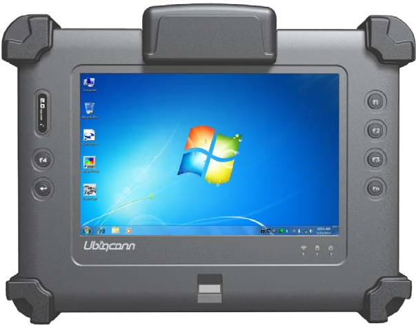
RuggedTabletPC
T70C
User’sGuide
FEDERAL COMMUNICATIONS COMMISSION INTERFERENCE
STATEMENT
This equipment has been tested and found to comply with the limits for a Class B
digital device, pursuant to part 15 of the FCC Rules. These limits are designed to
provide reasonable protection against harmful interference in a residential installation.
This equipment generates, uses and can radiate radio frequency energy and, if not
installed and used in accordance with the instructions, may cause harmful
interference to radio communications. However, there is no guarantee that
interference will not occur in a particular installation. If this equipment does cause
harmful interference to radio or television reception, which can be determined by
turning the equipment off and on, the user is encouraged to try to correct the
interference by one or more of the following measures:
-Reorient or relocate the receiving antenna.
-Increase the separation between the equipment and receiver.
-Connect the equipment into an outlet on a circuit different from that to which the receiver is
connected.
-Consult the dealer or an experienced radio/ TV technician for help.
CAUTION:
Any changes or modifications not expressly approved by the grantee of this device
could void the user's authority to operate the equipment.
Thisdeviceisoperationin5.15–5.25GHzfrequencyrange,thenrestrictedinindoor
useonly,Outdooroperationsinthe5150~5250MHzisprohibit.
Thisdeviceisslaveequipment,thedeviceisnotradardetectionandnotad‐hoc
operationintheDFSband.
Labelingrequirements
ThisdevicecomplieswithPart15oftheFCCRules.Operationissubjecttothe
followingtwoconditions:(1)thisdevicemaynotcauseharmfulinterference,and(2)
thisdevicemustacceptanyinterferencereceived, including interference that may
cause undesired operation.
RFexposurewarning
This equipment must be installed and operated in accordance with provided
instructions and must not be co-located or operating in conjunction with any
other antenna or transmitter. End-users and installers must be providing with
antenna installation instructions and transmitter operating conditions for
satisfying RF exposure compliance.
SAR Value: 1.298 W/kg
F
Fe
ea
at
tu
ur
re
es
s
Platform:
Intel®CedarTrailPlatform(N2600+NM10)
GPU:
IntelATOMN26001.6GHzDualcore
Chipset:
Intel®NM10ExpressChipset
SystemMemory:
2GBDDRIII800SO‐DIMMM
Storage:
‐1x32GSATASlimHalf‐SizeSolidStateDisk
LCDPanel:
7‐inchLEDBacklightScreen
7“XGA(1280x800)400nitsLCD,or500nitsLCD(option)
TouchPanel
5‐wireResistiveTouchScreen
Audio:
‐1xHighQualitySpeaker(2W)
‐InternalMicrophone:1xinfrontBezel
TPM:
1xCompatiblewithTPM1.2(option)
Communication:
‐10/100MbpsEthernet
‐Wi‐FiIEEE802.11a/b/g/n;Bluetooth4.0
GPSPositioning:
‐ GPS/QZSS,GLONASS
‐ 50channelall‐in‐viewtracking
Webcam:
Front‐2Mega‐pixelCamera
Rear‐5Mega‐pixelCamerawithLEDFlashlight
ExternalI/O:
2xUSB2.0(type‐A),1xMicroSDslot,1xRS232
PowerAdapter:
ACInput,100V~240VAC,50~60Hz
DCOutput,19VDC@3.42A,65W
Battery
InternalBattery‐SmartLithiumPolymerBattery,2900mAH,7.5V
Mechanical & Environmental
Physical Characteristics :
Dimension & Weight :
225 x 168 x 26.5mm ; 850g
Rugged Design
Drop :
5ft drop (MIL-STD-810G Method 516.6 Procedure IV) METAL
Vibration :
Operating : MIL-STD-810G Method 514.6 Category 4 Fig 514.6C-1、C-2、C-3
Non-Operating : MIL-STD-810G Method 514.6 Category 24, Fig 514.6E-1
Mechanical Shock :
Operating : 40g, 11ms, Terminal sawtooth
Non-operating : 75g, 8~13ms, Terminal sawtooth
Water/Dust Resistance :
IP65
Environment :
Operation temperature : -20°C to +50°C
Storage Temperature : -30°C to +70°C
Humidity : 5-95% without condensation
Optional : External Accessories
External Battery Kits :
External Battery Pack :
Hot-swappable Lithium Polymer battery pack - doubles duration of mobile
operation, 4200mAh (2S1P), 7.4V
External Battery Charger :
Recharges external battery pack
MSR :
Reference Standards :
ANSI/ISO Standards 7810,7811-1/6, 7813
JIS II
Decoding Method :
ISO Track1 - IATA , Track2 - ABA and Track3 – THRIFT
Barcode Scanner :
Decoded Mode :
1D Symbologies : EAN/UPC, RSS, Code 39, Code 128, UCC/EAN 128, ISBN,
ISBT, Interleaved, Matrix, Industrial and Standard 2 of 5, Codabar, Code
93/93i, Code 11, MSI, Plessey, Telepen, postal codes.
2D Symbologies: Data Matrix, PDF417, Micro PDF 417, Maxicode, QR,
Aztec, EAN.UCC composite.
G
Ge
et
tt
ti
in
ng
g
t
to
o
k
kn
no
ow
w
y
yo
ou
ur
r
t
ta
ab
bl
le
et
t
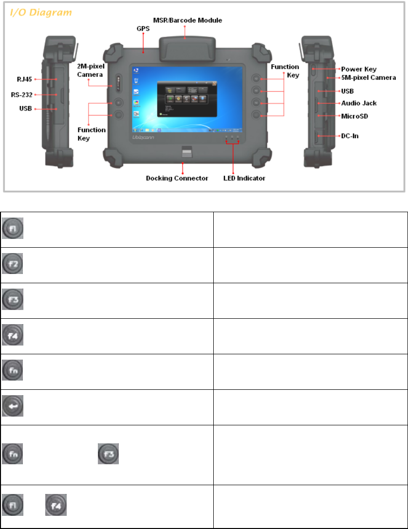
BeforestartingtosetuptheT70C,getfamiliarwiththelocationsandpurposeof
controls,connectorsandI/Oports,whichareillustratedinthefiguresbelow.When
placedupright,thefrontpaneloftheT70Cappearsasshowninbelow.
F1ButtonF1=WindowsFileexplorer
F2ButtonF2=WindowsMediaPlayer
F3ButtonF3=OnScreenkeyboard(osk)
F4ButtonF4=TaskManager
FnButtonFn=HotkeyUtility
EnterButtonEnterorReturnkey
FnButton+ F3Button
ImplementSecureAttentionSequence
(SAS),similarfunctionaspressing
Ctrl‐Alt‐Deletecombinationkeys.
or TriggerButton
F1orF4actsastriggerbuttonwhen
optionalbarcodescannerisinstalled.
Camera / 2 Mega-pixel (Front-facing)
The built-in camera can be used as a communication device for allowing you to
capture images, record videos, and have video chats. It is 2M pixels and can be used
for transmitting live image through network for video conference.
Camera / 5 Mega-pixel (Rear-facing)
The built-in high resolution camera can be used as a communication device for
allowing you to capture images, record videos, and have video chats.
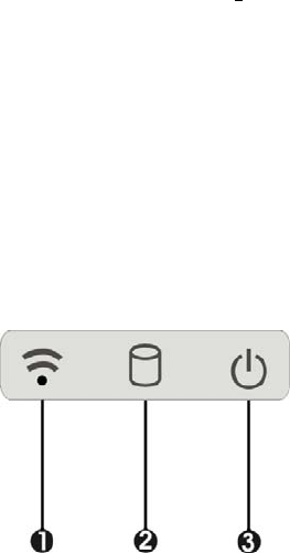
Power / Storage / RF status LED Indicator
Keeps you informed of your system’s current power status, storage access status, and
RF wireless devices ON/OFF status.
1. RF ON/OFF 2. Storage Access
3. Power LED Indicator
RF ON/OFF Indicator
When LED turns on, white LED indicates that a wireless device (Wifi / Bluetooth
/ WWAN) is activated. When LED turns off, it indicates that all RF devices are
being disabled.
Storage Access
When LED blinking white indicates that the system is accessing the internal
storage drive.
Power LED Indicator
Letting you know that system is turned on and indicate the battery charging
status.
Lights green when the system is powered on and battery is discharging
Lights amber when the system is powered on and battery is charging
Lights blinking amber when the system is in S3 sleep mode and battery
is charging or lights blinking green when the system is in S3 sleep mode
and battery is fully charged
Lights off when system is powered off or the battery is fully charged.
Power Button
Switch the computer power on and off, or resumes whenever it is in Suspend mode
(by OS define).
USB Ports
The two USB (type-A) ports allows you to connect USB 2.0-compliant devices (for
example, mouse, keyboard and so on) to your Tablet PC.

3.5mm Headphone Jack
Allows you to connect an external 3.5mm 4-conductor TRRS (stereo-plus-mic)
headphone for personal listening and sound recording.
MicroSD Card Slot
The MicroSD (SDHC) card slot allows you to transfer/record video and pictures to your
tablet, while adding extra storage capacity.
Ethernet Port
The 10/100Mbps Ethernet port allows you to connect to other computers/networks
through a local area network (LAN).
RS-232 Serial Port
RS-232 serial port allows connections to modems, printers, mice, barcode readers,
data acquisition equipment, and other peripheral devices.
Accessory Door
By removing the two long screws on top side of the system, allows you to install
optional snap-on module.
External Battery Connector
To install the external battery pack, install external battery holder first and remove the
cover of external battery connector before snap the battery pack into the external
battery connector.
Speaker
Integrated stereo speaker for sound and audio output for your multimedia
presentations or listening pleasure.
Protective Rubber
To prevent system harm from vibration or shock, the system is designed with installing
protective rubber on four corners.
Programmable Function Buttons (F1~F4)
These buttons is programmable to execute specific software application. When you
program the application to launch, please write this directory as listed below into the
configuration file, then the system will aware and execute this application.
[Setup]
F1_EXE="c:\windows\explorer.exe"
F1_PARA=""
F1_PATH=""
F2_EXE="C:\Program Files\Windows Media Player\wmplayer.exe"
F2_PARA="/prefetch: 1"
F2_PATH=""
F3_EXE="C:\WINDOWS\system32\osk.exe"
F3_PARA=""
F3_PATH=""
F4_EXE="C:\WINDOWS\system32\taskmgr.exe"
F4_PARA=""
F4_PATH=""
The configuration file is located under drive C: root directory as
"c:\FKeySet.txt"
Trigger Buttons (F1 / F4)
Please press F1 or F4 function keys to trigger to scan the barcode when the optional
barcode scanner snap-on module is installed.
If your system does not install this module, these buttons can be programmable to
execute specific software application. When you program your application, please
write this directory as listed below into your configuration file, then the system will
aware and execute this application.
F1_EXE="c:\windows\explorer.exe"
F1_PARA=""
F1_PATH=""
F4_EXE="C:\WINDOWS\system32\taskmgr.exe"
F4_PARA=""
F4_PATH=""
DC-Jack
Lets you connect the AC power adapter in supplying continuous power to your Tablet
PC and recharging the battery.
TheACadapterprovidesexternalpowersourcetoyoursystemandchargesthe
internalbatterypackatthesametime.TheACadapteralsohasan
auto‐switchingdesignthatcanconnecttoany100VAC~240VACpoweroutlets.
Toconnectthepoweradapter:
1. Plug the AC adapter connector to the DC-Jack socket on the left side of the system.
2. Plug the power cord to the AC adapter.
Plug the other end of the power cord to a live wall outlet, at the same time, the
Power LED at front panel lights up.
‐‐ Forthepowersupplyofthisequipment,anapprovedpowercordhas
tobeused.
‐‐ Makesurethesocketandanyextensioncord(s)youusecansupport
thetotalcurrentloadofalltheconnecteddevices.
‐‐ Removeallpowerfromthedevicepriortoinstallingorremovingany
accessories,hardware,orcables
‐‐ Beforecleaningthesystem,makesureitisdisconnectedfrom
anyexternalpowersupplies(i.e.ACadapter).
Docking Connector
Lets you connect the system to docking station to dock the tablet PC when you are at
home or office desk.
U
Us
si
in
ng
g
t
th
he
e
H
Ho
ot
tk
ke
ey
y
U
Ut
ti
il
li
it
ty
y
A
Ap
pp
pl
li
ic
ca
at
ti
io
on
n
YourT70Ctablethasnumbersofapplicationsonthecontrolpanelforexecuting

specificcommand.Itprovidesyoutoadjustbrightness,volume,launchwebcam,
switchmonitor(viadocking)andRFdeviceON/OFF.
Thisuserinterfaceprovidesspecificmobileutilitytoletyoueasilysetupsome
helpfulfunctionsandawarethesystemstatusdirectly.
Thisutilityalsoletyouadjustsomefunctiontofittherequirements,suchas
brightnessandvolumeadjustment,webcamlaunch,monitorswitchingandRF
deviceON/OFF.
Furthermore,italsoprovidessysteminformationforyourreference,suchas
batterystatus,RFsettingwithitssignalstrength,firmware(BIOS&EC)version
information.Besidesthesefeatures,youcanpressthesoftbuttontohibernate
thissystem.
A
Ab
bo
ou
ut
t
t
th
he
e
U
Us
se
er
r
I
In
nt
te
er
rf
fa
ac
ce
e
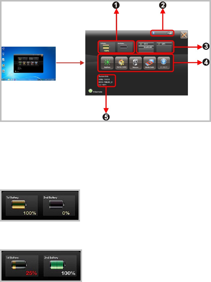
Enable or disable the User Interface
TodisplaytheUserInterface,pleasepresstheFnbuttonorpointtheHotkey
UtilityiconlocatedonWindowsdesktop.
ToclosetheUserInterfacefunction,pleasepresstheXbuttononthetopright
corneronthisUserInterfacefordisablingthisutilityfromthescreen.
Ifthereisnoactionwithinthisutilityin5seconds,theUIscreenwillclose
automatically.
System Status Information
Thisutilityshowsyouthebatterycapacitystatus,RFstatuswithitssignal
strengthandsysteminformation,andprovidesthecontrolpanelforthefunction
setting.
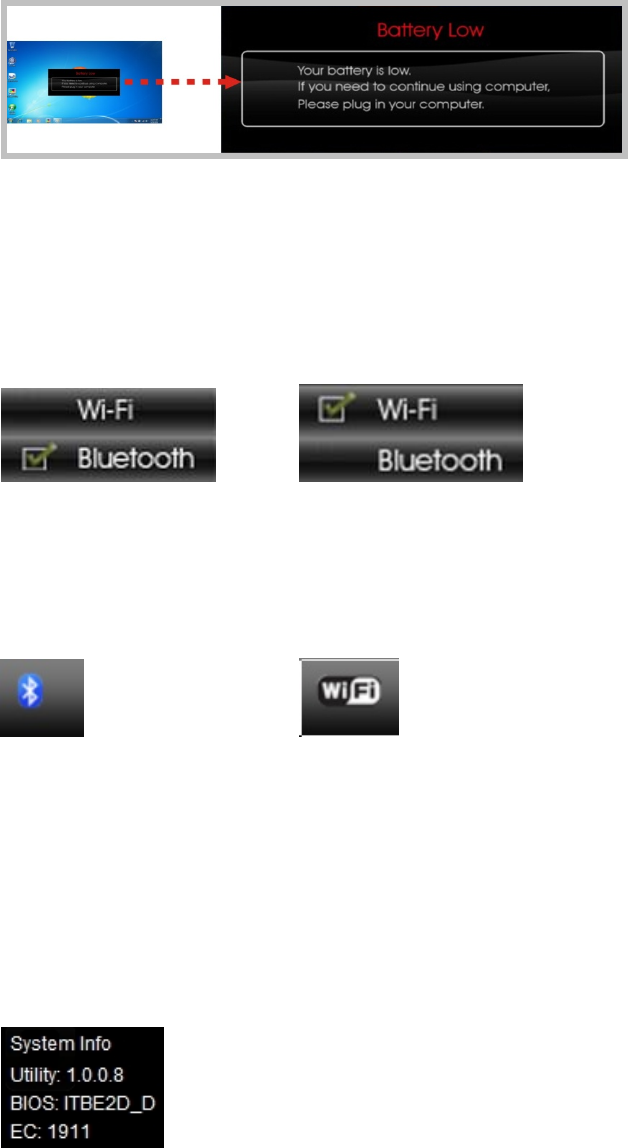
Forbatterycapacitystatus:
The
T70Cisequippedwithoneinternalbatteryandoneoptionalexternal
battery.
Thebatterycapacitystatusshownbelowadvisesyou,thatonlyoneinternal
batteryisembeddedwiththesystemwhichisfullycharged,andthereisno2nd
optionalbatteryinstalledinthesystem.
Ifthesysteminstallsboththe1stinternalbatteryand2ndoptionalbattery,the
illustrationshownbelowindicatesitscurrentchargingstatusandcapacity.
If1stbatterycapacitydropsto15%,thesystemwilldisplaythefollowingwarning
messagefor5seconds.
ForRFstatus:
ThefollowingRFstatusshowsyouthatthesystemisequippedwithWi‐Fi,or
Bluetoothfunctions.EitherWi‐FiorBluetoothfunctionisoperationintheT70C,
ifyouwanttoclosethefunction,pleaserefersectionforhowtodisableit.
ThefollowingsignalstrengthshowsyouthattheWi‐Fifunctionisconnecting
currently,thestrongerthesignalstrength,themorescalewillshowonthebar.If
thereisnomoduleinthesystem,therewillbenostatusscaleinthefollowing
statusbar.
ForSystemInformation:
Thesysteminformationshownontheleftshowsyouthehotkeyutilityversion,
BIOSandECversionandyoucanusethemforcustomerservicewhenasked.
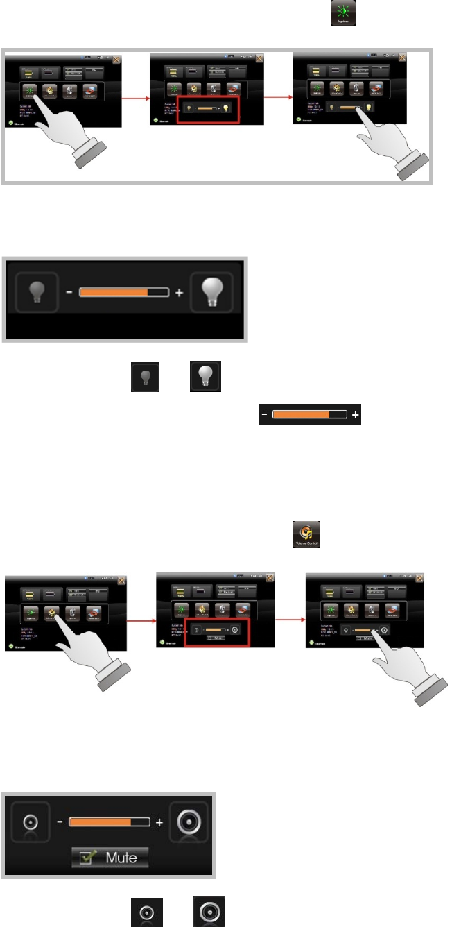
Brightness Control
Forbrightnessadjustment,presstheBrightness icon.
Whenyoupressit,thebrightnesscontrolpanelisappearedasfollows:
Youcanclick or toreduceorincreasetheLCDbrightness.
Also,youcanslidethescalebar tosetthebrightness.
Volume Control
ForVolumeadjustment,presstheVolume icon.
Whenyoupressit,theVolumecontrolpanelisappearedasfollows:
Youcanclick or toreduceorincreasetheaudiovolume
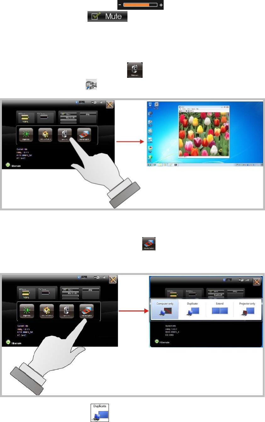
incrementally.
Also,youcanslidethescalebar tosettheaudiovolume.
YoucanticktheMute tomutetheaudio.
Launch Webcam Utility
ForWebcamLaunch,presstheWebcam icontolaunchtheWebcamutility.
OrcanaccesstheWebcam iconlocatedondesktop.
Monitor Switch
ForMonitorswitch,presstheMonitorSwitch topop‐uptheselectionbar
forchoosingthedisplaymodewithinfollowingfouroptions.
YoucanclickDuplicatetodisplaythesamecontentsbothonthe
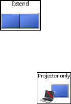
screenandexternaldisplaydevice.Theresolutiononthesetwodisplay
modesaresame,itisnotavailabletoadjusttheresolutionontheexternal
displaymode.
YoucanclickExtend todisplaythedifferentcontentsonthe
screenandexternaldisplaydevice.Youonlycanadjusttheresolutionon
theexternaldisplaydevice.
YoucanclickProjectoronly todisplayonexternal
projector/monitoronly.
P
Po
ow
we
er
ri
in
ng
g
o
on
n
f
fo
or
r
t
th
he
e
f
fi
ir
rs
st
t
t
ti
im
me
e
ThePower/ResumebuttonisfoundontheleftsideoftheTabletPC.Pressthe
Power/ResumebuttontostartyoursystemandcheckthatifthePowerLEDturns
on.
Afterafewseconds,thesystem’sdisplaywillturnonandyoursystemwillbegin
toexecutethePowerOnSelfTestorPOSTtocheckifallsystemcomponentsare
runningproperly.Anyerrorfoundduringthetestwillbedisplayedonthescreen.
Afterthetest,thescreenwillalsodisplayamessage"press<F2>toenterSETUP".
Youdon’tneedtorunthisprogramatthemomentasyourdealeralreadymade
thenecessarysettingsforyourcomputeroptimaloperation.
After the test has completed, your computer will start to search and boot up the
operating system from your hard drive.
Before setting up the system, please make sure the following items are available.
Keyboard
Mouse (for system software installation)
A keyboard is an input device; a mouse is a pointing device. Please connect these two
devices as graphics shown below to interact with your system.
U
Us
si
in
ng
g
t
th
he
e
U
US
SB
B
P
Po
or
rt
ts
s
USB(UniversalSerialBus)isahardwareinterfacethatenablesyoutoconnect
multipledevices(suchasprinters,mice,keyboards,storagedevices,joysticks,
digitalcameras,andvideoconferencecameras,etc.)toyourtabletpcandupto
127devicescanbeattached.Besides,USB’shotswapcapabilityallows
everythingtobepluggedinandunpluggedwithoutturningthesystemoff.
USB2.0isfullybackwardcompatible,youwillbeabletouseanUSB1.1devicein

anUSB2.0compliantsystem.
1. Connect the external device to the system.
2. The USB ports support hot plug-in connections. Install the device driver before using
the device.
U
Us
si
in
ng
g
t
th
he
e
E
Ex
xt
te
er
rn
na
al
l
A
Au
ud
di
io
o
S
Sy
ys
st
te
em
m
AttherightsideofyourTabletPC,youwillfindtheheadphonejackfor
connecting3.5mm4‐conductorTRRS(stereo‐plus‐mic)headphonejack.
Toconnecttoaheadphonejack:
1. Locate the headphone jack that you want to use to the target device.
2. Plug the jack into the port on the right side of the tablet.
B
Bi
io
os
s
S
Se
et
tu
up
p
P
Pr
ro
og
gr
ra
am
m
ThissystemcomeswithachipfromPhoenixBIOSthatcontainstheROMSetup
informationforyoursystem.(Thischipservesasaninterfacebetweentheprocessor
andtherestofthesystemcomponents.)Thissectionexplainstheinformation
containedintheSetupprogramandtellsyouhowtomodifythesettingsaccordingto
yoursystemconfiguration.
TheSetuputilityprogramallowsupdatestothemainboardconfigurationsettings.
TheBIOSsetupvalueswillbesavedintheCMOS.Itisexecutedwhenyouchangethe
systemconfiguration,youchangethesystembackupbattery,orthesystemdetectsa
configurationerrorandasksyoutoruntheSetupprogram.Youmusthaveconnected
aUSBtypeofkeyboard,andUsethearrowkeystoselect,andpressEntertorunthe
selectedprogram.
Function Key
Pleasecheckthefollowingtableforthefunctiondescriptionofeachdirectionkey.
Function Key (s) Function Description
/ Moves cursor left or right to select menu on menu bar.
/ Moves cursor up or down to select items
+ / - To change option for the selected items
<Tab> To bring up the selected screen
<F1> To display the General Help screen
<F9> To load bios setup defaults value.
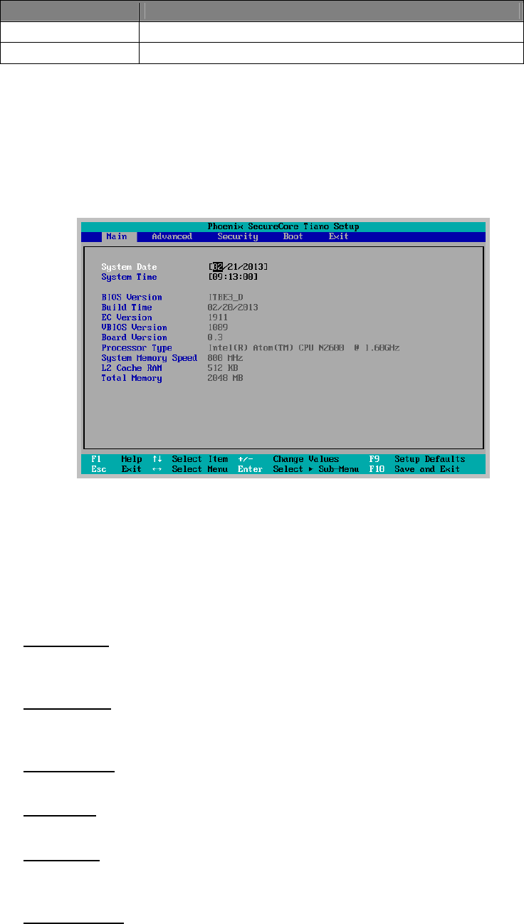
Function Key (s) Function Description
<F10> To save changes and exit the BIOS SETUP UTILITY
<ESC> To jump to the Exit Screen or exit the current screen
M
Ma
ai
in
n
S
Sc
cr
re
ee
en
n
S
Se
et
tu
up
p
U
Ut
ti
il
li
it
ty
y
WhenyouentertheBIOSSETUPUTILITY,theMainscreenwillappearanddisplay
thesystemoverview.
The Standard CMOS Setup screen is displayed above. Each feature may have one or
more option settings. Use the arrow keys to highlight the feature you want to change and
then use “”or “” to select the value you want for that feature.
NOTE: The system BIOS automatically detects EC version, board version, Processor,
memory size, thus no changes are necessary.
System Date
To set the date, highlight the Date field and then press +/- keys to set the current date.
Follow the month, day and year format.
System Time
To set the time, highlight the Time field and then press +/- keys to set the current time.
Follow the hour, minute, and second format.
BIOS Version
The system will automatically displays the information of BIOS version.
Build Time
The system will automatically displays the build time of BIOS.
EC Version
The system will automatically displays the information of EC (Embedded Controller)
firmware version.
VBIOS Version
The system will automatically displays the information of VBIOS version of internal
graphics.
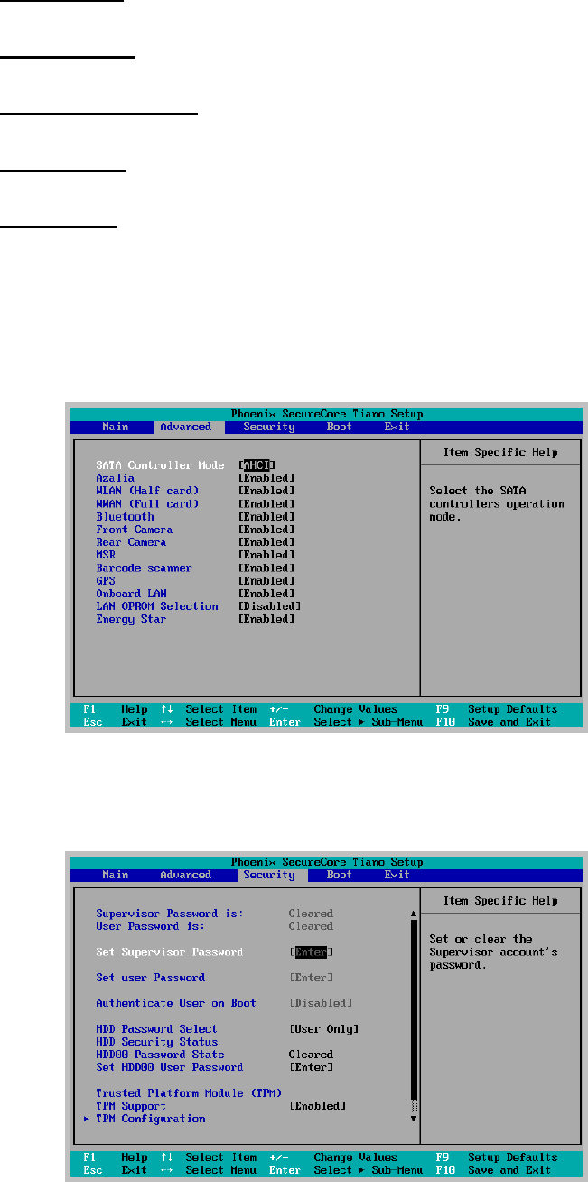
Board Version
The system will automatically displays the information of PCB version of mainboard.
Processor Type
The system will automatically displays the information of Processor Type and speed.
System Memory Speed
The system will automatically displays the information of System Memory Speed.
L2 Cache RAM
The system will automatically displays the information of L2 Cache RAM.
Total Memory
The system will automatically displays the information of Total Memory.
A
Ad
dv
va
an
nc
ce
ed
d
B
BI
IO
OS
S
F
Fe
ea
at
tu
ur
re
es
s
For Advanced Settings, it lets you define the device configuration when system booting.
S
Se
ec
cu
ur
ri
it
ty
y
C
Co
on
nf
fi
ig
gu
ur
ra
at
ti
io
on
n
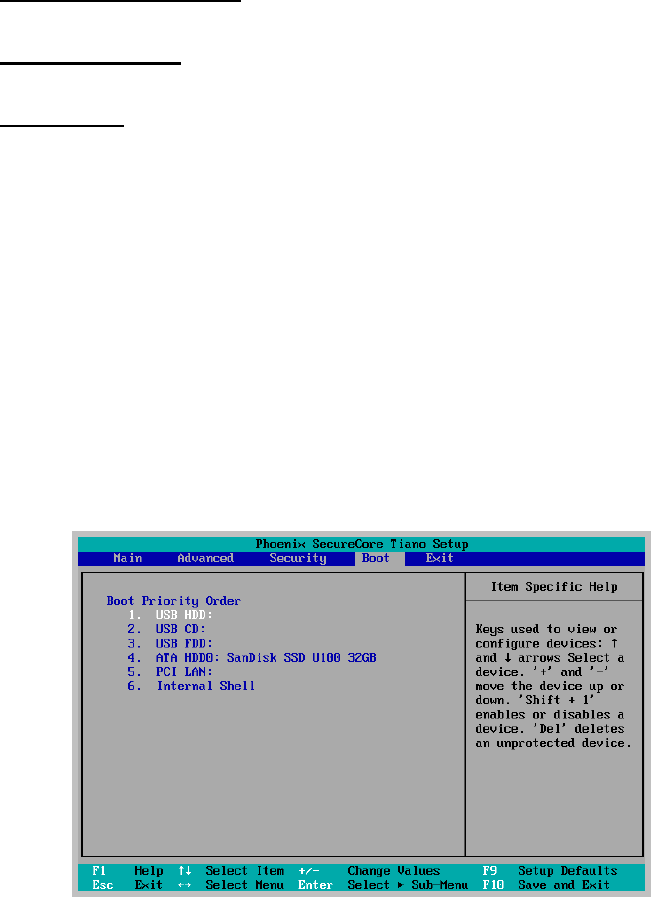
Set Supervisor Password
This field let you set or clear the Supervisor account’s password.
Set User Password
This field let you set or clear the User account’s password.
TPM Support
Lets you activate or de-activate the TPM function by selecting Enabled or Disabled
option. (For the non-TPM SKU, this item will display “no detected”.)
B
Bo
oo
ot
t
M
Ma
an
na
ag
ge
em
me
en
nt
t
S
Se
et
tu
up
p
Thispageallowsyoutosetthesearchdrivesequencewherethesystemwilltry
tobootupfirst.
Toselectthebootdevice,youcanusetheupordownarrowkey,thenpress<+>
tomoveupthedeviceinthelistorpress<‐>tomovedownthedeviceinthelist.
Toexitfromthismenu,press<Esc>.
E
Ex
xi
it
t
C
Co
on
nt
tr
ro
ol
l
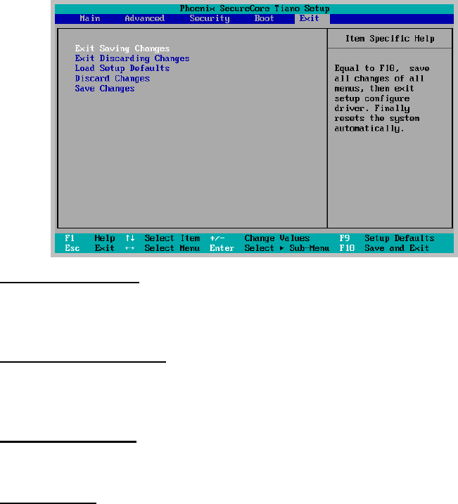
Exit Saving Changes
When you select this option, it will pop-out the following message, “Save configuration
changes and exit setup?” Select [OK] to save the changes and exit the BIOS SETUP
UTILITY.
Exit Discarding Changes
When you select this option, it will pop-out the following message, “Discard changes
and exit setup?”. Select [OK] to exit the BIOS SETUP UTILITY without saving any
changes.
Load Setup Defaults
When you select this option, it will pop-out the following message, “Load optimal
defaults?” Select [OK] to load the default values for all the setup configurations.
Save Changes
When you select this option, it will pop-out the following message, “Save changes?”
Select [OK] to save all changes.
M
Ma
ai
in
nt
ta
ai
in
ni
in
ng
g
t
th
he
e
B
Ba
at
tt
te
er
ry
y
Donotexposeheatorattempttodisassemblethebattery,anddonotplace
thebatteryinwaterorinafire.
Donotsubjectthebatterytostrongimpact,suchasablowfromahammer,
orsteppingonordroppingit.
Donotpunctureordisassemblethebattery.
Donotattempttoopenorservicethebattery.
Replaceonlywithbatteriesdesignedspecificallyforthisproduct.
Keepthebatteryoutofreachofchildren.
Disposeofusedbatteriesaccordingtolocalregulations.
M
Ma
ai
in
nt
ta
ai
in
ni
in
ng
g
t
th
he
e
L
LC
CD
D
D
Di
is
sp
pl
la
ay
y
Onlyoperatetouchpanelusingapolyacetalstyluspen(tipR0.8mmor
more)orafinger.
Donotscratchthesurfaceofthescreenwithanyhardobjects.
Donotoperatetouchpanelwithhardorsharptipssuchasaballpointpen
oramechanicalpencilasitwouldmakepermanentscratchtothesurface
oftouchscreen.
Donotspraycorrosiveliquiddirectlyonthescreenorallowexcessliquidto
dripdowninsidethedevice.
Donotplaceanything,suchasfoodanddrink,onthescreenatanytimeto
preventdamagetothescreen.
CleantheLCDdisplayonlywithasoftclothdampenedwithdenatured
alcoholoraproprietaryLCDscreencleaner.
C
Cl
le
ea
an
ni
in
ng
g
t
th
he
e
T
Ta
ab
bl
le
et
t
Turnoffthetabletandunplugthepowercord.
Wipethescreenandexteriorwithasoft,dampclothmoistenedonlywith
water.Donotuseliquidoraerosolcleanersonthescreen,asthesewill
discolorthefinishanddamagethescreen.