Ubiquiti AF5LTU Digital Transmission Radio User Manual airFiber AF LTU Quick Start Guide
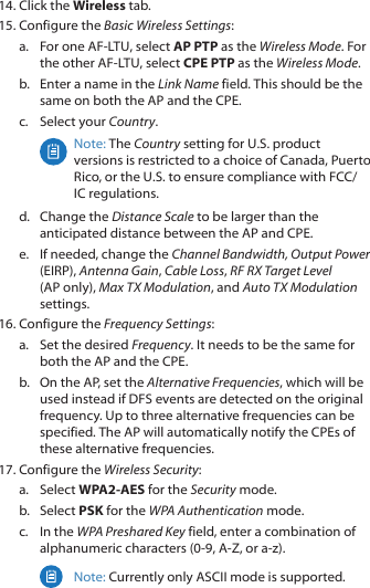
Ubiquiti Networks, Inc. Digital Transmission Radio airFiber AF LTU Quick Start Guide
Ubiquiti >
Contents
- 1. User Manual
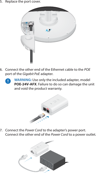
- 2. user manual
User Manual
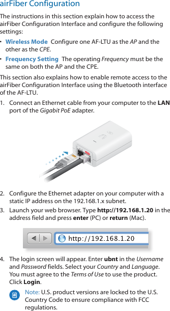
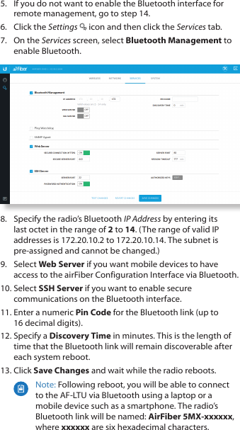
![Declaration of Conformityбългарски [Bulgarian] С настоящото UBIQUITI NETWORKS декларира, че този тип радиосъоръжение AF‑LTU е в съответствие с Директива 2014/53/ЕС. Цялостният текст на ЕС декларацията за съответствие може да се намери на следния интернет адрес: www.ubnt.com/complianceHrvatski [Croatian] UBIQUITI NETWORKS ovime izjavljuje da je radijska oprema tipa AF‑LTU u skladu s Direktivom 2014/53/EU. Cjeloviti tekst EU izjave o sukladnosti dostupan je na sljedećoj internetskoj adresi: www.ubnt.com/complianceČeština [Czech] Tímto UBIQUITI NETWORKS prohlašuje, že typ rádiového zařízení AF‑LTU je v souladu se směrnicí 2014/53/EU. Úplné znění EU prohlášení o shodě je k dispozici na této internetové adrese: www.ubnt.com/complianceDansk [Danish] Hermed erklærer UBIQUITI NETWORKS, at radioudstyrstypen AF‑LTU er i overensstemmelse med direktiv 2014/53/EU. EU‑overensstemmelseserklæringens fulde tekst kan findes på følgende internetadresse: www.ubnt.com/complianceNederlands [Dutch] Hierbij verklaar ik, UBIQUITI NETWORKS, dat het type radioapparatuur AF‑LTU conform is met Richtlijn 2014/53/EU. De volledige tekst van de EU‑conformiteitsverklaring kan worden geraadpleegd op het volgende internetadres: www.ubnt.com/complianceEnglish Hereby, UBIQUITI NETWORKS declares that the radio equipment type AF‑LTU is in compliance with Directive 2014/53/EU. The full text of the EU declaration of conformity is available at the following internet address: www.ubnt.com/complianceEesti keel [Estonian] Käesolevaga deklareerib UBIQUITI NETWORKS, et käesolev raadioseadme tüüp AF‑LTU vastab direktiivi 2014/53/EL nõuetele. ELi vastavusdeklaratsiooni täielik tekst on kättesaadav järgmisel internetiaadressil: www.ubnt.com/complianceSuomi [Finnish] UBIQUITI NETWORKS vakuuttaa, että radiolaitetyyppi AF‑LTU on direktiivin 2014/53/EU mukainen. EU‑vaatimustenmukaisuusvakuutuksen täysimittainen teksti on saatavilla seuraavassa internetosoitteessa: www.ubnt.com/complianceFrançais [French] Le soussigné, UBIQUITI NETWORKS, déclare que l’équipement radioélectrique du type AF‑LTU est conforme à la directive 2014/53/UE. Le texte complet de la déclaration UE de conformité est disponible à l’adresse internet suivante: www.ubnt.com/complianceDeutsch [German] Hiermit erklärt UBIQUITI NETWORKS, dass der Funkanlagentyp AF‑LTU der Richtlinie 2014/53/EU entspricht. Der vollständige Text der EU‑Konformitätserklärung ist unter der folgenden Internetadresse verfügbar: www.ubnt.com/complianceΕλληνικά [Greek] Με την παρούσα ο/η UBIQUITI NETWORKS, δηλώνει ότι ο ραδιοεξοπλισμός AF‑LTU πληροί την οδηγία 2014/53/ΕΕ. Το πλήρες κείμενο της δήλωσης συμμόρφωσης ΕΕ διατίθεται στην ακόλουθη ιστοσελίδα στο διαδίκτυο: www.ubnt.com/complianceMagyar [Hungarian] UBIQUITI NETWORKS igazolja, hogy a AF‑LTU típusú rádióberendezés megfelel a 2014/53/EU irányelvnek. Az EU‑megfelelőségi nyilatkozat teljes szövege elérhető a következő internetes címen: www.ubnt.com/complianceÍslenska [Icelandic] Hér með lýsir UBIQUITI NETWORKS yfir því að AF‑LTU er í samræmi við grunnkröfur og aðrar kröfur, sem gerðar eru í tilskipun 2014/53/EU. Fullur texti ESB samræmisyfirlýsing er að finna á eftirfarandi netfangi: www.ubnt.com/complianceItaliano [Italian] Il fabbricante, UBIQUITI NETWORKS, dichiara che il tipo di apparecchiatura radio AF‑LTU èconforme alla direttiva 2014/53/UE. Il testo completo della dichiarazione di conformità UE è disponibile al seguente indirizzo Internet: www.ubnt.com/complianceLatvių kalba [Latvian] Ar šo UBIQUITI NETWORKS deklarē, ka radioiekārta AF‑LTU atbilst Direktīvai 2014/53/ES. Pilns ES atbilstības deklarācijas teksts ir pieejams šādā interneta vietnē: www.ubnt.com/complianceLietuvių kalba [Lithuanian] Aš, UBIQUITI NETWORKS, patvirtinu, kad radijo įrenginių tipas AF‑LTU atitinka Direktyvą 2014/53/ES. Visas ES atitikties deklaracijos tekstas prieinamas šiuo interneto adresu: www.ubnt.com/compliance](https://usermanual.wiki/Ubiquiti/AF5LTU.User-Manual/User-Guide-3727916-Page-30.png)
![Malti [Maltese] B’dan, UBIQUITI NETWORKS, niddikjara li dan it‑tip ta’ tagħmir tar‑radju AF‑LTU huwa konformi mad‑Direttiva 2014/53/UE. Id‑dikjarazzjoni tal‑konformità tista’ tiġi kkonsultata minn www.ubnt.com/complianceNorsk [Norwegian] UBIQUITI NETWORKS erklærer herved at utstyret AF‑LTU er i samsvar med de grunnleggende krav og øvrige relevante krav i direktiv 2014/53/EU. Den fulle teksten til EU‑samsvarserklæringen er tilgjengelig på følgende internettadresse: www.ubnt.com/compliancePolski [Polish] UBIQUITI NETWORKS niniejszym oświadcza, że typ urządzenia radiowego AF‑LTU jest zgodny z dyrektywą 2014/53/UE. Pełny tekst deklaracji zgodności UE jest dostępny pod następującym adresem internetowym: www.ubnt.com/compliancePortuguês [Portuguese] O(a) abaixo assinado(a) UBIQUITI NETWORKS declara que o presente tipo de equipamento de rádio AF‑LTU está em conformidade com a Diretiva 2014/53/UE. O texto integral da declaração de conformidade está disponível no seguinte endereço de Internet: www.ubnt.com/complianceRomână [Romanian] Prin prezenta, UBIQUITI NETWORKS declară că tipul de echipamente radio AF‑LTU este în conformitate cu Directiva 2014/53/UE. Textul integral al declarației UE de conformitate este disponibil la următoarea adresă internet: www.ubnt.com/complianceSlovenčina [Slovak] UBIQUITI NETWORKS týmto vyhlasuje, že rádiové zariadenie typu AF‑LTU je v súlade so smernicou 2014/53/EÚ. Úplné EÚ vyhlásenie o zhode je k dispozícii na tejto internetovej adrese: www.ubnt.com/complianceSlovenščina [Slovenian] UBIQUITI NETWORKS potrjuje, da je tip radijske opreme AF‑LTU skladen z Direktivo 2014/53/EU. Celotno besedilo izjave EU o skladnosti je na voljo na naslednjem spletnem naslovu: www.ubnt.com/complianceEspañol [Spanish] Por la presente, UBIQUITI NETWORKS declara que el tipo de equipo radioeléctrico AF‑LTU es conforme con la Directiva 2014/53/UE. El texto completo de la declaración UE de conformidad está disponible en la dirección Internet siguiente: www.ubnt.com/complianceSvenska [Swedish] Härmed försäkrar UBIQUITI NETWORKS att denna typ av radioutrustning AF‑LTU överensstämmer med direktiv 2014/53/EU. Den fullständiga texten till EU‑försäkran om överensstämmelse finns på följande webbadress: www.ubnt.com/complianceOnline ResourcesWebsite www.ubnt.com Support help.ubnt.comCommunity community.ubnt.comDownloads downloads.ubnt.com](https://usermanual.wiki/Ubiquiti/AF5LTU.User-Manual/User-Guide-3727916-Page-31.png)