Ubiquiti M2 802.11 b/g & n MIMO 2x2 outdoor radio User Manual user guide
Ubiquiti Networks, Inc. 802.11 b/g & n MIMO 2x2 outdoor radio user guide
UserManual.wiki
>
Ubiquiti
>
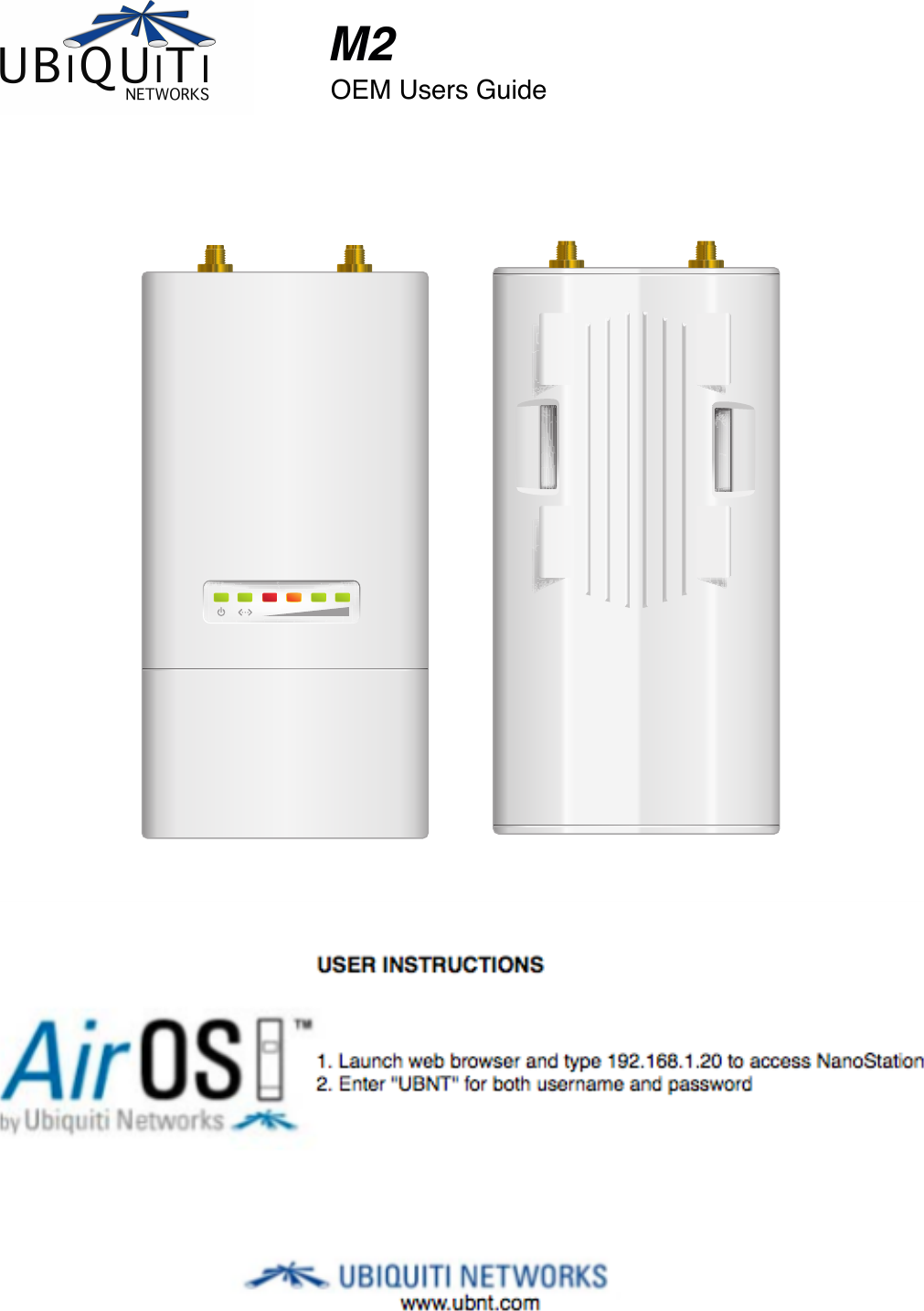
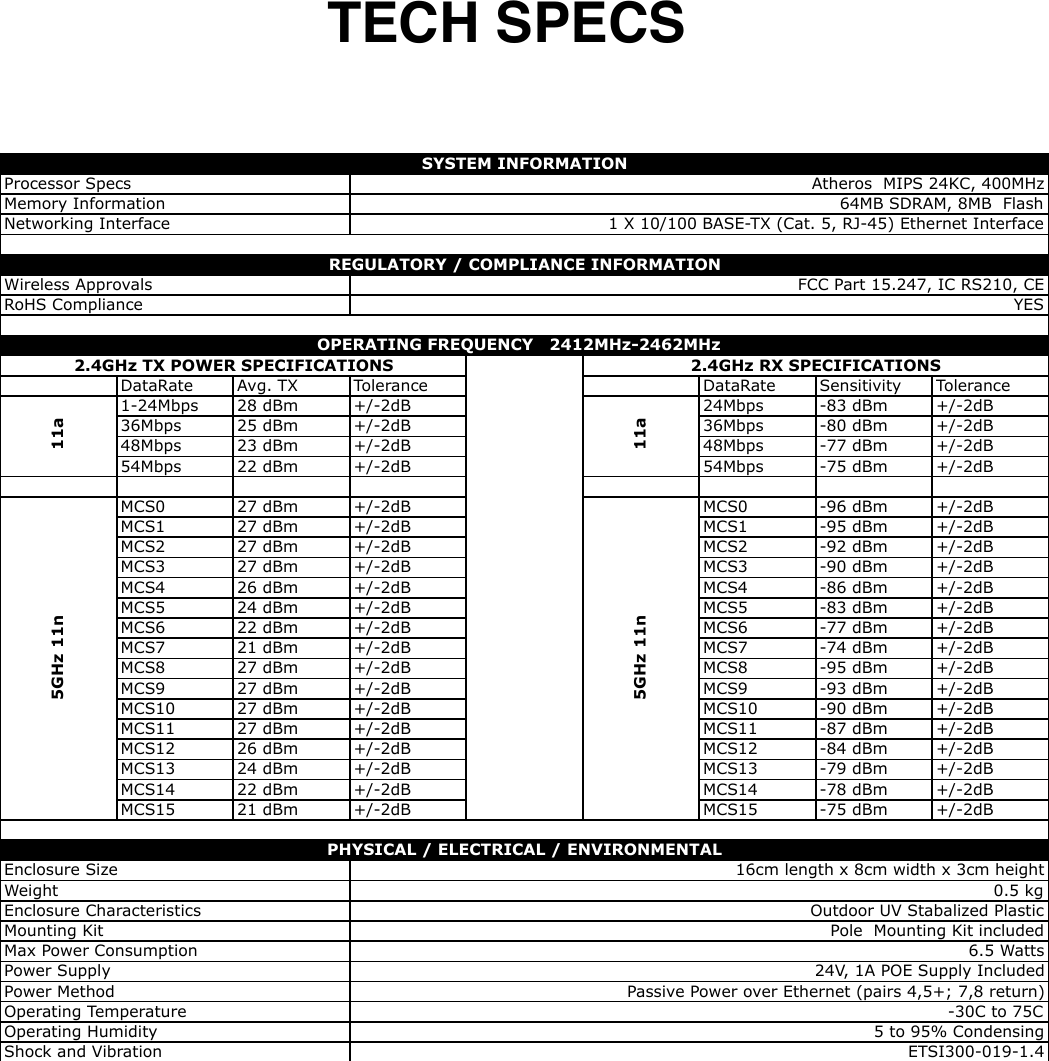
M2 User Manual
User Guide
Navigation menu
Upload a User Manual
Namespaces
Wiki Guide
HTML
PDF
Info
Views
User Manual
Discussion / Help
Navigation