Ubiquiti UAPRO 802.11abgn Access Point User Manual UniFi AP Pro User Guide
Ubiquiti Networks, Inc. 802.11abgn Access Point UniFi AP Pro User Guide
UserManual.wiki
>
Ubiquiti
>
UAPRO User Manual
User manual
Navigation menu
Upload a User Manual
Namespaces
Wiki Guide
HTML
PDF
Info
Views
User Manual
Discussion / Help
Navigation
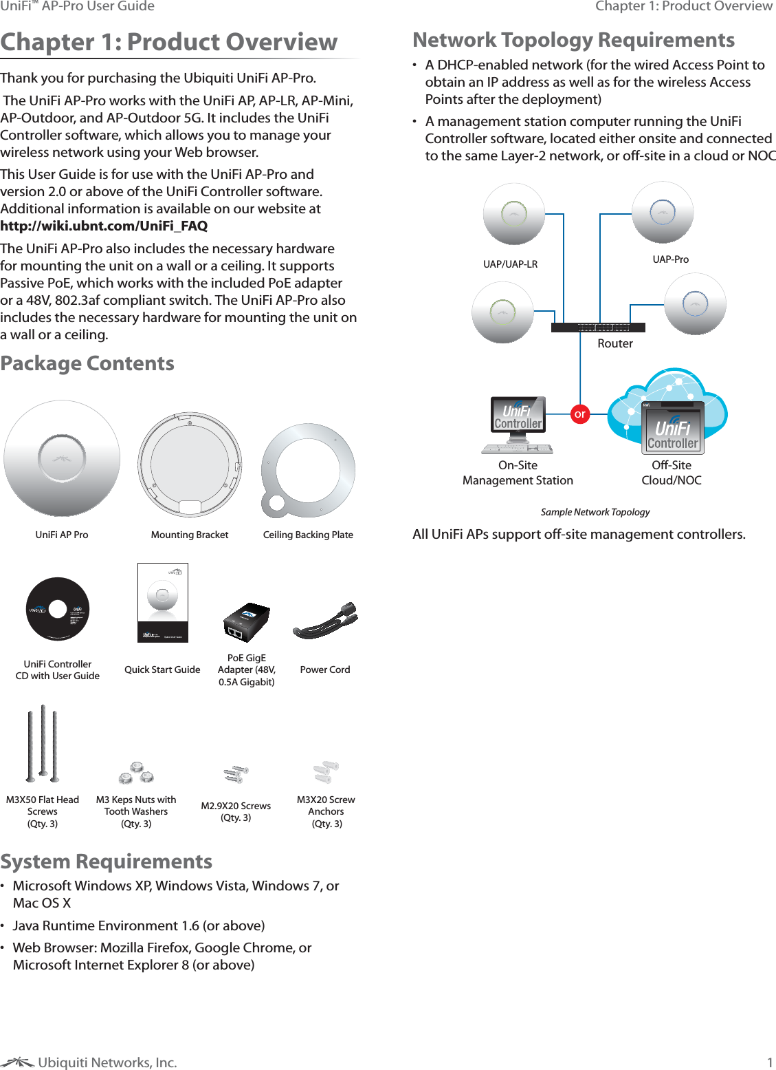
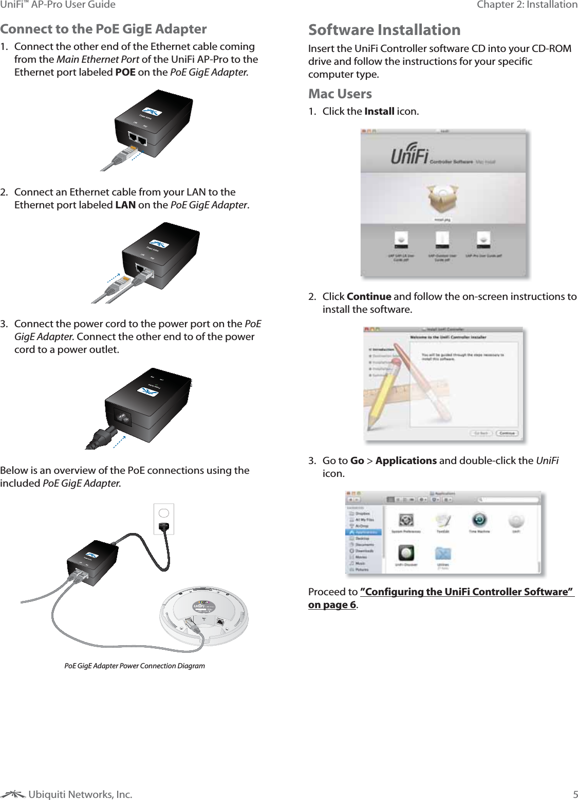
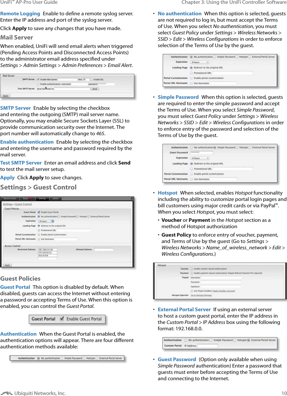
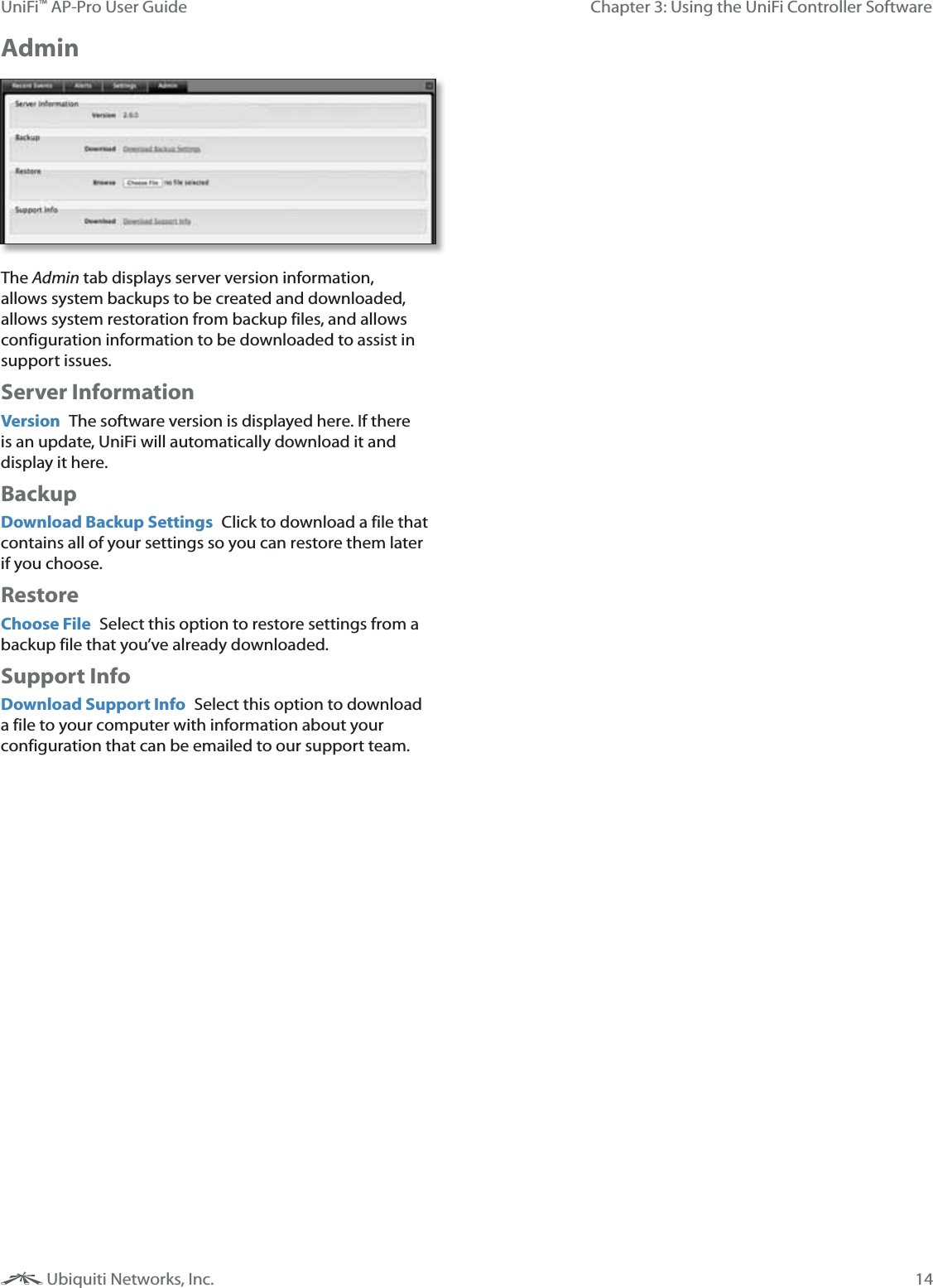
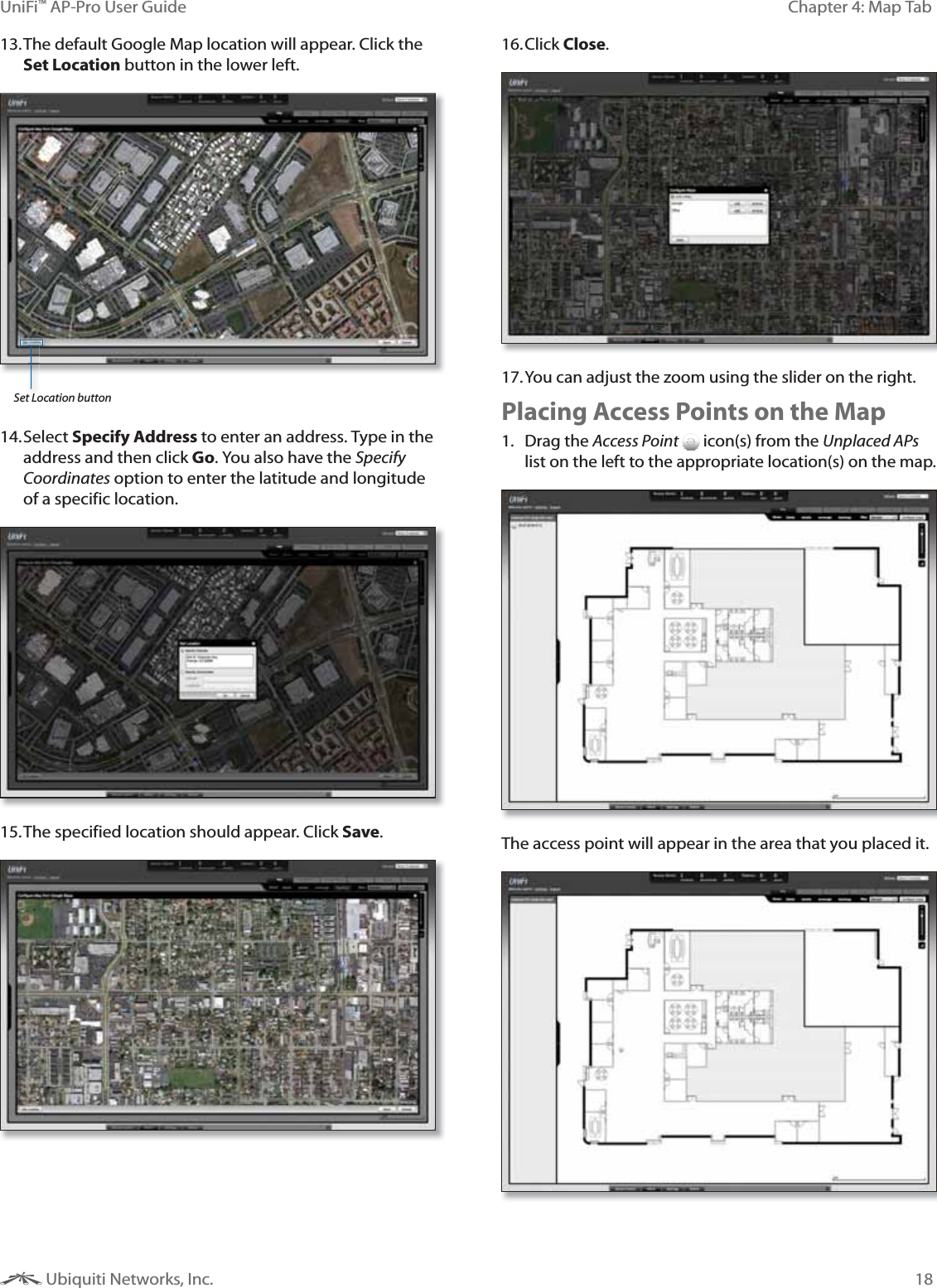
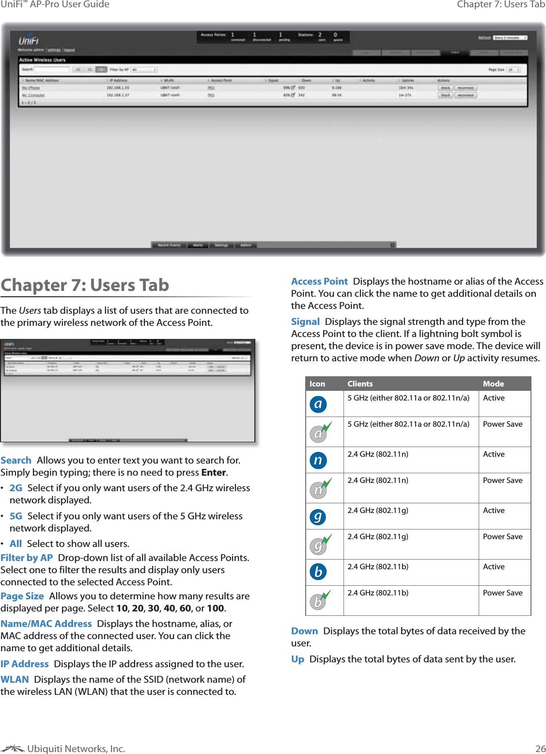
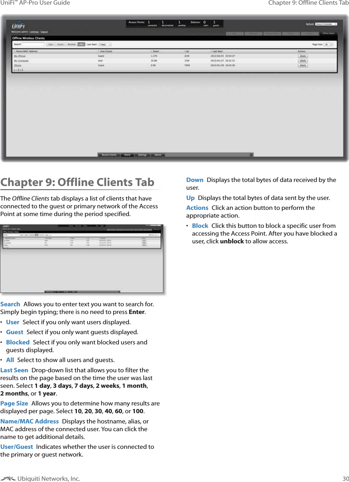
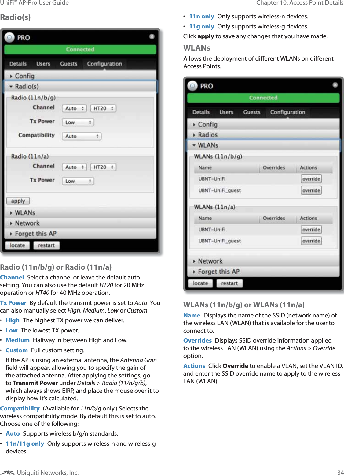
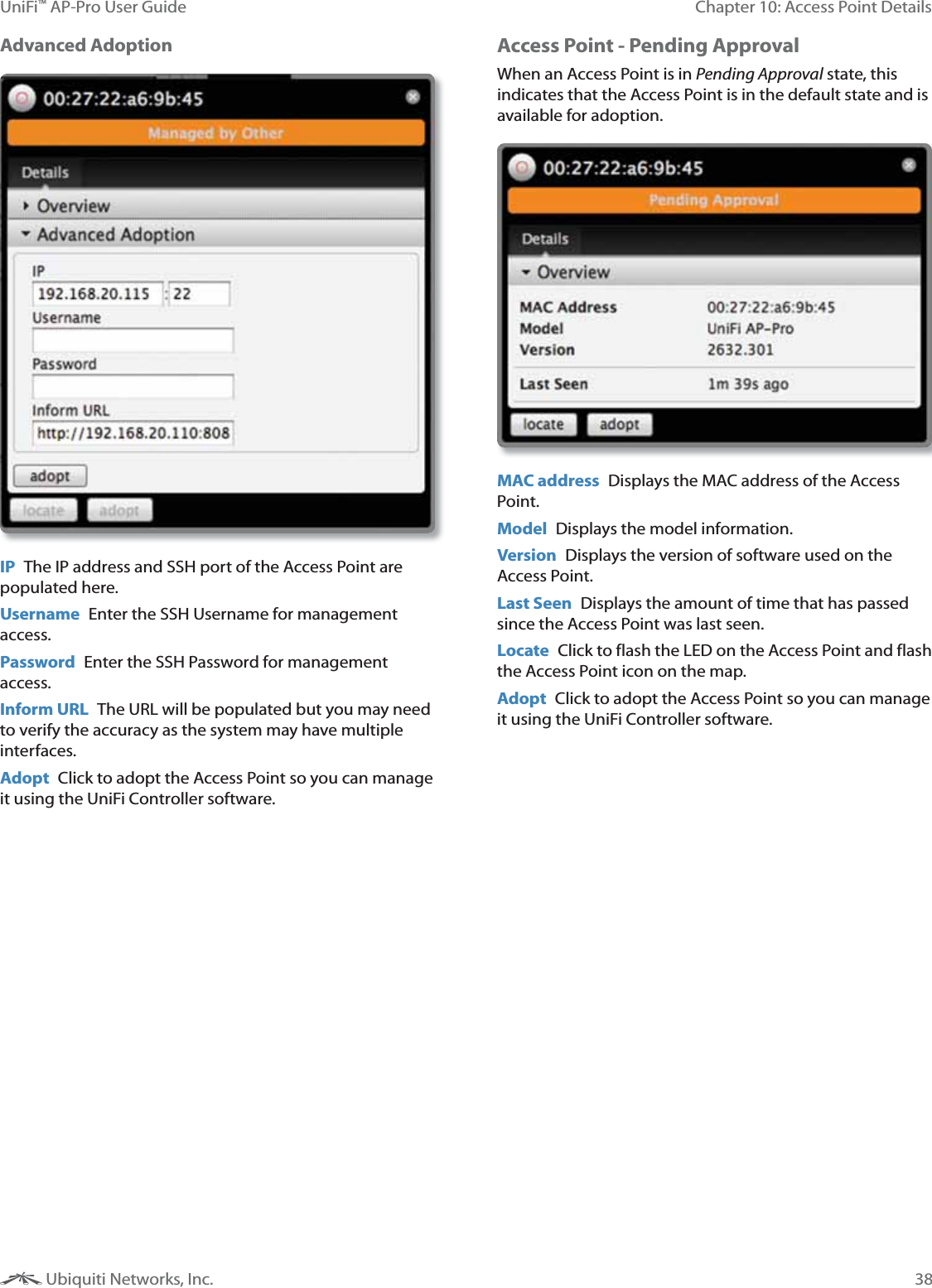
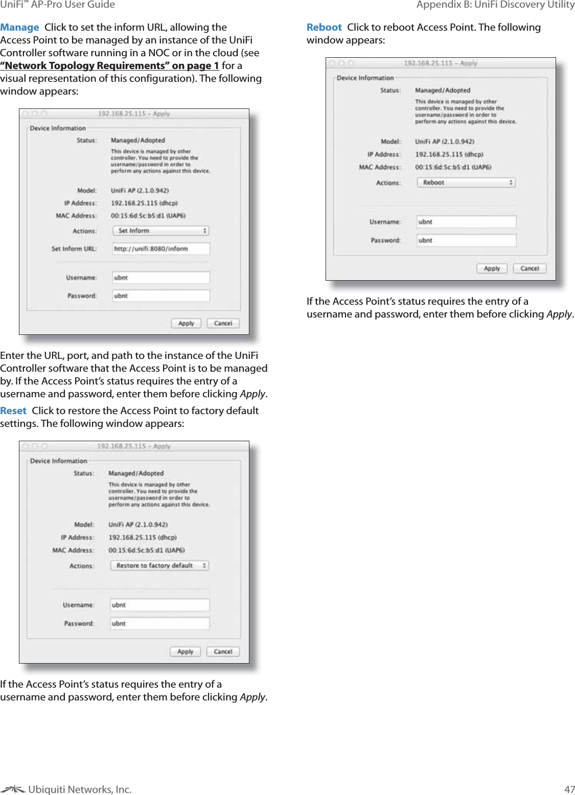
![8Chapter 3: Using the UniFi Controller SoftwareUniFi™ AP-Pro User Guide Ubiquiti Networks, Inc.Chapter 3: Using the UniFi Controller SoftwareThe UniFi Controller software that comes with your UniFi AP-Pro has a browser-based interface for easy configuration and management. To access the interface, perform the following steps:1. Launch the UniFi Controller application if hasn’t already been started. Mac users: Go > Applications > UniFi Windows users: Start > All Programs > Ubiquiti UniFi. 2. The UniFi login screen will appear. Enter the admin name and password in the appropriate fields and click Login. Interface TabsThe UniFi software consists of six primary tabs. This User Guide covers each tab with a chapter. For details, on a specific tab, refer to the appropriate chapter. “Map Tab” on page 15 “Statistics Tab” on page 22 “Access Points Tab” on page 24 “Users Tab” on page 26 “Guests Tab” on page 28 “Offline Clients Tab” on page 30Common Interface OptionsThe common interface options are accessible from all tabs in the UniFi interface. Access Points connected Drop-down clickable list of all of the Access Points that are online. disconnected Displays a list of Access Points that were previously online but are no longer accessible. pending Drop-down clickable list of all of the Access Points that are not yet managed but are available for management. Stations users Displays the total number of users connected to the primary network. guests Displays the total number of users connected to the guest network.Recent EventsDisplays a list of recent events including the date and time the event occurred and the details of the event. The User and Access Point names are clickable links. Event Slider Move the slider right and left to navigate between pages of events. Search Allows you to enter text you want to search for. Simply begin typing; there is no need to press Enter.Clicking on an Event Device LinkThe event messages have clickable links [in brackets underlined in gray text] for AP (see “Access Point Details” on page 31), User, and Guest (see “User/Guest Details” on page 40). Details vary based on the selection.](https://usermanual.wiki/Ubiquiti/UAPRO/User-Guide-1678420-Page-11.png)
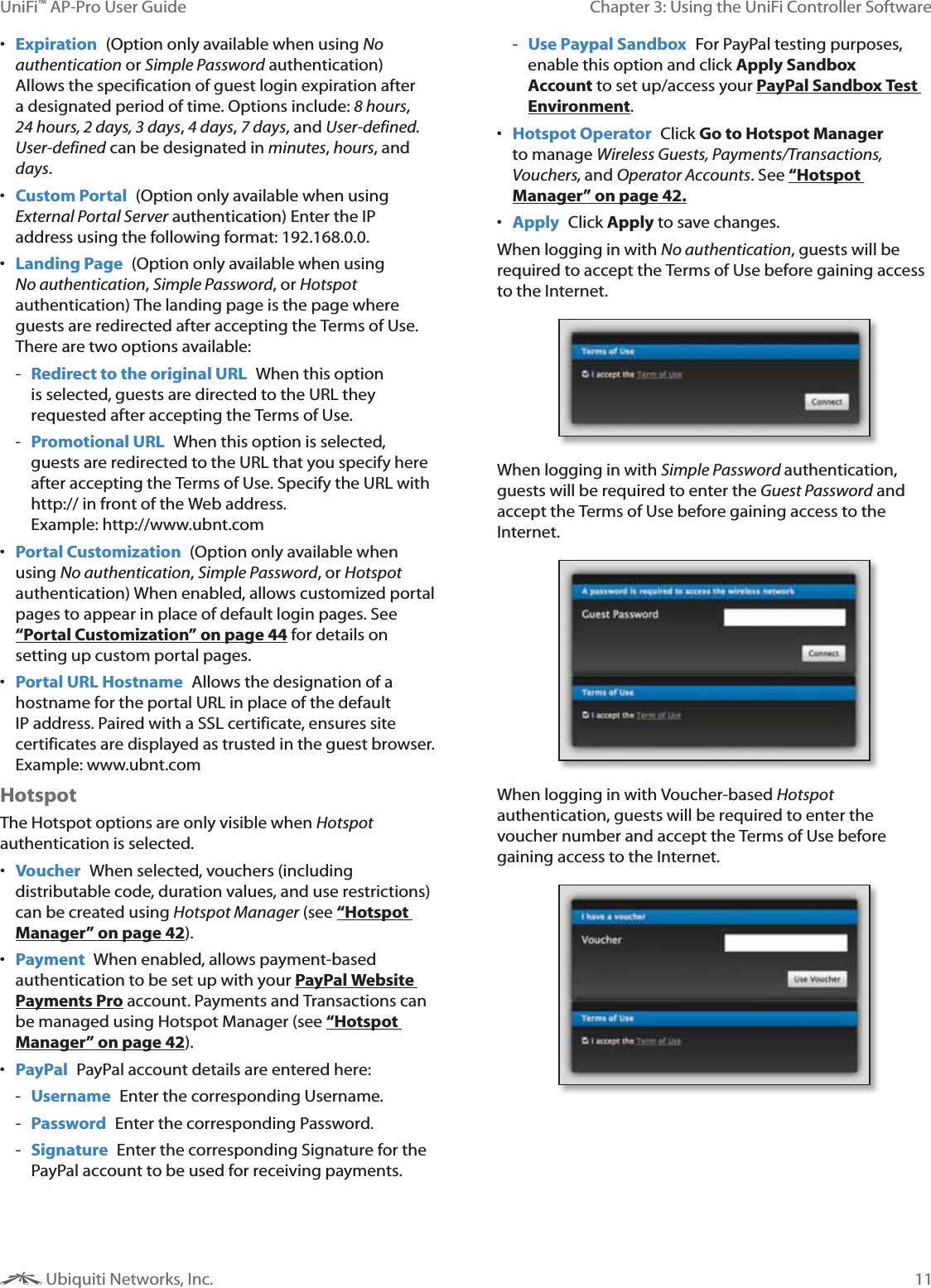
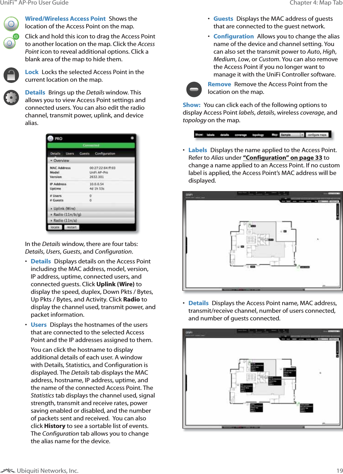
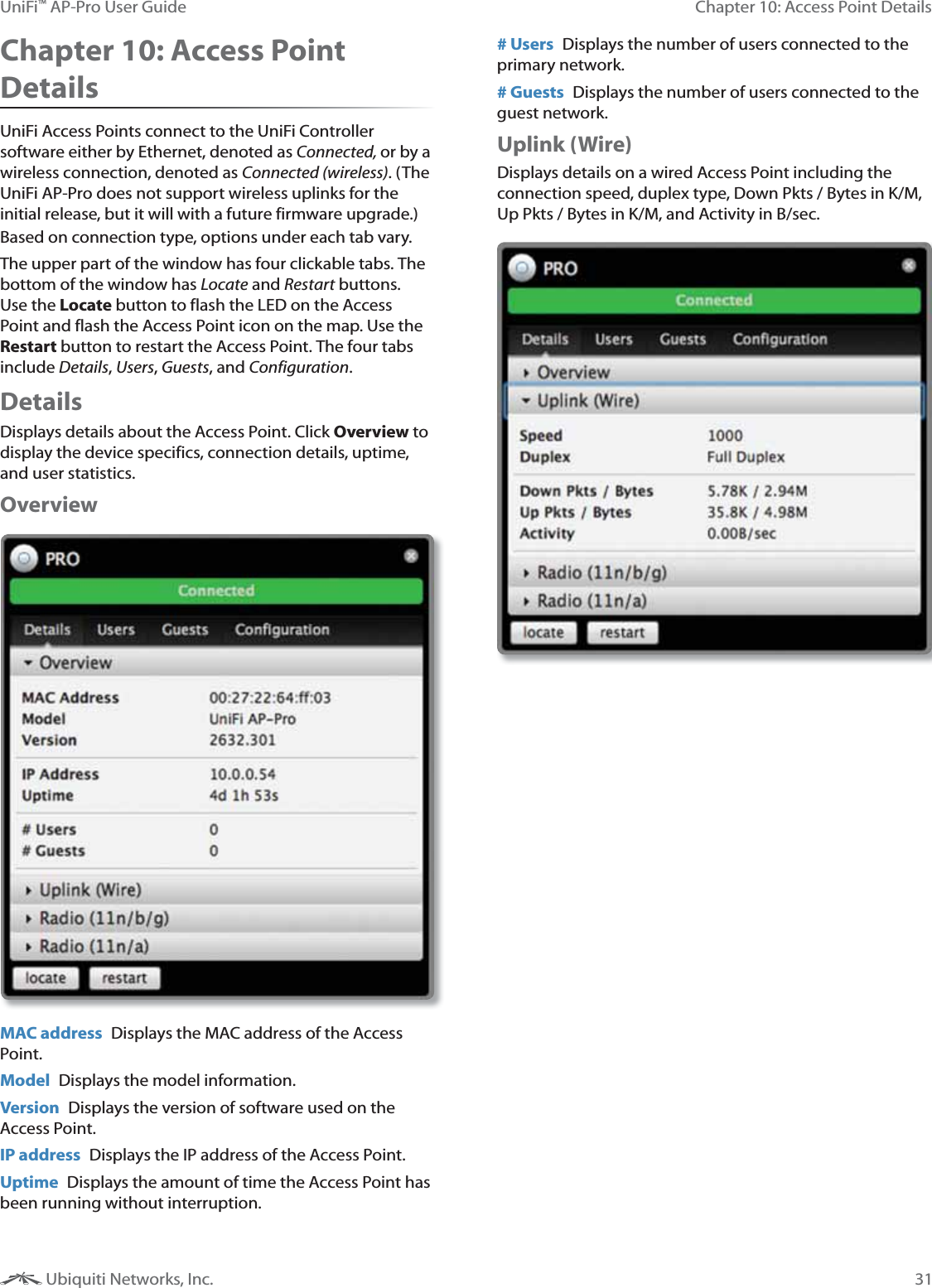
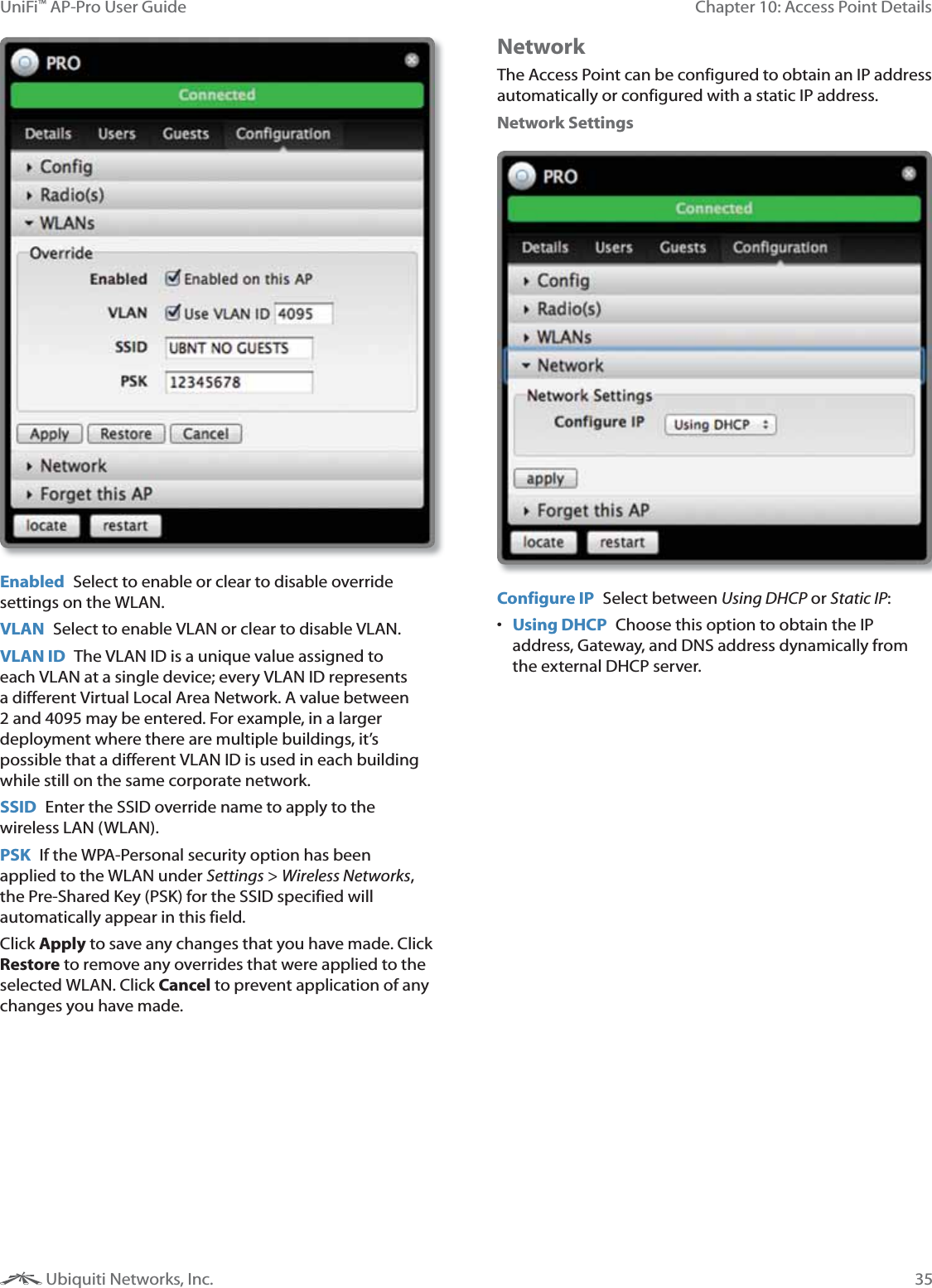
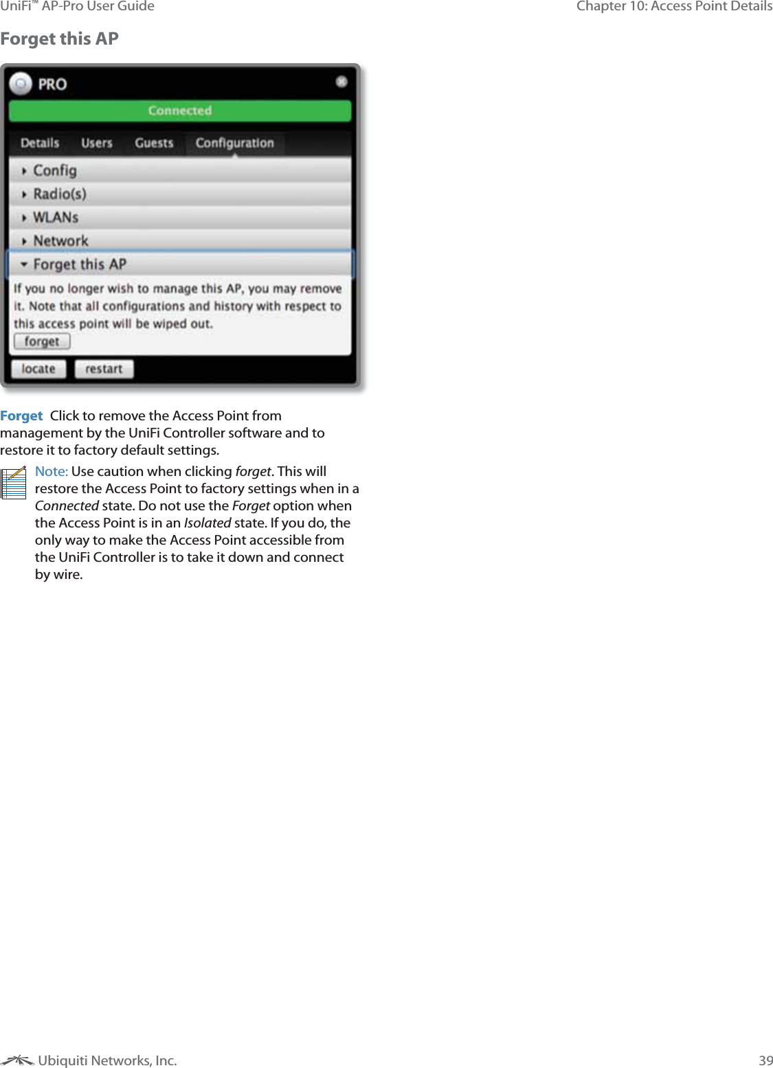
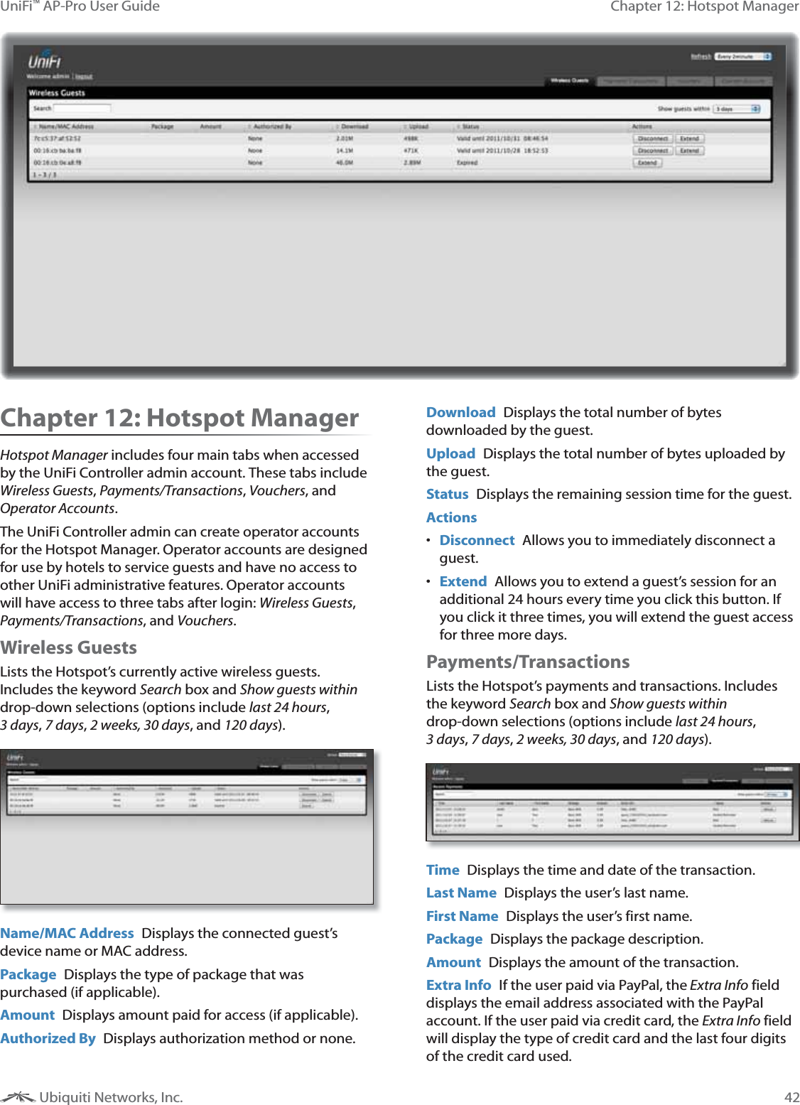
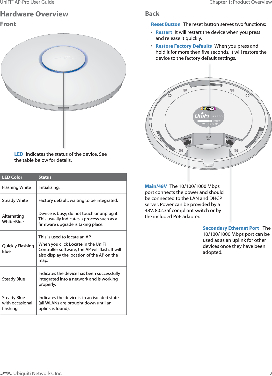
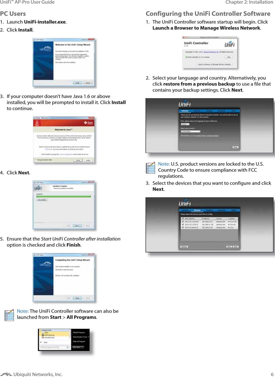
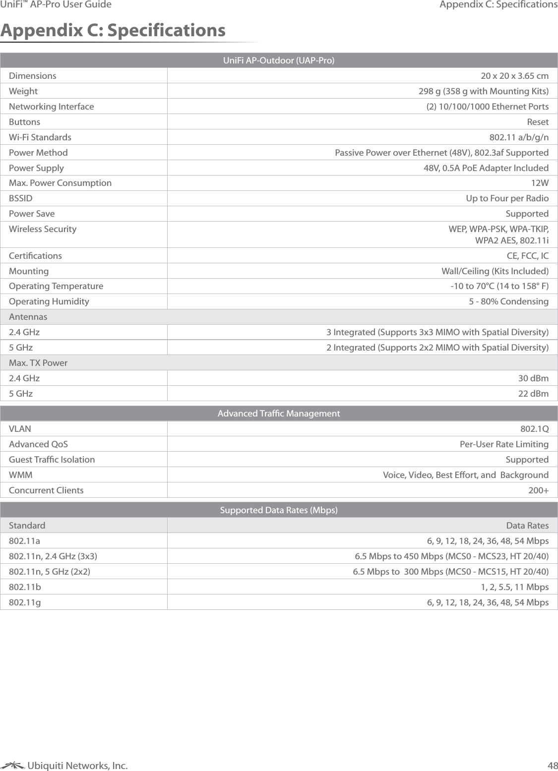
![43Chapter 12: Hotspot ManagerUniFi™ AP-Pro User Guide Ubiquiti Networks, Inc.Status Displays the status of the transaction.Actions Allows you to refund a customer if necessary by clicking the button.VouchersAllows the creation of vouchers including a distributable code, duration values, and use restrictions. Search Enter keywords in the Search box to find a specific voucher based on , Create Time, or Note values. Print all Unused Vouchers Click Print All Unused Vouchers to send a page to your printer with voucher code and validity details.Code Displays a list of active voucher codes.Create Time Displays the time and date the voucher was created.Note Displays any notes that were added using the Notes option during voucher creation.Duration Displays the duration of minutes, hours, or days that the voucher enables the user to access the Internet. Status Indicates whether it is a single-use or multi-use voucher.Actions Revoke Immediately deactivates the selected voucher. Print Batch Prints the selected voucher.Active Voucher Page Slider Adjust the slider from left to right to view all Active Vouchers.Create Vouchers Includes the following: Create __ Specify the number of vouchers to create. __ vouchers Choose whether the voucher can be used One-time or for Multi-use. for __ Choose how long the voucher is valid (options include 8 hours, 24 hours, Y<, J<,\<, Q<or ]). Add Notes Select to add a note specific to the batch of vouchers created. Click Create Vouchers to create the vouchers as specified.Operator Accounts Allows the creation of Operator Accounts that can log in to Hotspot Manager to manage wireless guests, payments/transactions, and vouchers. Search Enter keywords in the Search box to find a specific operator account based on Name, 1, or Notes values. Actions Click Delete to remove an operator. Account Enter a name for the operator. The Account can only be A-Z, a-z, or 0-9. No spaces are allowed. Password Enter a password for the operator. The 1 has to start with A-Z, a-z, or 0-9. The other characters can only be printable ASCII characters. Note If desired, enter a note to identify or describe the operator. Create Operator Click Create Operator to create the operator account as specified. To test the operator account, log out of the UniFi Controller software and log in using the operator credentials. Only the Wireless Guests, Payments/Transactions, and Vouchers tabs will appear.](https://usermanual.wiki/Ubiquiti/UAPRO/User-Guide-1678420-Page-46.png)
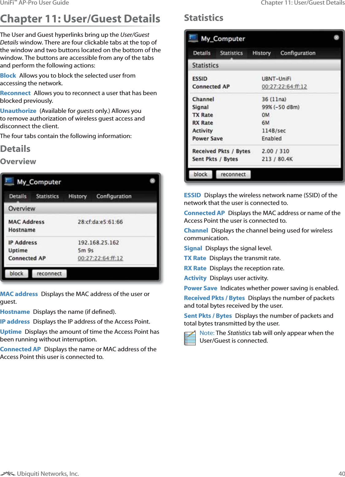
![53Appendix G: Declaration of ConformityUniFi™ AP-Pro User Guide Ubiquiti Networks, Inc.Appendix G: Declaration of ConformityČesky [Czech]UBIQUITI NETWORKS tímto prohla uje, e tento UBIQUITI NETWORKS device, je ve shod se základními po adavky a dal ími p íslu n mi ustanoveními sm rnice 1999/5/ES.Dansk [Danish]Undertegnede UBIQUITI NETWORKS erklærer herved, at følgende udstyr UBIQUITI NETWORKS device, overholder de væsentlige krav og øvrige relevante krav i direktiv 1999/5/EF.Nederlands [Dutch]Hierbij verklaart UBIQUITI NETWORKS dat het toestel UBIQUITI NETWORKS device, in overeenstemming is met de essentiële eisen en de andere relevante bepalingen van richtlijn 1999/5/EG.Bij deze verklaart UBIQUITI NETWORKS dat deze UBIQUITI NETWORKS device, voldoet aan de essentiële eisen en aan de overige relevante bepalingen van Richtlijn 1999/5/EC.EnglishHereby, UBIQUITI NETWORKS, declares that this UBIQUITI NETWORKS device, is in compliance with the essential requirements and other relevant provisions of Directive 1999/5/EC.Eesti [Estonian]Käesolevaga kinnitab UBIQUITI NETWORKS seadme UBIQUITI NETWORKS device, vastavust direktiivi 1999/5/EÜ põhinõuetele ja nimetatud direktiivist tulenevatele teistele asjakohastele sätetele.Suomi [Finnish]UBIQUITI NETWORKS vakuuttaa täten että UBIQUITI NETWORKS device, tyyppinen laite on direktiivin 1999/5/EY oleellisten vaatimusten ja sitä koskevien direktiivin muiden ehtojen mukainen.Français [French]Par la présente UBIQUITI NETWORKS déclare que l’appareil UBIQUITI NETWORKS, device est conforme aux exigences essentielles et aux autres dispositions pertinentes de la directive 1999/5/CE.Par la présente, UBIQUITI NETWORKS déclare que ce UBIQUITI NETWORKS device, est conforme aux exigences essentielles et aux autres dispositions de la directive 1999/5/CE qui lui sont applicables.Deutsch [German]Hiermit erklärt UBIQUITI NETWORKS, dass sich diese UBIQUITI NETWORKS device, in Übereinstimmung mit den grundlegenden Anforderungen und den anderen relevanten Vorschriften der Richtlinie 1999/5/EG befindet”. (BMWi)Hiermit erklärt UBIQUITI NETWORKS die Übereinstimmung des Gerätes UBIQUITI NETWORKS device, mit den grundlegenden Anforderungen und den anderen relevanten Festlegungen der Richtlinie 1999/5/EG. (Wien)Ελληνική [Greek]ΜΕ ΤΗΝ ΠΑΡΟΥΣΑ UBIQUITI NETWORKS ΔΗΛΩΝΕΙ ΟΤΙ UBIQUITI NETWORKS device, ΣΥΜΜΟΡΦΩΝΕΤΑΙ ΠΡΟΣ ΤΙΣ ΟΥΣΙΩΔΕΙΣ ΑΠΑΙΤΗΣΕΙΣ ΚΑΙ ΤΙΣ ΛΟΙΠΕΣ ΣΧΕΤΙΚΕΣ ΔΙΑΤΑΞΕΙΣ ΤΗΣ ΟΔΗΓΙΑΣ 1995/5/ΕΚ. Magyar [Hungarian]Alulírott, UBIQUITI NETWORKS nyilatkozom, hogy a UBIQUITI NETWORKS device, megfelel a vonatkozó alapvetõ követelményeknek és az 1999/5/EC irányelv egyéb elõírásainak.Íslenska [Icelandic]Hér me l sir UBIQUITI NETWORKS yfir ví a UBIQUITI NETWORKS device, er í samræmi vi grunnkröfur og a rar kröfur, sem ger ar eru í tilskipun 1999/5/EC.Italiano [Italian]Con la presente UBIQUITI NETWORKS dichiara che questo UBIQUITI NETWORKS device, è conforme ai requisiti essenziali ed alle altre disposizioni pertinenti stabilite dalla direttiva 1999/5/CE.Latviski [Latvian]Ar o UBIQUITI NETWORKS deklar , ka UBIQUITI NETWORKS device, atbilst Direkt vas 1999/5/EK b tiskaj m pras b m un citiem ar to saist tajiem noteikumiem.Lietuvi [Lithuanian]UBIQUITI NETWORKS deklaruoja, kad šis UBIQUITI NETWORKS įrenginys atitinka esminius reikalavimus ir kitas 1999/5/EB Direktyvos nuostatas.Malti [Maltese]Hawnhekk, UBIQUITI NETWORKS, jiddikjara li dan UBIQUITI NETWORKS device, jikkonforma mal- ti ijiet essenzjali u ma provvedimenti o rajn relevanti li hemm fid-Dirrettiva 1999/5/EC.Norsk [Norwegian]UBIQUITI NETWORKS erklærer herved at utstyret UBIQUITI NETWORKS device, er i samsvar med de grunnleggende krav og øvrige relevante krav i direktiv 1999/5/EF.Slovensky [Slovak]UBIQUITI NETWORKS t mto vyhlasuje, e UBIQUITI NETWORKS device, sp a základné po iadavky a v etky príslu né ustanovenia Smernice 1999/5/ES.Svenska [Swedish]Härmed intygar UBIQUITI NETWORKS att denna UBIQUITI NETWORKS device, står I överensstämmelse med de väsentliga egenskapskrav och övriga relevanta bestämmelser som framgår av direktiv 1999/5/EG.Español [Spanish]Por medio de la presente UBIQUITI NETWORKS declara que el UBIQUITI NETWORKS device, cumple con los requisitos esenciales y cualesquiera otras disposiciones aplicables o exigibles de la Directiva 1999/5/CE.Polski [Polish]Niniejszym, firma UBIQUITI NETWORKS o wiadcza, e produkt serii UBIQUITI NETWORKS device, spełnia zasadnicze wymagania i inne istotne postanowienia Dyrektywy 1999/5/EC.Português [Portuguese]UBIQUITI NETWORKS declara que este UBIQUITI NETWORKS device, está conforme com os requisitos essenciais e outras disposições da Directiva 1999/5/CE.Română [Romanian]Prin prezenta, UBIQUITI NETWORKS declară că acest dispozitiv UBIQUITI NETWORKS este în conformitate cu cerințele esențiale și alte prevederi relevante ale Directivei 1999/5/CE.](https://usermanual.wiki/Ubiquiti/UAPRO/User-Guide-1678420-Page-56.png)