Ubiquiti USL248P UniFi SWITCH User Manual Part 2
Ubiquiti Networks, Inc. UniFi SWITCH Part 2
Ubiquiti >
Contents
- 1. User Manual Part 1
- 2. User Manual Part 2
- 3. User Manual Part 3
User Manual Part 2
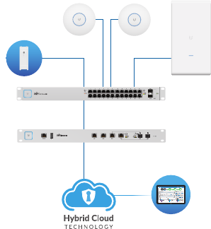
Network Topology Requirements
• A DHCP-enabled network for the UniFi Switch to obtain an
IPaddress (connected devices will also obtain IP addresses
after deployment)
• A UniFi Cloud Key or management station running the UniFi
Controller software v5.4.x or above, located either on-site
and connected to the same Layer2 network, or off-site in a
cloud or NOC
US-L2-24-POE
USG-PRO-4
(DHCP Server)
Internet
UAP-AC-SHD
UAP-AC-M-PRO
UAP-AC-HD
LAN
WAN
UniFi Cloud Key
(UniFi Controller)
Remote Access to
UniFi Controller
Sample Network Diagram
All UniFi devices support off-site management controllers.
For setup details, refer to the User Guide on the website:
documentation.ubnt.com/unifi
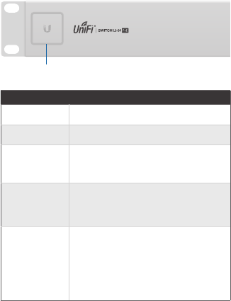
Hardware Overview
Front Panel System LED
System
State Status
Flashing White Initializing.
Steady White Factory defaults, waiting for integration.
Alternating
White/Blue
Device is busy; do not touch or unplug it.
This usually indicates that a process such
as a firmware upgrade is taking place.
Steady Blue
Unit has been adopted and successfully
integrated into a network.
The device is working properly.
Flashing Blue
This is used to locate a device.
When you click Locate in the UniFi
Controller software, the System LED
will flash blue. The software will also
display the location of the UniFi Switch
on themap.
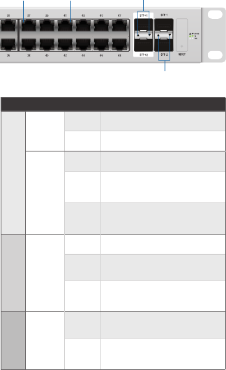
Front Panel Port LEDs
RJ45 PoE RJ45 Speed/Link/Act
SFP Speed/Link/Act
SFP+ Speed/Link/Act
LED State Status
RJ45 Ports
PoE
Off No PoE
Amber IEEE 802.3af/802.3at
Speed/
Link/
Act
Off No Link
Amber Link Established at 10/100Mbps
Flashing Indicates Activity
Green Link Established at 1000Mbps
Flashing Indicates Activity
SFP+ 1-2
(US-L2-48-POE only)
Speed/
Link/
Act
Off No Link
Green Link Established at 1Gbps
Flashing Indicates Activity
White Link Established at 10Gbps
Flashing Indicates Activity
SFP 1-2
Speed/
Link/
Act
Off No Link
Green Link Established at 1Gbps
Flashing Indicates Activity
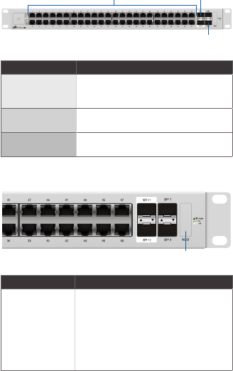
Front Panel Ports
RJ45 1-48
SFP 1-2
SFP+ 1-2
Port Description
RJ45
RJ45 ports support Power over Ethernet
(PoE) and 10/100/1000 Ethernet
connections.
SFP+ 1-2
(US-L2-48-POE only)
Hot-swappable SFP+ ports support
1/10Gbps connections.
SFP 1-2 Hot-swappable SFP ports support 1
Gbps connections.
Front Panel Button
Reset
Button Description
Reset
This button serves two functions for the
UniFi Switch:
• Restart Press and release the Reset
button quickly.
• Restore to Factory Default
Settings Press and hold the Reset
button for more than five seconds.
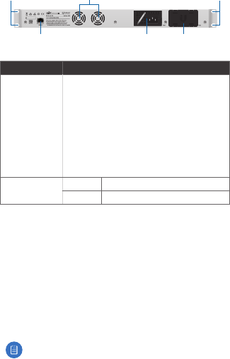
Back Panel
Mounting Holes
PSU
Module
Mounting Holes
Console Slot for
Spare PSU
Fans
Port Description
Console
RJ45 serial console port for Command Line
Interface (CLI) management. Configure the
following settings as needed:
• Baud rate 115200
• Data bits 8
• Parity NONE
• Stop bits 1
• Flow control NONE
PSU Module
LED
Off Inactive, Powered Off
Green Active, Powered On
Installation Requirements
• Phillips screwdriver
• For indoor applications, use Category 5 (or above) UTP
cabling approved for indoor use.
• For outdoor applications, shielded Category 5 (or above)
cabling should be used for all wired Ethernet connections
and should be grounded through the AC ground of the PSU.
We recommend that you protect your networks from
harmful outdoor environments and destructive ESD events
with industrial-grade, shielded Ethernet cable from Ubiquiti
Networks. For more details, visit: www.ubnt.com/toughcable
Note: Although the cabling can be located outdoors,
the UniFi Switch itself should be housed inside a
protective enclosure.
Hardware Installation
WARNING: FAILURE TO PROVIDE PROPER VENTILATION
MAY CAUSE FIRE HAZARD. KEEP AT LEAST 20 MM OF
CLEARANCE NEXT TO THE VENTILATION HOLES FOR
ADEQUATE AIRFLOW.
WARNING: To reduce the risk of fire or electric shock, do
not expose the UniFi Switch to rain or moisture.
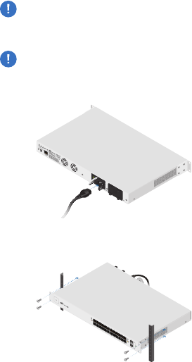
1. Connect the Power Cord to the Power port of the PSU
Module.
2. Attach the UniFi Switch to the rack using the four Mounting
Screws. (If the rack has square slots, then use the Cage Nuts
with the Mounting Screws.)
3. Connect the other end of the Power Cord to a power outlet.
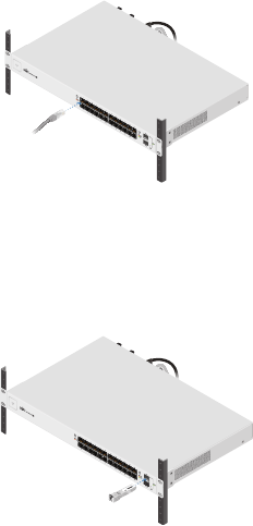
Connecting Ethernet
1. Connect an Ethernet cable from your computer or host
system to any port of the UniFi Switch.
2. Connect Ethernet cables from the Ethernet ports of your
devices to the other numbered ports of the UniFi Switch.
Using SFP Ports
To use an SFP port:
1. Remove the protective plug covering the SFP port.
2. Plug a compatible fiber module into the SFP port.
1000Mbps SM/SC 20KM DDM
Tx1550nm/Rx1310nm
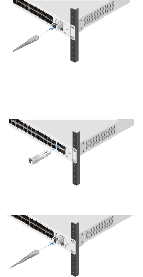
3. Connect a fiber optic cable to the fiber module. Then
connect the other end of the cable to another fiber device.
50
Using SFP+ Ports (US-L2-48-POE only)
To use an SFP+ port:
1. Remove the protective plug covering the SFP+ port.
2. Plug a compatible fiber module into the SFP+ port.
1000Mbps SM/SC 20KM DDM
Tx1550nm/Rx1310nm
3. Connect a fiber optic cable to the fiber module. Then
connect the other end of the cable to another fiber device.
50