Ubisense America MOD23 Location tracking tag User Manual Modular Ubitag v2 3
Ubisense Limited Location tracking tag Modular Ubitag v2 3
User Manual
Copyright © 2009 Ubisense Limited, All Rights Reserved
Wideband Location System
Modular Ubitag V2.3
User’s Manual
Written By
Andy Ward
Ubisense Limited
St Andrew’s House
St Andrew’s Road
Chesterton
Cambridge
CB4 1DL
ENGLAND
Tel: +44 (0)1223 535 170
Fax: +44 (0)1223 535 167
Email: support@ubisense.net
WWW: http://www.ubisense.net/
Released: October 2009
Copyright © 2009 Ubisense Limited, All Rights Reserved
Table of Contents
Introduction...................................................................................................................................... 1
Regulatory Information for the United States of America................................................................ 1
Modular Ubitag V2.3 Specifications................................................................................................. 2
Integration information..................................................................................................................... 3
1
Ubisense –Wideband Location System – Modular Ubitag V2.3
Introduction
The Modular Ubitag V2.3 is a wireless module intended to be integrated into other devices for the
real-time location of objects. It transmits wideband pulses which are picked up by a network of
basestations (Ubisensors), allowing the 3D position of the tag to be found. The use of wideband
technology enables greater positioning accuracy within buildings than other wireless
technologies, because it is much less susceptible to multipath interference effects. Applications of
the system include healthcare, workplace productivity, security, retail management and
manufacturing.
This document describes the features and specifications of the Modular Ubitag and important
regulatory information concerning its use and integration into other devices.
Regulatory Information for the United States of America
The Modular Ubitag V2.3 is approved Parts 15.249 and 15.250 of the FCC rules as a Modular
Transmitter.
The product into which the Modular Ubitag V2.3 is incorporated must bear a label per the FCC
requirements which shows the FCC ID assigned to the Modular Ubitag V2.3 as follows.
Contains FCC ID: SEAMOD23
The following information must be conveyed in the information supplied to the End User of the
product into which the Modular Ubitag V2.3 is incorporated:
This device complies with Part 15 of the FCC Rules. Operation is subject to the following two
conditions: (1) this device may not cause harmful interference, and (2) this device must
accept any interference received, including interference that may cause undesired operation.
The user’s manual or instruction manual shall caution the user that changes or modifications to
the equipment not expressly approved by the party responsible for the grant of equipment
authorization issued by the FCC could void the user’s authority to operate the equipment under
the grant of equipment authorization, for example:
CAUTION: Any changes or modifications made to the Modular Ubitag V2.3 which are not
expressly approved by the Ubisense Limited could void the user's authority to operate the
equipment.

2
Ubisense –Wideband Location System – Modular Ubitag V2.3
Modular Ubitag V2.3 Specifications
Wideband transmitter section
Operates under: FCC Part 15.250
Centre frequency: 6.545GHz
-10dB bandwidth: 0.963GHz
Conventional 2.4GHz radio transceiver
Operates under: FCC Part 15.249
Lowest channel frequency: 2402.5MHz
Highest channel frequency: 2480.5MHz
General specifications
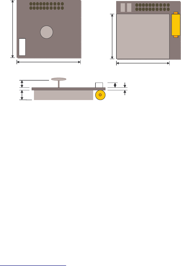
Dimensions (WxHxD): 24.5mm x 24.5mm x 9mm
Weight: 6g
Power supply: 2.3V-5.25V DC supply
Operating temperature range: -40ºC to +85ºC
3
Ubisense –Wideband Location System – Modular Ubitag V2.3
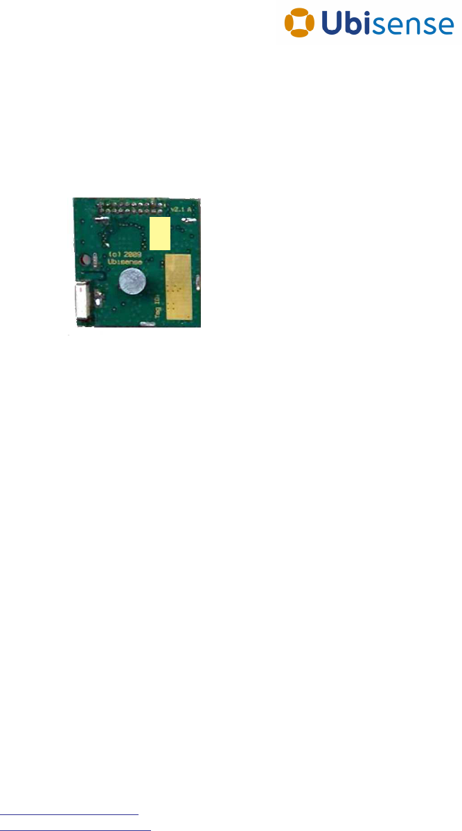
Integration information
The dimensions of the module PCB are shown below:
When mounting the tag on another device care must be taken to avoid occlusion of the antennas
by tall components, shielding, or mounting screws. There should be an air gap of at least 1mm
left around both of the antennas to avoid detuning.
While the connector provides some mechanical fixing it is not recommended that this is the only
fixing point. A double-sided pad has been supplied that can be fitted to the top of the screening
can to securely fix the module to a PCB.
When designing the PCB it is recommended that there is no ground plane underneath the
module.
Power should be supplied on the following pins of the header:
2.3V-5.25V DC power input: Pin 3
Ground: Pins 5,6,9,10,14,18,19
A number of pins on the module’s header may be used for digital input/output and analogue input.
Note that application-specific use of these pins will require Ubisense to write modified firmware
for the device, and therefore integrators wishing to make use of these features should contact
Ubisense in the first instance.
The header used on the module is a Major League TSHS-5 10-D-04-A-F-LF, a standard 1.27mm
pitch through-hole pin header. The recommended connector to use with the module is:
Connector: Major League LSSHS-5 10-D-06-F-TB-P-LF (SMD)
Please refer to http://www.mlelectronics.com for further information and ordering details.
4.5mm
3mm
2.1mm
1.6mm
4.5mm
3mm
2.1mm
1.6mm
24.5mm
24.5mm
24.5mm
24.5mm
20mm
20mm
Ubisense
20mm
20mm
Ubisense