Ubisense America UBISENSOR10 Ubitag V1.0 User Manual Ubisensor v1 0
Ubisense Limited Ubitag V1.0 Ubisensor v1 0
users manual

!" #$ #%&#'( ) ( *
+, -./!0&!1
23, -./!0&!41
' , 5 6
, ,778 8 8 667
,
Table of Contents
Introduction.............................................................................................................................................1
Information to the User ..........................................................................................................................1
Features of the Ubisensor .....................................................................................................................2
Installation and Operation Instructions .................................................................................................3
Mounting options ............................................................................................................................3
Setting up a sensor cell..................................................................................................................3
Switching the Ubisensor on ...........................................................................................................4
Tuning the radio power output.......................................................................................................5
Troubleshooting..............................................................................................................................8
Ubisensor Specifications .......................................................................................................................9

Ubisense – Ultra-wideband In-Building Location System – Ubisensor V1.0
Introduction
The Ubisensor V1.0 is a basestation used by the Ubisense In-Building Location System, which
supports the real-time location of objects within buildings. It detects ultra-wideband (UWB) pulses
emitted by wireless tags (Ubitags) located inside the building, allowing the 3D position of the tag
to be found. The use of UWB technology enables greater positioning accuracy within buildings
than other wireless technologies, because it is much less susceptible to multipath interference
effects. Applications of the system include healthcare, workplace productivity, security, retail
management and manufacturing.
This document describes the features and specifications of the Ubisensor, important regulatory
information concerning its use, and details on how to diagnose potential problems.
Information to the User
CAUTION: The Ubisensor system must be professionally installed in accordance with these
instructions. Improper installation may violate 47 U.S.C. 301 and could subject the operator to
serious penalties
The Ubisensor V1.0 contains a wireless transceiver certified under FCC Part 15.249.
This device complies with Part 15 of the FCC Rules. Operation is subject to the following two
conditions: (1) this device may not cause harmful interference, and (2) this device must accept
any interference received, including interference that may cause undesired operation.
NOTE: This equipment has been tested and found to comply with the limits for a Class A digital
device, pursuant to Part 15 of the FCC Rules. These limits are designed to provide reasonable
protection against harmful interference when the equipment is operated in a commercial
environment. This equipment generates, uses, and can radiate radio frequency energy
and, if not installed and used in accordance with the instruction manual, may cause harmful
interference to radio communications. Operation of this equipment in a residential area is likely to
cause harmful interference in which case the user will be required to correct the interference at
his own expense.
CAUTION: Any changes or modifications made to the Ubisensor which are not expressly
approved by Ubisense Limited could void the user's authority to operate the equipment.
Ubisense – Ultra-wideband In-Building Location System – Ubisensor V1.0
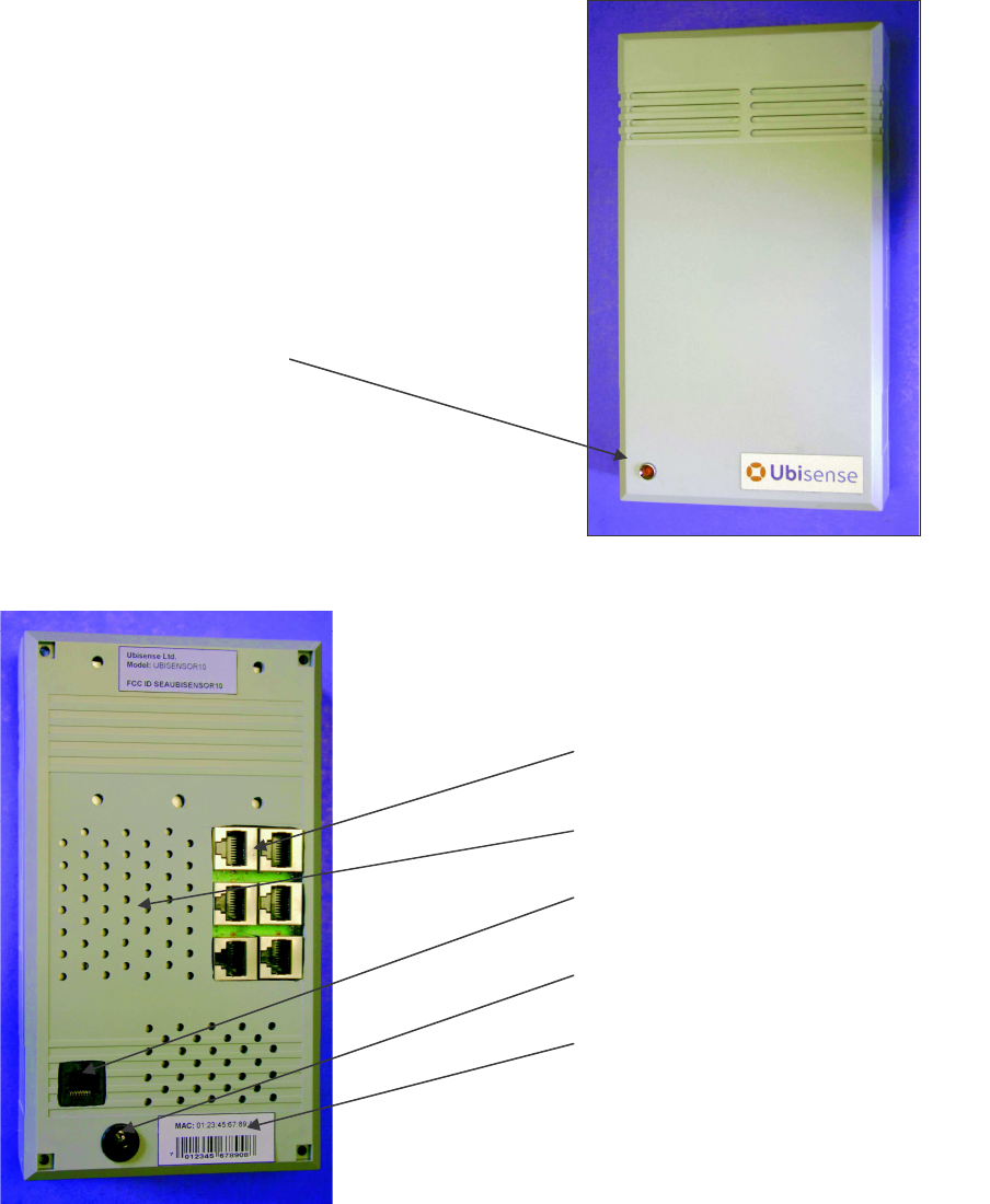
Features of the Ubisensor
The diagrams below show several important features of the Ubisensor:
Status LED
Timing cable sockets
Ventilation holes
Networking socket
Power supply socket
MAC address (ID) label
Ubisense – Ultra-wideband In-Building Location System – Ubisensor V1.0
Installation and Operation Instructions
Mounting options
Ubisensors have five holes drilled in the back of the case, to which external clamps and brackets
can be attached. Four of the holes are M4 size, the other hole is M6 size (and can be used in
conjunction with a standard photographic camera mount).
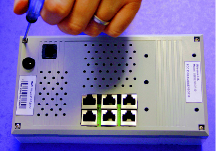
To attach a clamp, bracket or mounting plate to the back of the Ubisensor, it will be necessary to
remove the rear of the device by undoing the four retaining screws (as shown in the photograph
below). Take care removing the back of the device – the DC power supply socket is attached to it.
Once the mounting device is attached to the back of the Ubisensor (normally either by passing
bolts from the inside of the case to captive nuts outside, or by screwing nuts inside the case onto
a bolt attached to the clamp outside), the rear of the device can be replaced and secured using
the four screws removed earlier.
When the Ubisensor is mounted in its final position, make sure the ventilation holes on the top,
bottom and rear of the device are not obstructed.
Setting up a sensor cell
Ubisense will have supplied you with an updated location system database containing
configuration information for the equipment you have received. At this point, it’s worth checking
that the MAC (Media Access Control) addresses of the Ubisensors you have received match the
information in the database, using the Ubisense location system configuration tools. See the
software manual for details on how to examine the contents of the configuration database – the
MAC address for each Ubisensor is printed on a label affixed to the rear of the unit (see “Features
of the Ubisensor”).
Once you are sure you have the correct equipment to hand, the sensor cells for the system can
be set up. In the Ubisense location system, a large area of space is covered by a number of
sensor cells, each of which (individually) covers a smaller area.
Each sensor cell has a master unit and number of slave units (usually three or more). The
information provided by the Ubisense location system configuration tools will let you identify, for
any particular sensor cell, which unit is the master and which are slaves, using the MAC
addresses of the devices. The master unit in each sensor cell generates a timing signal which is
used by the slave units of that cell. The master unit is connected to the slave units using shielded
Ubisense – Ultra-wideband In-Building Location System – Ubisensor V1.0
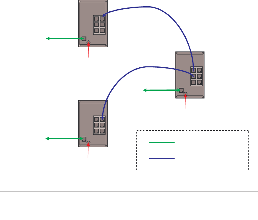
Category 5e cable (or better). A timing cable from the master to a slave can be plugged into any
free timing socket on the master, but must be plugged into the top right-hand timing socket on the
slave, as shown in the diagram below.
All sensors are connected to the standard building network using a Category 5 unshielded cable
(or better), and to a power supply (typically via a 12V DC adaptor such as the Stontronics EPA-
121DA-12). The final wiring interconnection diagram for a three-member sensor cell would be as
follows:
WARNING: Never plug a networking cable into a timing cable socket, or a timing cable into the
networking socket!
Switching on the Ubisensor
To turn on a Ubisensor, simply turn on the power to the device. The LED on the front of the
Ubisensor should illuminate, and the device will begin to attempt to contact the Ubisense location
system (which should already have been installed on your network – see the software manual for
details). Configuration of the Ubisensor is entirely automatic, and is under the control of the
Ubisense location system.
12V DC
12V DC
12V DC
MASTER
UNIT
SLAVE
UNIT
SLAVE
UNIT
To
network
To
network
To
network
Cat. 5 unshielded (or better)
Cat. 5e shielded (or better)
Ubisense – Ultra-wideband In-Building Location System – Ubisensor V1.0
Calibrating the Ubisensor
When the Ubisensor has been installed in its final location, its position and orientation must be
found and entered into the Ubisense location system’s database. The Ubisense location system
management tools make this calibration process simple and quick – refer to the software manual
for details.
Tuning the Ubisensor radio output power
The master Ubisensor in each sensor cell transmits conventional radio messages to coordinate
the activity of Ubitags in its vicinity. Once you have configured and switched on the Ubisensors in
a sensor cell, the output power of the master Ubisensor’s radio signals must be adjusted. This
step must be performed by qualified professionals who have access to the Ubisense location
system management tools.
Reception of conventional radio signals from the Ubisensor network enables the UWB
functionality in Ubitags, which in turn allows Ubisensors to find the location of those Ubitags.
Ubitags are certified under FCC Part 15.517 (“Indoor UWB devices”) and their use is subject to
technical requirements for indoor UWB systems, in particular the stipulation that the devices must
only be used indoors. By correctly adjusting the radio output power of the master Ubisensor in
each sensor cell, the installed Ubisensor network will cover only the area inside the building,
preventing Ubitags from emitting UWB signals outdoors.
The default power setting stored in the Ubisense location system’s database for each Ubisensor
is zero, so the following steps must be followed to correctly adjust the radio output power of the
master Ubisensors:
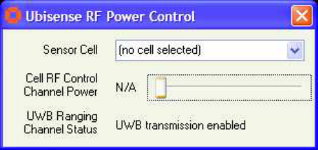
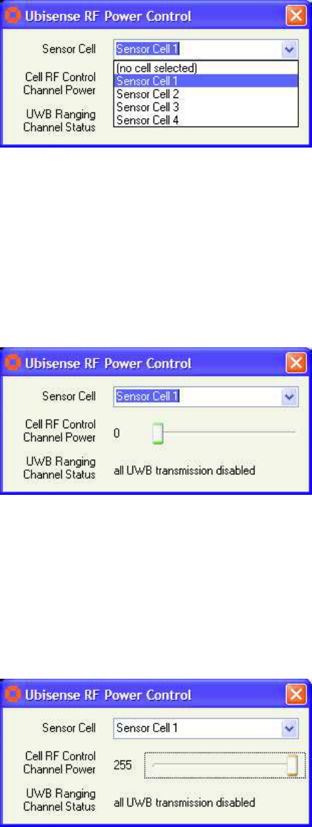
1. Run the Ubisense RF Power Control application from the directory in which the Ubisense
location system management tools have been installed. The following dialog box should
be shown:
2. The drop-down Sensor Cell list shows the sensor cells that have been pre-configured by
Ubisense for your installation. Choose one of the cells.
Ubisense – Ultra-wideband In-Building Location System – Ubisensor V1.0
When a sensor cell is selected, the Ubisense location system automatically turns off radio
transmissions from the master Ubisensors of other sensor cells. By doing this, it is
possible to tune the output power from the selected sensor cell’s master Ubisensor in
isolation.
3. The dialog box should now show the current radio output power for the selected sensor
cell’s master Ubisensor, as shown below. The output power can range from 0 (zero
output power) to 255 (maximum output power), and can be changed by moving the slider
from left to right.
The dialog box also shows the message “all UWB transmission disabled”. This message
indicates that the radio signals sent out by the master Ubisensor contain information
preventing a Ubitag that receives them from emitting UWB signals. This allows the extent
of the master Ubisensor’s coverage to be tuned without the risk that Ubitags outside the
building might be triggered accidentally into emitting UWB signals.
4. Set the output power for the master Ubisensor by adjusting the slider. Start the tuning
process by adjusting the master Ubisensor’s output power to maximum.
Ubisense – Ultra-wideband In-Building Location System – Ubisensor V1.0
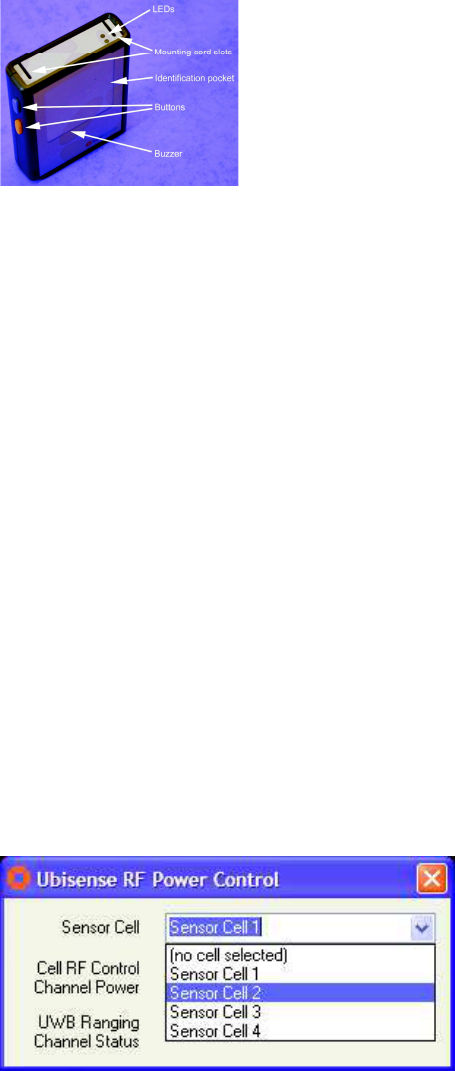
5. Select a Ubitag and place it near the master Ubisensor. The Ubitag has two LEDs
(whose positions are indicated on the diagram below)
If the green LED flashes on the Ubitag, it is receiving radio messages from the master
Ubisensor, and would (in normal operation) transmit UWB signals at that point in space.
If the red LED flashes on the Ubitag, it is searching for radio messages from the master
Ubisensor, and would not transmit UWB signals at that point in space.
The aim of the tuning procedure is to adjust the radio output power such that the green
LED flashes on the Ubitag at points within the building which are covered by the master
Ubisensor, but that only the red LED flashes on the Ubitag when it is placed outside the
building.
Test the coverage of the system by walking around the outside perimeter of your
building. If the green LED illuminates outside the building, the master Ubisensor’s
output power is too high. Reduce the radio output power for the sensor cell using
the slider bar, and repeat stages 4 and 5.
6. Once you have determined that the master Ubisensor’s output power is such that Ubitags
outside the building will not be triggered, test coverage of the sensor cell by walking
around the inside perimeter of the building. If there are large gaps in the coverage within
the building (indicated by illumination of the red LED on the Ubitag) your sensor cells may
need re-planning, and you should contact Ubisense.
7. When you are happy with the coverage of the sensor cell, select another sensor cell and
repeat stages 4-6.
Ubisense – Ultra-wideband In-Building Location System – Ubisensor V1.0
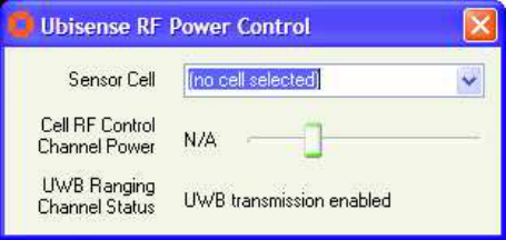
8. Finally, when all sensor cells have been tuned, select the option “(no cell selected)” from
the drop-down menu. This will re-enable the radio output of all master Ubisensors (and
will set their output powers at the tuned values), and will re-enable transmission of UWB
signals from Ubitags.
By following these instructions, all sensor cells in the system will have been tuned so that their
radio signals cannot be picked up by Ubitags outside the building, and so Ubitags will only
transmit ultra-wideband signals indoors, in accordance with FCC Part 15.517.
Troubleshooting
If you believe that a Ubisensor is not functioning correctly, and the Ubisense location system
management tools are not able to diagnose the problem, it is likely that the Ubisensor is not
communicating with the rest of the location system for some reason. Check the following:
• The Ubisensor is connected to a power supply, and the supply is switched on.
• The networking cable is fully plugged in at both ends.
• Your local network port is connected to the rest of your network.
• The link light corresponding to the Ubisensor network connection is illuminated on the
nearest upstream switch.
If you are still unable to determine the cause of the problem, contact your system installer or
Ubisense.

Ubisense – Ultra-wideband In-Building Location System – Ubisensor V1.0
Ubisensor Specifications
Conventional radio transceiver section (FCC ID: SEAUBISENSOR10)
Number of channels: 7
Lowest channel frequency: 908.36MHz
Highest channel frequency: 915.00MHz
Maximum output power: -7dBm
General specifications
Dimensions: 200mm x 112mm x 70mm
Power supply: 12V DC, centre-pin positive
Operating temperature range: -20ºC to +60ºC