Ubisense America UBITAG10-U Ubitag V1.0 User Manual Ubitag v1 0
Ubisense Limited Ubitag V1.0 Ubitag v1 0
users manual

!
"# $% $&' $() * ) +
,- ./0"1'"2
34- ./0"1'"52
( - 6 7
- -889 9 9 778
-
Table of Contents
Introduction ...................................................................................................................................... 1
Information to the User .................................................................................................................... 1
Features of the Ubitag ..................................................................................................................... 2
Installation and Operation Instructions ............................................................................................ 3
Switching the Ubitag on for the first time.................................................................................. 3
Replacing the batteries in the Ubitag ....................................................................................... 4
Using the mounting cord option................................................................................................ 5
Troubleshooting........................................................................................................................ 6
Ubitag Specifications ....................................................................................................................... 7
Requirements for indoor UWB device operation ............................................................................. 7
Ubisense – Ultra-wideband In-Building Location System – Ubitag V1.0
Introduction
The Ubitag V1.0 is a wireless device intended to be used for the real-time location of objects
within buildings. It transmits ultra-wideband (UWB) pulses which are picked up by a network of
basestations (Ubisensors) placed inside the building, allowing the 3D position of the tag to be
found. The use of UWB technology enables greater positioning accuracy within buildings than
other wireless technologies, because it is much less susceptible to multipath interference effects.
Applications of the system include healthcare, workplace productivity, security, retail
management and manufacturing.
This document describes the features and specifications of the Ubitag, important regulatory
information concerning its use, and details on how to diagnose potential problems.
Information to the User
The Ubitag V1.0 is an ultra-wideband (UWB) wireless device certified under FCC Part 15.517. Its
use is subject to technical requirements for indoor UWB systems, in particular the stipulation that
the devices must only be used indoors. Users should note carefully the following information:
• CAUTION: This equipment may only be operated indoors. Operation outdoors is in
violation of 47 U.S.C. 301 and could subject the operator to serious penalties.
• Ubitags will only operate (i.e. transmit UWB signals) in conjunction with an in-building
Ubisensor network, which must be professionally installed. The installed Ubisensor
network will be configured to cover only the area inside the building, preventing Ubitags
from emitting UWB signals outdoors. Contact your system administrator if you are unsure
as to the extent of coverage of the Ubisense In-Building Location System in your building.
• This device complies with Part 15 of the FCC Rules. Operation is subject to the following
two conditions: (1) this device may not cause harmful interference, and (2) this device
must accept any interference received, including interference that may cause undesired
operation.
Users should also carefully note the following information:
• CAUTION: Any changes or modifications made to the Ubitag which are not expressly
approved by the Ubisense Limited could void the user's authority to operate the
equipment.
• NOTE: This equipment has been tested and found to comply with the limits for a Class B
digital device, pursuant to Part 15 of the FCC Rules. These limits are designed to provide
reasonable protection against harmful interference in a residential installation. This
equipment generates, uses and can radiate radio frequency energy and, if not installed
and used in accordance with the instructions, may cause harmful interference to radio
communications. However, there is no guarantee that interference will not occur in a
particular installation. If this equipment does cause harmful interference to radio or
television reception, which can be determined by turning the equipment off and on, the
user is encouraged to try to correct the interference by one or more of the following
measures:
-- Reorient or relocate the receiving antenna.
-- Increase the separation between the equipment and receiver.
-- Connect the equipment into an outlet on a circuit different from that to which
the receiver is connected.
-- Consult the dealer or an experienced radio/TV technician for help.
Ubisense – Ultra-wideband In-Building Location System – Ubitag V1.0
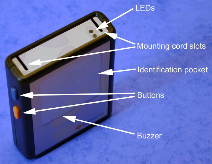
Features of the Ubitag
The diagram below shows several important features of the Ubitag:
Ubisense – Ultra-wideband In-Building Location System – Ubitag V1.0
Installation and Operation Instructions
Switching the Ubitag on for the first time
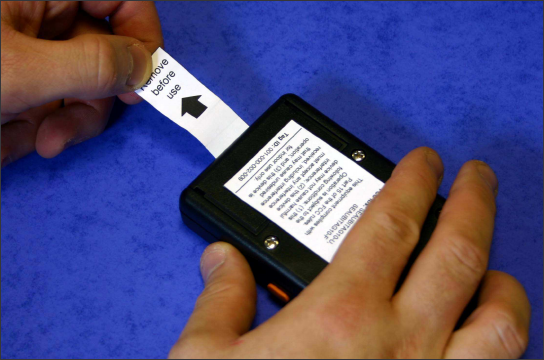
The Ubitag is supplied with batteries. A paper tab prevents the device from operating and drawing
current from the batteries until it is removed by the user. The Ubitag can be switched on for the
first time by pulling the paper tab directly away from the body of the Ubitag and clear of the
device, as shown in the photograph below. The Ubitag will bleep once and flash its LEDs to
indicate correct start-up, and the Ubisense In-Building Location System will then be able to
determine the Ubitag’s location.
Ubisense – Ultra-wideband In-Building Location System – Ubitag V1.0
Replacing the batteries in the Ubitag
The Ubitag uses two Sony CR2450 3V lithium coin cells (or equivalent). Ubitags frequently report
their battery health to the system via the Ubisensors, so system administrators should be notified
by the system when the batteries in a particular tag require replacement.
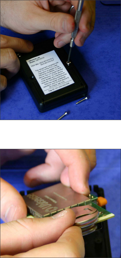
To replace the batteries in a Ubitag, remove the back panel of the device by unscrewing the four
retaining screws as shown in the photograph below:
Next, remove the two spent batteries from the retainers:
Ubisense – Ultra-wideband In-Building Location System – Ubitag V1.0
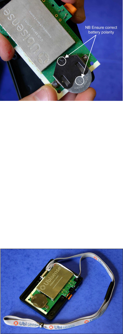
Leave the Ubitag unpowered for 30 seconds, then insert two fresh batteries into the retainers,
observing the polarity marked on the battery and the retainers:
When both batteries have been replaced, the Ubitag will bleep once and flash its LEDs to indicate
correct start-up, and the Ubisense In-Building Location System will then be able to determine the
Ubitag’s location. Replace the back of the Ubitag and tighten the four screws removed previously
to complete reassembly of the device.
Should the Ubitag not bleep and flash its LEDs to indicate correct start-up after the batteries have
been replaced, remove the batteries, check that they are fresh, wait for 30 seconds, and reinsert
the batteries. Contact your system administrator if you continue to have problems replacing the
batteries in the Ubitag.
Using the mounting cord option
In some applications it may be advantageous to mount the Ubitag using a cord. The top panel of
the Ubitag case has two slots to facilitate the use of a mounting cord. To insert the cord, remove
the back panel of the Ubitag by undoing the retaining screws (as shown above in the section
‘Replacing the batteries in the Ubitag’) and insert the mounting cord as shown in the photograph
below. Replace the back of the Ubitag and tighten the four screws removed previously to
complete reassembly of the device.
To remove the mounting cord, undo the retaining screws on the back panel of the Ubitag (as
shown above in the section ‘Replacing the batteries in the Ubitag’), remove the panel, and detach
the mounting cord. Replace the back of the Ubitag and tighten the four screws removed
previously to complete reassembly of the device.
Ubisense – Ultra-wideband In-Building Location System – Ubitag V1.0
Troubleshooting
The activity of the LEDs on the Ubitag may be used to diagnose potential problems with the
device:
• Periodic, short (less than 1/10
th
second) flashes of the green LED indicate that the tag is
in communication with the local Ubisensor network, and that the device is emitting ultra-
wideband signals enabling its position to be found.
• Longer (half-second) flashes of the red LED indicate that the tag is searching for signals
from the local Ubisensor network, and that tracking functionality is not available at that
location. Ensure that the tag is within an area of the building covered by the Ubisense In-
Building Location System.
If you are still unsure as to whether or not the Ubitag is operating correctly, contact your system
administrator, who should be able to use Ubisense’s monitoring tools to determine the extent and
cause of any potential problem.

Ubisense – Ultra-wideband In-Building Location System – Ubitag V1.0
Ubitag Specifications
UWB transmitter section (FCC ID: SEAUBITAG10-U)
Centre frequency: 5.963GHz
-10dB bandwidth: 2.025GHz
Output power: -42.5dBm/MHz
Conventional radio transceiver section (FCC ID: SEAUBITAG10-F)
Number of channels: 7
Lowest channel frequency: 908.36MHz
Highest channel frequency: 915.00MHz
Output power: -7dBm
General specifications
Dimensions: 91mm x 66mm x 21mm
Update rate: Variable (10Hz to 0.0375Hz)
Power supply: 2 x Sony CR2450 3V lithium coin cells (or equivalent)
Operating temperature range: -20ºC to +60ºC
Requirements for indoor UWB device operation
This section lists the technical requirements laid down in the FCC’s rules which must be met by
UWB devices operating indoors under §15.517 of those rules. Ubitags operating with a correctly-
installed Ubisense location system will meet these requirements.
(1) Indoor UWB devices, by the nature of their design, must be capable of operation only indoors.
The necessity to operate with a fixed indoor infrastructure, e.g., a transmitter that must be
connected to the AC power lines, may be considered sufficient to demonstrate this.
(2) The emissions from equipment operated under this section shall not be intentionally directed
outside of the building in which the equipment is located, such as through a window or a doorway,
to perform an outside function, such as the detection of persons about to enter a building.
(3) The use of outdoor mounted antennas, e.g., antennas mounted on the outside of a building or
on a telephone pole, or any other outdoors infrastructure is prohibited.
(4) Field disturbance sensors installed inside of metal or underground storage tanks are
considered to operate indoors provided the emissions are directed towards the ground.
(5) A communications system shall transmit only when the intentional radiator is sending
information to an associated receiver.