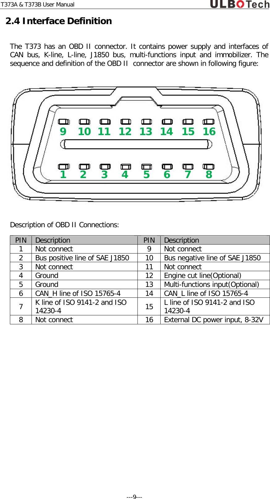
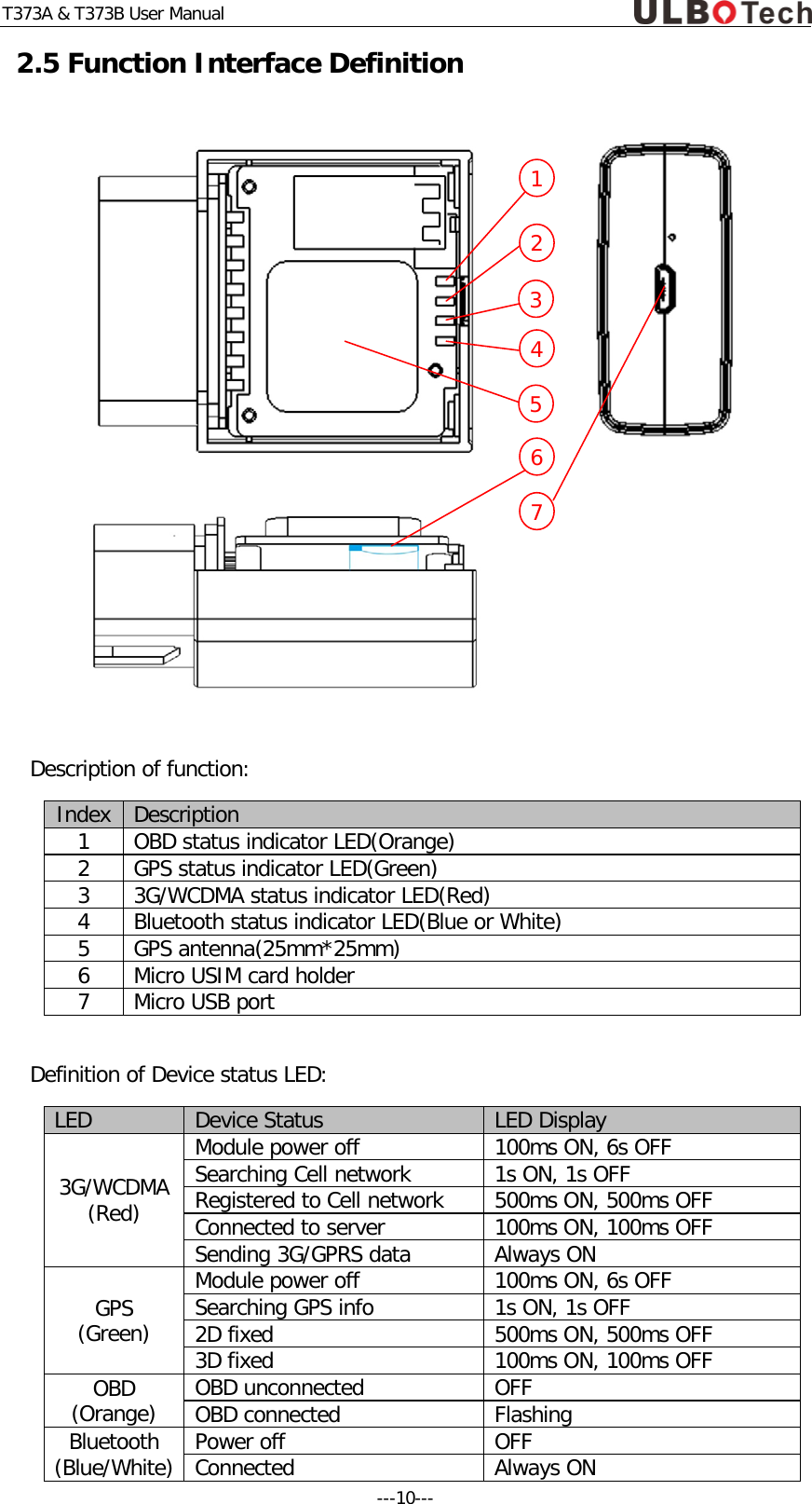
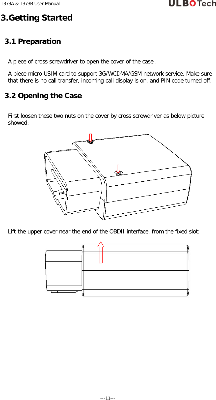
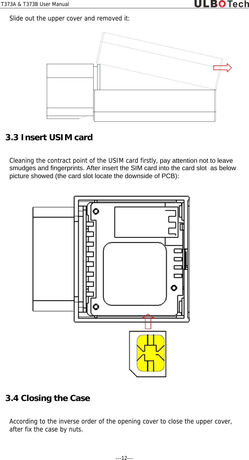
Ulbo Tech T373B OBDII GPS Tracker User Manual

Ulbo Tech Co., Limited OBDII GPS Tracker

User Manual

    3G WCDMA Bluetooth OBD GPS Tracker T373A & T373B User Manual    CE 2200   http://www.ulbotech.com mkt@ulbotech.com
T373A & T373B User Manual Attention! 1. Do not disassemble the device. When the device fails, shall the manufacture or the authorized specialist repair,   self disassemble the device maintenance will be lost.   2. The device must be installed by the specialist, otherwise may affect the using effect. 3. The device is susceptible to water and humidity, need to install and use in a dry environment. 4. The device belonging to the wireless communication equipment, generates ,uses and radiate radio frequency energy, may cause interference to the nearby equipments. 5. The device cannot be disposed with other household waste when it reaches end of using life. To avoid  harmful the environment or human health caused by failing to properly control the waste, please separately process this device with other waste and recycling properly, to promote resource recycling.    ---2---
T373A & T373B User Manual Document Title T373A & T373B User Manual Version 1.003 Date 2015-06-20 Status Release        General Notes Ulbotech offers this information as a service to its customers, to support application and engineering efforts that use the products designed by Ulbotech. The information provided is based upon requirements specifically provided to Ulbotech  by the customers.  Ulbotech  has not undertaken any independent search for additional relevant information, including any information that may be in the customer’s possession. Furthermore, system validation of this product designed by Ulbotech within a larger electronic system remains the responsibility of the customer or the customer’s system integrator. All specifications supplied herein are subject to change.    Copyright  This document contains proprietary technical information which is the property of Ulbotech  copying of this document and giving it to others and the using or communication of the contents thereof, are forbidden without express authority. Offenders are liable to the payment of damages. All rights reserved in the event of grant of a patent or the registration of a utility model or design. All specification supplied herein are subject to change without notice at any time.    Copyright © Ulbotech 2015 ---3---
T373A & T373B User Manual Contents 0.Revision History ........................................................................................... 5 1.Introduction ................................................................................................ 6 2.Product Overview ........................................................................................ 7 3.Getting Started .......................................................................................... 11 4.Installation USB Driver ............................................................................... 13 5.Initiation Device ........................................................................................ 13 6.Connect with Immobilizer and Input ............................................................ 23 7.Installation Device ..................................................................................... 24 8.Common Problems ..................................................................................... 25     ---4---
T373A & T373B User Manual 0.Revision History Revision     Date Author Description of change 1.000 2014-10-05 David Lin Initial 1.001 2014-10-20 David Lin Add SAE J1939 function 1.002 2015-04-12 David Lin Add multi-function input 1.003 2015-06-20 David Lin      ---5---
T373A & T373B User Manual  1.Introduction Ulbotech's T373 A&B  are the latest OBDII GPS Tracker supporting 3G WCDMA and Bluetooth 4.0 low energy, it's built-in Telit xE910 family cell module which provided by the most professional M2M wireless solutions product service in the world -Telit, which can support from 2G to 4G including GSM/WCDMA/CDMA global network coverage, there's not regional restrictions for product application.  The T373 A&B also with internal u-blox MAX-7 GNSS module to support GPS and GLONASS, with the 25mm*25mm high gain active antenna and the Assist Now AGPS function to ensure the device can fast time positioning even so the T373 A&B is installed in the most hidden place of the vehicle.  It's built-in On-board Diagnostics(OBD II)/SAE J1939 function can obtain the on-board data such as RPM, SPD, ECT, Fuel level and Fuel consumption etc from the vehicle in real-time. It's in-time monitoring of Diagnostic Trouble Code(DTC), OBDII parameter and alarm. It's equipped with 3D acceleration enable to set in real-time detection of  the motion and the 8 type of driving behavior, able to make an effective analysis for the bad driving behavior of the driver and the fuel consumption, including to provide the improvement suggestions.  It's Bluetooth 4.0 energy enable easily connected various compatible Bluetooth mobile devices to achieve extended functionality, like as iOS, Android... The T373 A&B is used a wide variety of Fleet Management, Insurance & rental, Roadside Assistance, Driver Behavior Monitoring, Safety & Security etc. 1.1 Reference document Index Document Name 1 Ulbotech Tracking Device Communication Protocol 2 Tracking Device VCP driver installation user manual 3 Tracking Device Configuration Software manual 4 Tracking Device File Import & Export Software manual 5 Ulbotech OBDII Extended cable connection chart  ---6---
T373A & T373B User Manual 2.Product Overview 2.1 Description T373A & T373B is based on the OBD II interface GPS vehicle tracking device, compact design and easy to install. T373A & T373B contains an OBD II connector which complies with J1962 standard. It comprises a micro USB connector, a built-in  3G/WCDMA/GSM antenna, an internal Bluetooth antenna,  an internal GPS antenna, a multi-functions input, an immobilizer output and 4pcs LEDs .    2.2 Features  OBD connectivity, simple to install, easy to use.  Supports all OBDII protocols and SAE J1939(250/500kbaud).  Internal Telit xE910 family modem, supports 2G/3G/4G network.  U-blox MAX-7 GPS module with A-GPS.  Internal Bluetooth, GSM/WCDMA and 25mm*25mm active GPS antenna.   Internal  Bluetooth 4.0 BLE chipset.  Internal multi-functions input and immobilizer for anti-theft.  Internal 3-axis accelerometer.  8 types driver behavior detect.  Tracking by time, distance, course and status.  Geo-fence(Circle, Rectangular and Polygon).  FOTA(Firmware updating via 3G/GPRS from FTP server).  Auto APN identification.  Auto time zone identification. ---7---
T373A & T373B User Manual 2.3 Parts list Name Picture T373A or T373B  Micro USB Cable  OBDII extended Cable(Optional)  Engine Cut Relay(Optional)  Extended Pin wire(Optional)     ---8---
T373A & T373B User Manual 2.4 Interface Definition The T373 has an OBD II connector. It contains power supply and interfaces of CAN bus, K-line,  L-line, J1850 bus, multi-functions input and immobilizer. The sequence and definition of the OBD II  connector are shown in following figure:  Description of OBD II Connections: PIN Description PIN Description 1 Not connect 9 Not connect 2 Bus positive line of SAE J1850 10 Bus negative line of SAE J1850 3 Not connect 11 Not connect 4 Ground 12 Engine cut line(Optional) 5 Ground 13 Multi-functions input(Optional) 6 CAN_H line of ISO 15765-4 14 CAN_L line of ISO 15765-4 7 K line of ISO 9141-2 and ISO 14230-4 15 L line of ISO 9141-2 and ISO 14230-4 8 Not connect 16 External DC power input, 8-32V    8 7 6 5 4 3 2 1 9 10 11 12 13 14 15 16 ---9---
T373A & T373B User Manual 2.5 Function Interface Definition  Description of function: Index Description 1 OBD status indicator LED(Orange) 2 GPS status indicator LED(Green) 3 3G/WCDMA status indicator LED(Red) 4 Bluetooth status indicator LED(Blue or White) 5 GPS antenna(25mm*25mm) 6 Micro USIM card holder 7 Micro USB port  Definition of Device status LED: LED Device Status LED Display 3G/WCDMA (Red) Module power off 100ms ON, 6s OFF Searching Cell network 1s ON, 1s OFF Registered to Cell network 500ms ON, 500ms OFF Connected to server 100ms ON, 100ms OFF Sending 3G/GPRS data Always ON GPS (Green) Module power off 100ms ON, 6s OFF Searching GPS info 1s ON, 1s OFF 2D fixed 500ms ON, 500ms OFF 3D fixed 100ms ON, 100ms OFF OBD (Orange) OBD unconnected OFF OBD connected Flashing Bluetooth (Blue/White) Power off OFF Connected Always ON 1 2 3 4 5 6 7 ---10---
T373A & T373B User Manual 3.Getting Started 3.1 Preparation A piece of cross screwdriver to open the cover of the case .  A piece micro USIM card to support 3G/WCDMA/GSM network service. Make sure that there is no call transfer, incoming call display is on, and PIN code turned off. 3.2 Opening the Case First loosen these two nuts on the cover by cross screwdriver as below picture showed:  Lift the upper cover near the end of the OBDII interface, from the fixed slot:     ---11---
T373A & T373B User Manual ---12---  Slide out the upper cover and removed it:  3.3 Insert USIM card   Cleaning the contract point of the USIM card firstly, pay attention not to leave smudges and fingerprints. After insert the SIM card into the card slot  as below picture showed (the card slot locate the downside of PCB):  3.4 Closing the Case According to the inverse order of the opening cover to close the upper cover, after fix the case by nuts.
T373A & T373B User Manual 4.Installation USB Driver Details refer to document of “Tracking Device VCP driver installation user manual”. 5.Initiation Device Initialization device can be set with matching configuration software or SMS. Please refer to the document “Tracking Device Configuration Software manual” to login device by configuration software mode; refer to the document ”Ulbotech Tracking Device Communication Protocol” to login device via  text messages mode.  5.1 Confirm the message center number  The SIM card has the built-in message center number, generally do not need to set. In case the device cannot send message, user need to confirm whether the message center number is correct. Using Configuration software: Using configuration software to login device, select “Function” option as below showed:  Check SMS center number setting:  If the SMS center no. is not same as the USIM card servicer provided, user need to set the SMS center No. i.e. enter the SMS center number in the edit box as below showed. Disable “Read only” check box, after click “Write” button:  Setting successfully, there showed  “ ” as below:  Note: When inquiry and setting SMS center No., the 3G module must be at work status. Hence the device must be powered from OBDII port and the working time of 3G module should be more than 15s.    5.2 Confirm 3G/WCDMA Network APN The device has a built-in APN configuration data of most countries, device will seek and set the corresponding APN from the APN list automatically. If cannot ---13---
T373A & T373B User Manual find the matching APN from the default APN list or APN error, user need to reset the APN. Using configuration software: Login device via configuration software, select “Function” option as below showed:  Check APN setting:  Input USIM’s APN, User and password. Disable Read only check box:  Click “Write” button. Setting successfully:  Updating APN list and importing: Downloading “apnlist.txt” document from http://www.ulbotech.com/downloads, after add the increased APN setting. Note: The size of the “apnlist.txt” cannot exceed 4Kbytes, or else, you should  delete some needless APN setting, after use “File Import & Export” software import “apnlist.txt”. 5.3 Setting the initial value of mileage  Synchronization the mileage data of the device and car before the device connect with car. Using configuration software: Login device via configuration software, select “Function” option as below showed:  Check mileage value: ---14---
T373A & T373B User Manual  Entry  the setting  mileage value, unit is “m”. Check the “Write” check box, click “Write” button, setting successful:  5.4 User Setting Device factory setting the default user number is empty, user can ignore this part  if user do not need this function. 5.4.1 Setting User Phone No.  Using configuration software: Login device via configuration software, select “Service” option as below showed:  Entry  the user number in the user number box as below showed. if the device has international roaming situation, then need to adopt international number format:   Click “Write” button. Using mobile phone setting: Using factory setting initial user password “1234” to edit message “1234,uno;user_no” , send to device:  Format: user_password,UNO;tel_no   user_password:   User password   user_no:      User phone no. for setting  Example:  1234,uno;13912345678   1234,uno;+8613912345678 Device answered message: T366 V1.051 UNO:13912345678 Showed operation successful! ---15---
T373A & T373B User Manual 5.4.2 Modification user password  Purpose to ensure the device safety, we suggest to reset the user password by the first using.  Using configuration software: Login device via configuration software, select “Service” option as below showed:  Entry new password  in the “password” box as below showed:  Click “Write” button, setting finished. Using user mobile phone setting: Using factory setting initial user password “1234” to edit message “1234,uno;user_no” , send to device:  Format: user_password,UNO;password   user_password:  User password   password:     User new password Example:  1234,upw;2398 Device answered message: T366 V1.051 UPW:2398 Showed the operation successful. Note: The operation by the mobile phone must be corresponded to the setting user number, or else the device is not response. 5.4.3 User SMS upload cycle and format setting Using configuration software: Login device via configuration software, select “Service” option as below showed:  Edit setting user upload mode as below showed:  Click “Write” button, setting finished. ---16---
T373A & T373B User Manual Using user mobile phone setting: Edit user upload mode command message send to device:  Format: user_password,UUM;short_interval;long_interval;G;format   user_password:  User password   short_interval:   short upload cycle   long_interval:    long upload cycle   format:          upload format,T—Text format, W—Url format Example:  1234,uum;30M;24H;G;W Device answered message: T366 V1.051 UUM:30M;24H;G;W Showed operation successful. Tip: the device supports multiple commands combination, such as the above command just need to use a short message to finish the setting after done the user number.  Example: Send message: 1234,upw;2398,uum;30m;24h;g;w Device answered: T366 V1.051  UPW:2398  UUM:30M;24H;G;W 5.5 SMS Server Setting Device factory setting the default SMS server is empty, user can ignore this part  if user do not need  this function. 5.5.1 SMS Server Phone No. Setting Using configuration software: Login device via configuration software, select “Service” option as below showed:  Entry phone no. in “SMS server phone no” edit box as below showed, if the device has international roaming situation, then need to adopt international number format: ---17---
T373A & T373B User Manual   Click “Write” button. 5.5.2 SMS Server Upload cycle and format setting Login device via configuration software, select “Service” option as below showed:  Edit setting SMS server upload mode as below showed:  Click “Write” button. 5.6 Web Server Setting 5.6.1 Web server address, port and protocol setting Login device via configuration software, select “Service” option as below showed:  Entry server address or IP ,Port and using protocol in “GPRS Server Host”:  Click “Write” button. 5.6.2 Web server upload cycle and format setting Login device via configuration software, select “Service” option as below showed:  Edit setting GPRS server upload mode as below showed: ---18---
T373A & T373B User Manual  Click “Write” button. 5.7 Bluetooth Setting The device factory default Bluetooth name and password respectively are “GPS Tracker” and “123456”,  user can revise via the configured software. Login device via configuration software, select “Authority” and “Auth” options as below showed:  Entry the name and password of the  Bluetooth device:  Click “Write” button to finish setting. 5.8 OBD setting 5.8.1 Select OBD protocol The device factory default settings is automatic recognition of all OBDII standard protocol. If user don’t know the protocol of the car, user can select “automatic”, device will identify OBDII protocol from 1 to 9 automatically. When using the J1939 protocol to connect to the truck, the protocol must be set as the J1939 protocol. The J1939 protocol for most of trucks is 250kbaud, in case cannot connect with 250kbaud, user may try to set as 500kbaud setting: Login device via configuration software, select “OBDII” option as below showed:   Setting automatic recognition:  Setting J1939 29bit, ID 250kbaud:  Setting J1939 29bit ID, 500kbaud  ---19---
T373A & T373B User Manual Click “Write” button to finish setting. 5.8.2 Reading OBD parameters setting Device at most can real-time reading 16 OBDII parameters or J1939 parameters. The default settings of the device is automatic recognition protocol.  Reading “Engine Coolant Temperature” (0105), “Engine RPM” (010C), “Vehicle Speed” (010D), “Fuel Level” (012F) and “Distance since diagnostic trouble codes cleared” (0131)” of 5 parameters, can modify or increase the parameters through the “OBP” command. Login device via configuration software, select “OBDII” option as below showed:   Edit “Read OBDII/J1939 parameters” setting:  The configuration parameters is 16 hexadecimal format, consisting of 2 bit OBDII server code and the following PID. Example: 0105 said that reading 01 serviced the 05 parameter, meaning read Engine Coolant Temperature. Click “Write” button to finish setting. When choosing the J1939 protocol, the parameter are represented in  fixed 6 bytes hexadecimal format to corresponding need to read the Parameter Group Number(PGN).If the length is less than 6 bytes, need to insert “0” on the front.  Edit “Read OBDII/J1939 parameters” setting:  ---20---
T373A & T373B User Manual Example: 00FEF1 said that reading PGN 65265 “Cruise Control/Vehicle Speed” parameter. Click “Write” button to finish setting. 5.8.3 OBD parameters alarm setting When OBD II protocol setting as J1939,  device disable this function. The device supports “Diagnostic Trouble Code (DTC) “alarm and 4 sorts of user-defined alarm parameter setting. Configuration parameters included the reading OBDII parameter, the judgment condition,  monitoring value and duration of four parameters. If the temperature of configuration of “Engine Coolant Temperature” exceeded 105 degrees Celsius for 60 seconds, or configure “Fuel Level” less than 10% lasted for more than 30 minutes, the  device will alarm: Login device via configuration software, select “OBDII” option as below showed:   Setting “OBDII Alarm” parameters:  Click “Write” button to finish setting. 5.9 Power Save Setting 5.9.1 Power Save Setting User, SMS server and Web server upload cycle just will upload data and message via setting parameters of “short interval” under the normal working mode of the device. When the device under power save mode, the device will use the configuration parameter of “Long interval “cycle upload  message and data. Therefore, the device will be in off status when it does not need to upload data for a long time and it’ll achieve power saving function. The device will be automatic wake-up to upload data if it’s needed. The device will be in the power-saving status according to the configured condition of power save status. Login device via configuration software, select “Service” option as below showed:  Selected “device upload cycle” switch to “long interval” status.  ---21---
T373A & T373B User Manual Click “Write” button to finish setting. 5.9.2 Power Down Setting To further economize power and protect the car battery, can set device to be in off status when achieve the condition of the configuration. When the condition of the shutdown is removed, device will automatically exit the off status. Login device via configuration software, select “Function” option as below showed:  Setting the battery low voltage threshold value of vehicle detection:  Click “Write” button, Select “Service” option as below showed:  Selected the condition of device in off status and delay time:  Click “Write” button to finish setting.   ---22---
T373A & T373B User Manual 6.Connect with Immobilizer and Input Details refer to document of “Ulbotech OBDII Extended cable connection chart.pdf”    ---23---
T373A & T373B User Manual 7.Installation Device To find the OBD port on the car to insert the device.   Most of the OBD port located in the driver side and under of  the dashboard  or near the walking box as above picture showed.      ---24---
T373A & T373B User Manual 8.Common Problems 8.1 Device connected with car but no working.   Check the OBDII interface of car if has power output and with sufficient voltage.  Check if device connected with Car OBD II port stability.  Check if the device in “Power down” status caused by “Power down” parameter of the device set error.  8.2 3G/WCDMA network cannot registration  Check if the device at a 3G/WCDMA/GSM network signal area.   Check the USIM card insert done or overdue payment.  Check if closed 3G module function. 8.3 GPS cannot positioning  Check if the device at a good GPS signal area.   Check opened AGPS function and GPSR or WIFI enable to connect with Internet.   Check GPS module is in power save status.  Using OBDII extended cable to move device to a good GPS signal area and keep the GPS antenna upward. 8.4 OBD cannot connect  Check if car support OBDII standard .  Check if OBD function closed.  Check if car engine is working, if it’s not, it’ll no OBD signal.  ---25---
FCC Statement This equipment has been tested and found to comply with the limits for a Class B digital device, pursuant to part 15 of the FCC rules. These limits are designed to provide reasonable protection against harmful interference in a residential installation. This equipment generates, uses and can radiate radio frequency energy and, if not installed and used in accordance with the instructions, may cause harmful interference to radio communications. However, there is no guarantee that interference will not occur in a particular installation. If this equipment does cause harmful interference to radio or television reception, which can be determined by turning the equipment off and on, the user is encouraged to try to correct the interference by one or more of the following measures: -Reorient or relocate the receiving antenna. -Increase the separation between the equipment and receiver. -Connect the equipment into an outlet on a circuit different from that to which the receiver is connected. -Consult the dealer or an experienced radio/TV technician for help. To assure continued compliance, any changes or modifications not expressly approved by the party. Responsible for compliance could void the user’s authority to operate this equipment. (Example- use only shielded interface cables when connecting to computer or peripheral devices).  This equipment complies with Part 15 of the FCC Rules. Operation is subject to the following two conditions:     (1) This device may not cause harmful interference, and     (2) This device must accept any interference received, including interference that may cause undesired operation.    FCC Radiation Exposure Statement: The equipment complies with FCC Radiation exposure limits set forth foruncontrolled enviroment. This equipment should be installed and operated withminimum distance 20cm between the radiator and your body.  . 

Navigation menu