Unex Technology VTX201 V2X DSRC Module User Manual VTX 201 datasheet indd
Unex Technology Corporation V2X DSRC Module VTX 201 datasheet indd
Contents
- 1. User Manual
- 2. User Manual_statement
User Manual
[Unex] - Ver. 1.13- 20170307 spec. P. 1
VTX-201 Specifica�on
DSRC V2X Subsystem Module, Autotalks® Craton/Pluton
An automotive-grade DSRC subsystem in 50-pin header module designed to seed V2X innovations, the VTX-
201 provides flexible migration path on V2X system integration with different carrier boards, no impact on the
software/services provided on the subsystem and ensure the same superior DSRC RF performance.
Modular architecture design concept to seed V2X innovations, Unex provides generic off-the-shelf hardware
and software modules to enable V2X OBU, V2X RSU, V2X Sensor Fusion ECU applications to meet new business
dynamic on-time:
[Unex] - Ver. 1.13- 20170307 spec. P. 2
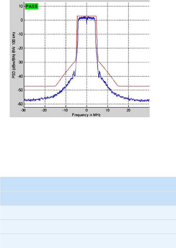
» More than +20dBm Class C RF spectrum mask compliant with margins at MMCX antenna port.
» Superior fading sensitivity in the typical ETSI defined C2C multipath scenarios increases wireless
coverage.
» Internal 40MHz BW filter provides immunity to out-of-band radio interferences in multi-channel
operation.
» Dual DSRC PHY supports concurrent dual channel operation.
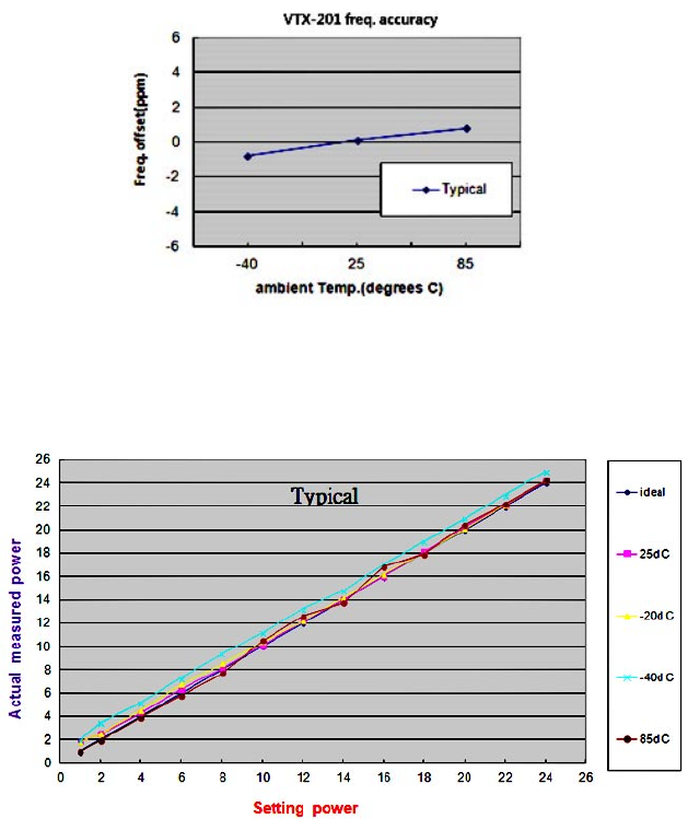
» Dedicated oscillator provides high frequency accuracy at ± 6.0ppm in –40ºC ~ +85ºC temperature
range.
» Dynamic and accurate power control in a wide 4.5dBm ~ 25dBm output range provides superior
performance stability.
» Integrated RF ESD protectors on antenna ports provide robust surge protection.
» High ESD protection design ensures immunity and robustness of all ports in ESD events. (IEC 61000-
4-2 Level 4, Contact ±8kV, Air ±15kV)
» 4-corner UV cured resin for BGA chips ensures vibrational and environmental reliability.
Performance:
» System on module design of Autotalks® Craton 3-CPU core communication processor, Pluton RF
transceiver, 128MB DDR3, and 32MB NOR enables V2X software applications on internal system, no
external CPU required.
» Automotive-grade -40ºC ~ +85ºC components and 50-pin header design secure environmental
reliability.
» Wide DC power input range from 6V ~ 40Vprovides application flexibility.
» Power management support of Idle, ON, and OFF state.
Subsystem:
» 50-pin header design provides feature rich I/O to meet connectivity requirement of V2X system
integration.
» Two on-board MMCX DIP antenna connectors provide robust RF performance up to 6GHz.
» Optional off-the-shelf hardware and software modules enable V2X OBU, V2X RSU, V2X Sensor
Fusion ECU applications.
Flexibility:
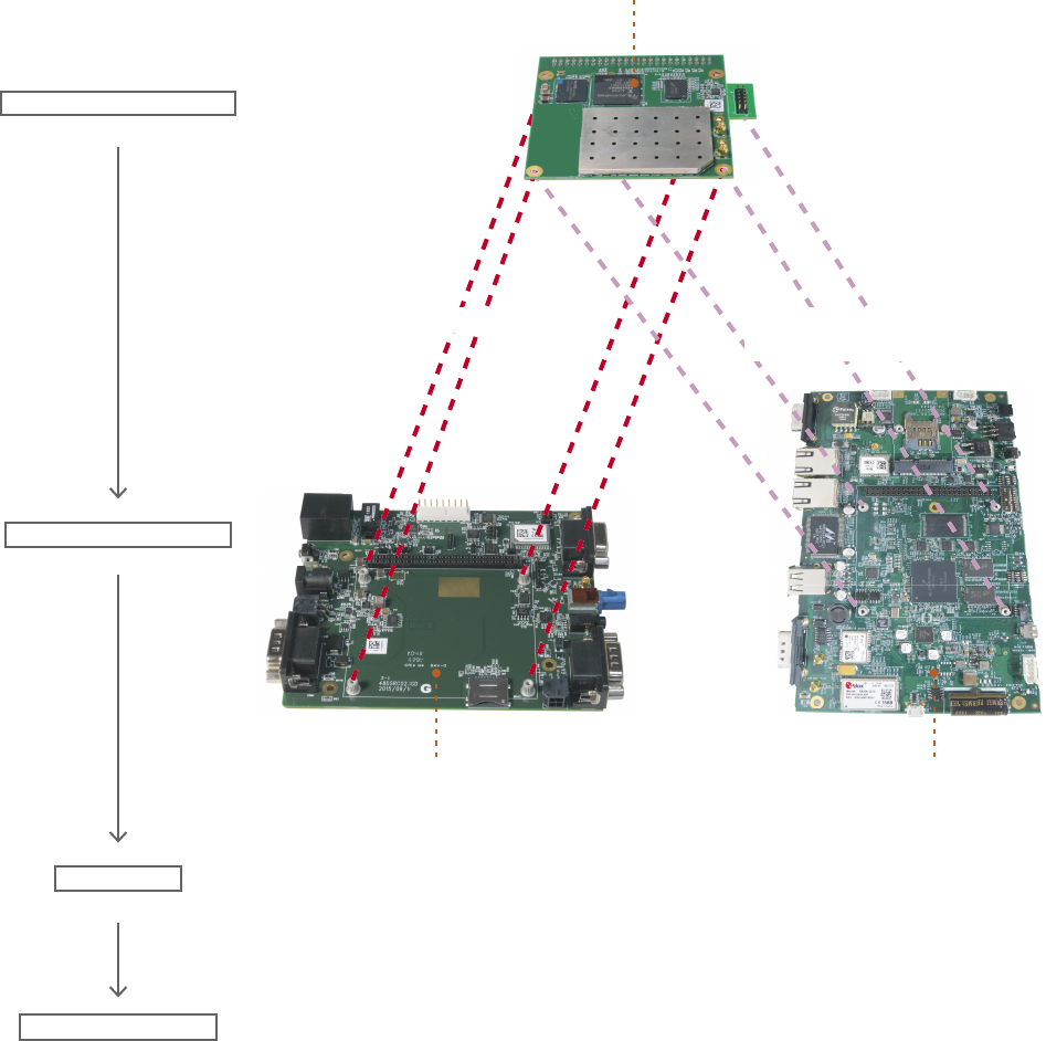
1. PCB-201: GNSS/HSM carrier board for VTX-201
2. HVP-201: i.MX 6/Cellular/GNSS/HSM main board for VTX-201
3. VPS-201x: V2X protocol stack license
4. VAS-201x: V2X application service
5. VVT-201x: diagnostic firmware in field deployment
[Unex] - Ver. 1.13- 20170307 spec. P. 3
PCB-201
GNSS/HSM carrier board
VTX-201
Craton/Pluton
HVP-201
i.MX 6/Cellular/HSM main board
typical: On-Board-Unit typical: Roadside-Unit or
V2X Sensor Fusion ECU
VTX-201 Carrier Board
DSRC Subsystem Module
IEEE1609.x or ETSI-TC ITS protocal stack
V2X Stack
V2X Applications CAMP VSC-A in US and Day-One App. in Eur.
[Unex] - Ver. 1.13- 20170307 spec. P. 4
1. Frequency Accuracy
2. Power Control Accuracy
[Unex] - Ver. 1.13- 20170307 spec. P. 5
4. Consistent EVM performance over a wide 5~22dBm power levels and -40ºC~+85ºC temperature range
provide high channel efficiency.
25 degrees C 85 degrees C -40 degrees C
TX2 TX1 TX2 TX1 TX2 TX1
dut1 -28 -28 -29 -27.8 -27.7 -27.5
dut2 -30.5 -27.5 -30 -27 -30 -27.4
dut3 -31.4 -26.3 -30.2 -28.8 -28 -27
[Unex] - Ver. 1.13- 20170307 spec. P. 6
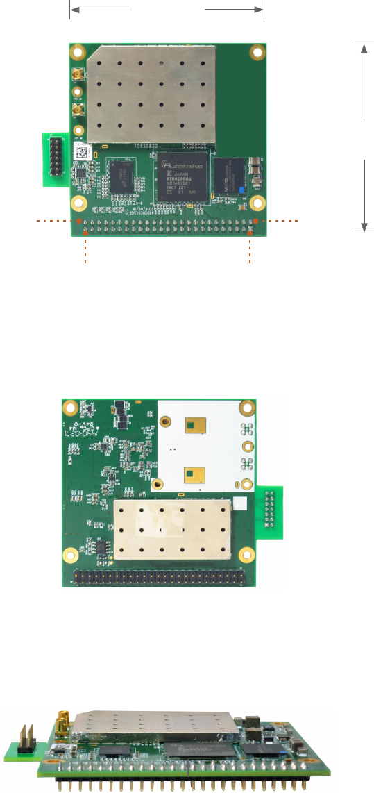
Top View
Back View
Side View
71.5mm
72.6mm
pin2
pin1pin49
pin50
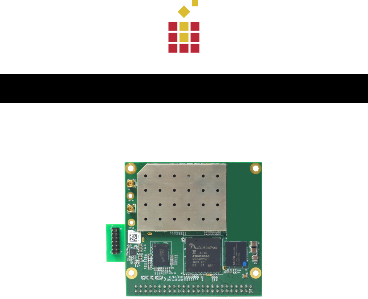
Gold plated pin: pitch 2.54mm, length2.5 ± 0.3mm

[Unex] - Ver. 1.13- 20170307 spec. P. 7
FUNCTION Signal Pin
Number
Signal FUNCTION
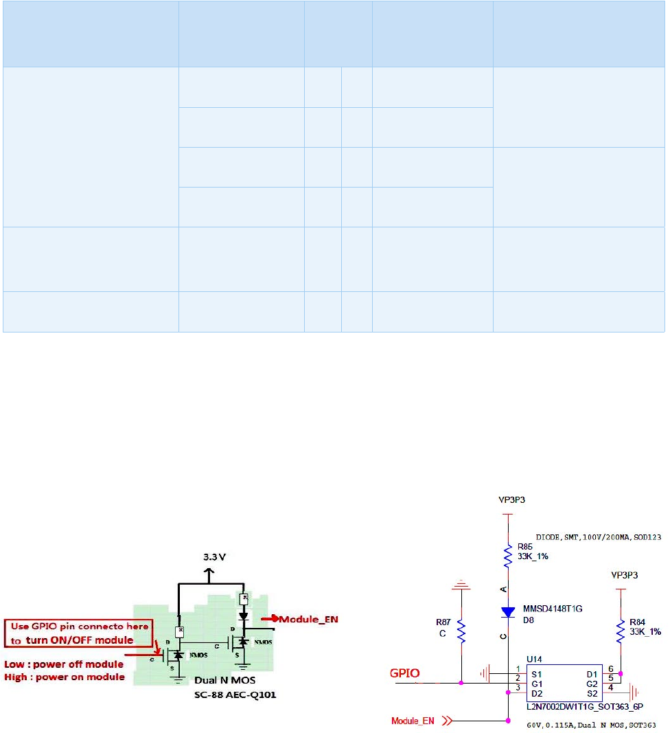
6~40V *a VCC 2 1 Module_EN Float this pin (internally conn. to
VCC), or use it *b
6~40V *a VCC 4 3 GND VSS
VSS GND 6 5 ETH_PHY_RESET_L Ethernet Reset
CAN0_Physical CAN0_H 8 7 Reset_n Reset_n: "0" then "1" to Reset
Dsrc module.
CAN0_L 10 9 SPI1_SCLK SPI1(default for uSD socket
connection)
CAN1_Digital CAN1_TXD 12 11 SPI1_TXD
CAN1_RXD 14 13 SPI1_RXD
Default HCI(RMII) RMII_MDC 16 15 SPI1_FRAME
RMII_MDIO 18 17 GND VSS
GND GND 20 19 I2C_SDA I²C Master(for I²C sensors, GPIO
expander, etc...)
Default HCI(RMII)
Noted: RXER could become
I2S_BCLK(GPIO20)
RMII_RXDV 22 21 I2C_SCL
RMII_RXER/I2S_BCLK 24 23 GND VSS
RMII_ERX0 26 25 SPI0_SCLK SPI0
RMII_ERX1 28 27 SPI0_TXD
RMII_CLK 30 29 SPI0_RXD
RMII_ETX1 32 31 SPI0_FRAME
RMII_ETX0 34 33 GND VSS
RMII_TXEN 36 35 PPS GNSS PPS signal
VSS GND 38 37 GPIO30 GPIO30: default for uSD CS pin)
[Unex] - Ver. 1.13- 20170307 spec. P. 8
*a : VCC require steady DC from 6~40V range. No automotive load dump protection circuit on this module.
*b : This pin is a internally connection to VCC (pin2 & pin4) for the control of whole module power system ON or
OFF state. Either float this pin or follow suggested ckt. below to power ON/OFF module through external
system GPIO.
FUNCTION Signal Pin
Number
Signal FUNCTION
Default for HSM(Infineon's
SLE97xx)
GPIO26/SPI2_SCLK 40 39 UART_0_TXD Console
GPIO27/SPI2_Frame 42 41 UART_0_RXD
GPIO25/SPI2_TXD 44 43 UART_1_TXD To GNSS module(Telit's SL869)
GPIO24/SPI2_RXD 46 45 UART_1_RXD
GPIO22/I2S_DATA GPIO22/I2S_DATA 48 47 GPS_ON_GPIO16 default: GPIO to turn on/off GNSS
module
GPIO1 GPIO1 50 49 GPIO21/I2S_WCLK CPIO21/I2S_WCLK

[Unex] - Ver. 1.13- 20170307 spec. P. 9
Operation System ThreadX RTOS
Chipset » Autotalks Craton (ATK4100) V2X communication processor, three
240MHz CPU cores.
» Autotalks Pluton (ATK3100) V2X RF Transceiver
Memory 32MB NOR system memory, 128MB DDR3 storage memory
Frequency Band 5.85 ~ 5.925 GHz (ITS-DSRC)
Radio Mode 802.11p, ITS-G
Channels 172, 174, 176, 178, 180, 182, 184
Channel
Bandwidth
10MHz (5MHz & 20MHz by project)
Data Rate 3, 4.5, 6, 9, 12, 18, 24, 27Mbps for 10MHz BW signal
Frequency
Accuracy
± 6.0ppm
RF Transmit
Power
> +20dBm, Class C RF spectrum mask compliant with margins

[Unex] - Ver. 1.13- 20170307 spec. P. 10
DSRC Static
Sensitivity
(typical, tolerance
+2 / -2dB)
Condi�ons -40°C +25°C +85°C
3Mbps -97dBm -93dBm -92dBm
4.5Mbps -97dBm -93dBm -92dBm
6Mbps -95dBm -91dBm -91dBm
9Mbps -93dBm -89dBm -89dBm
12Mbps -90dBm -86dBm -85dBm
18Mbps -86dBm -83dBm -83dBm
24Mbps -80dBm -75dBm -75dBm
27Mbps -78dBm -74dBm -73dBm
DSRC Fading
Sensitivity
» Power @ 10% PER sensitivity (6Mbps, 1000B packet), fading channels as 5
typical C2C multipath scenarios defined by ETSI: ± 2dBm
» Rural LOS: -92.5dBm
» Highway LOS: -91.5dBm
» Urban Approaching LOS: -91.5dBm
» Crossing NLOS: -89.5dBm
» Highway NLOS: -88.5dBm
Operation
Voltage
DC 6.0 ~ 40V ± 5%
Power
Consumption 12V power input
Condi�ons 25°C 85°C -40°C
Tx @ 20~8dBm
(RF duty cycle = 7%)
0.3A 0.315A 0.3A
Idle 0.29A 0.3A 0.29A

[Unex] - Ver. 1.13- 20170307 spec. P. 11
On-board
Interface
proprietary gold plated 50-pin (pitch 2.54 mm, length2.5 ± 0.3mm) supports:
» two CAN : one physical CAN with transceiver and one digital CAN
» RMII for Ethernet or external CPU integration
» SPI reserved for external Infineon SLE97xx HSM (default)
» SPI reserved for external microSD flash memory (default)
» SPI reserved for external SPI-to-USB converter (optional)
» I2C master for I2C sensors or GPIO expander (default)
» I2S reserved for audio codec (default)
» PPS for GNSS PPS signal input
» UART reserved for console and external Telit SL869 GNSS (default)
details per Pin Definition as above page
Antenna
Connector
two MMCX DIP antenna connectors
Operation
Temperature
Range
ambient: -40ºC ~ +85ºC
Storage
Temperature
Range
-45ºC ~ +90ºC
Operating
Humidity
10% - 95%, non-condensing
Storage Humidity max. 95%, non-condensing

[Unex] - Ver. 1.13- 20170307 spec. P. 12
VTX-201 DSRC V2X Subsystem, Autotalks® Craton/Pluton
VTX-201E DSRC V2X Subsystem, preloaded ETSI TC-ITS protocol stack
VTX-201U DSRC V2X Subsystem, preloaded IEEE 1609.x protocol stack
Environment-
Friendly
Compliance
REACH and RoHS
Dimension 72.6 mm(L) x 71.5mm(W)

[Unex] - Ver. 1.13- 20170307 spec. P. 13
PCB-201 GNSS/HSM Carrier Board, SL869/SLE97
HVP-201 i.MX 6/Cellular/GNSS/HSM Main Board, iMX6/Sara/SL869/SLE97
VPS-201x IEEE 1609.x and/or ETSI TC-ITS V2X protocol stack
VAS-201x CAMP VSC-A or ETSI TC-ITS Day-One or field V2X applications
VVT-201 V2X Diagnostic Firmware
sales-a@unex.com.tw
http://www.unex.com.tw
[Unex] - Ver. 1.13- 20170307 spec. P. 14
- All Connected
OBU-201 V2X On-Board Unit
OBU-201E V2X On-Board Unit, ETSI TC-ITS protocol stack
OBU-201U V2X On-Board Unit, 1609.x protocol stack
RSU-101 V2X Enabling Roadside Unit
RSU-101E V2X Enabling Roadside Unit, ETSI TC-ITS protocol stack
RSU-101U V2X Enabling Roadside Unit, 1609.x protocol stack
RSU-201 V2X Roadside Unit
RSU-201E V2X Roadside Unit, ETSI TC-ITS protocol stack
RSU-201U V2X Roadside Unit, 1609.x protocol stack