Unication Co R01VHF VHF REPEATER - FIXED MOUNTED User Manual
Unication Co Ltd VHF REPEATER - FIXED MOUNTED
UserManual.wiki
>
Unication Co
>
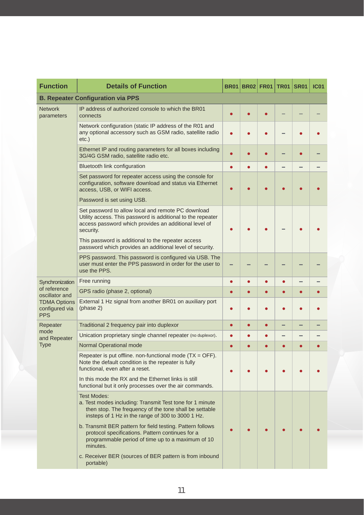
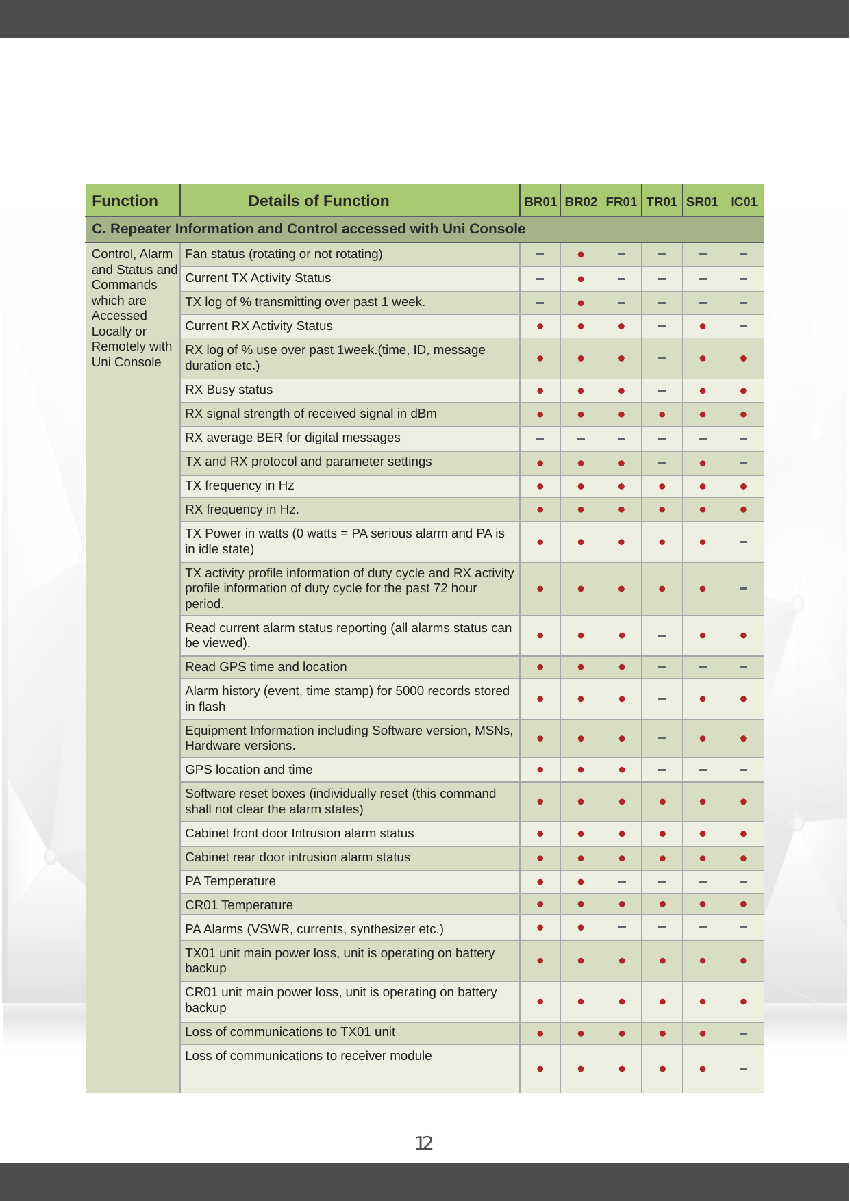
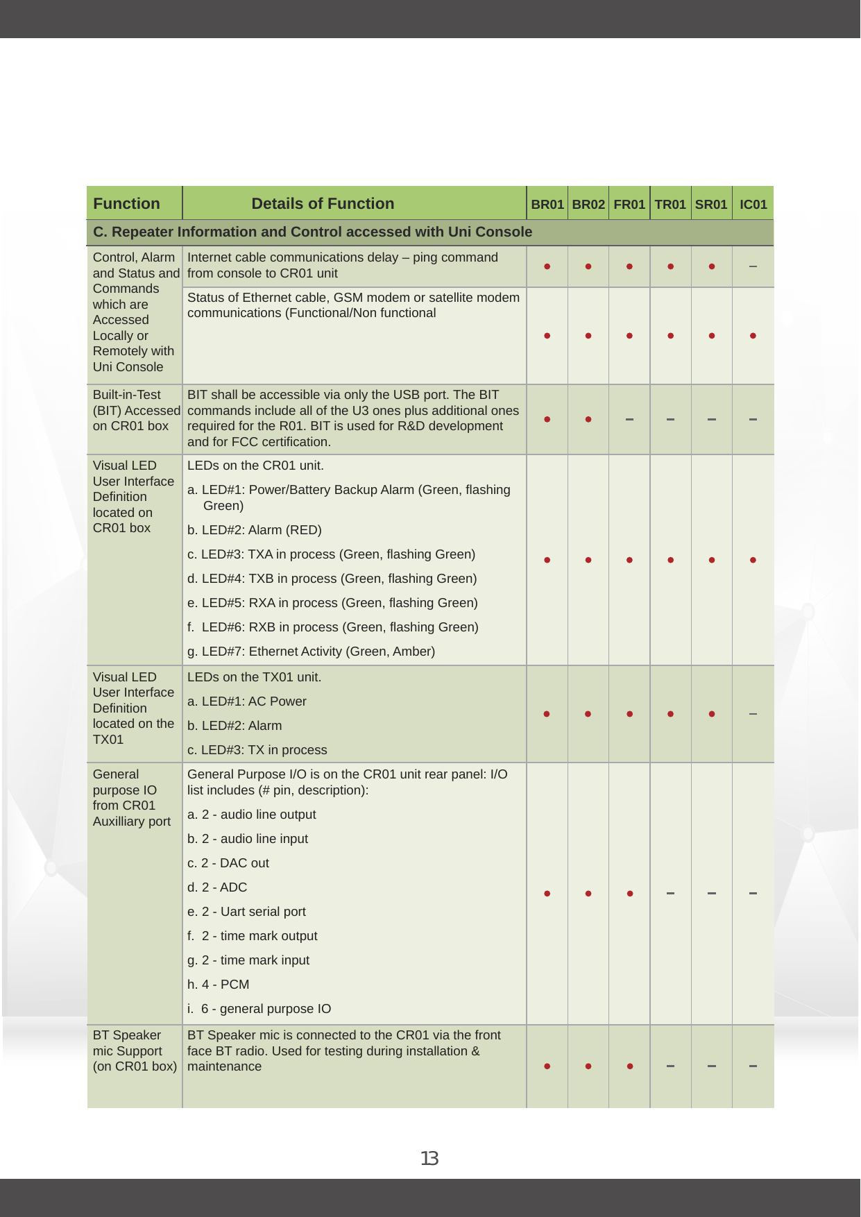
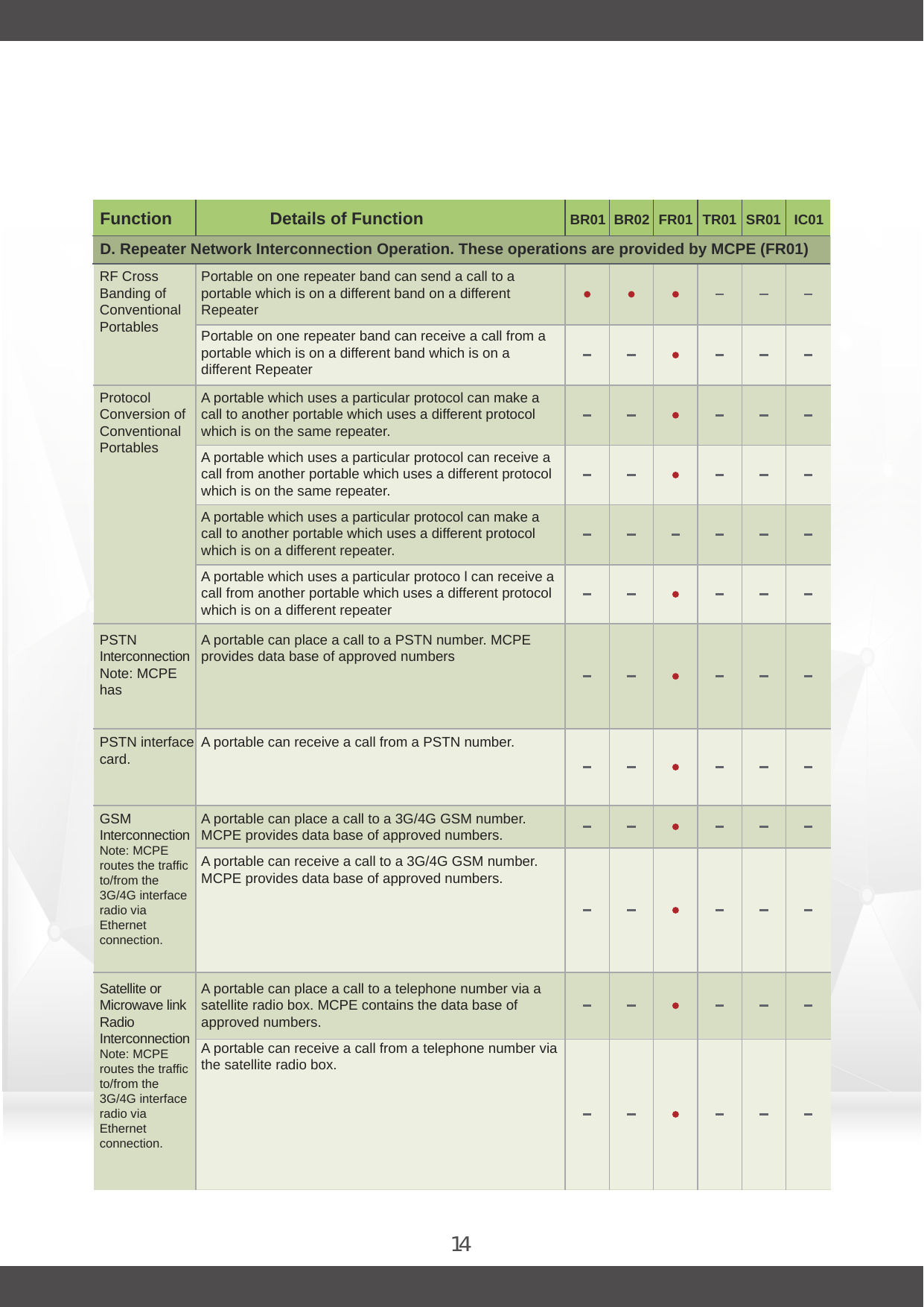
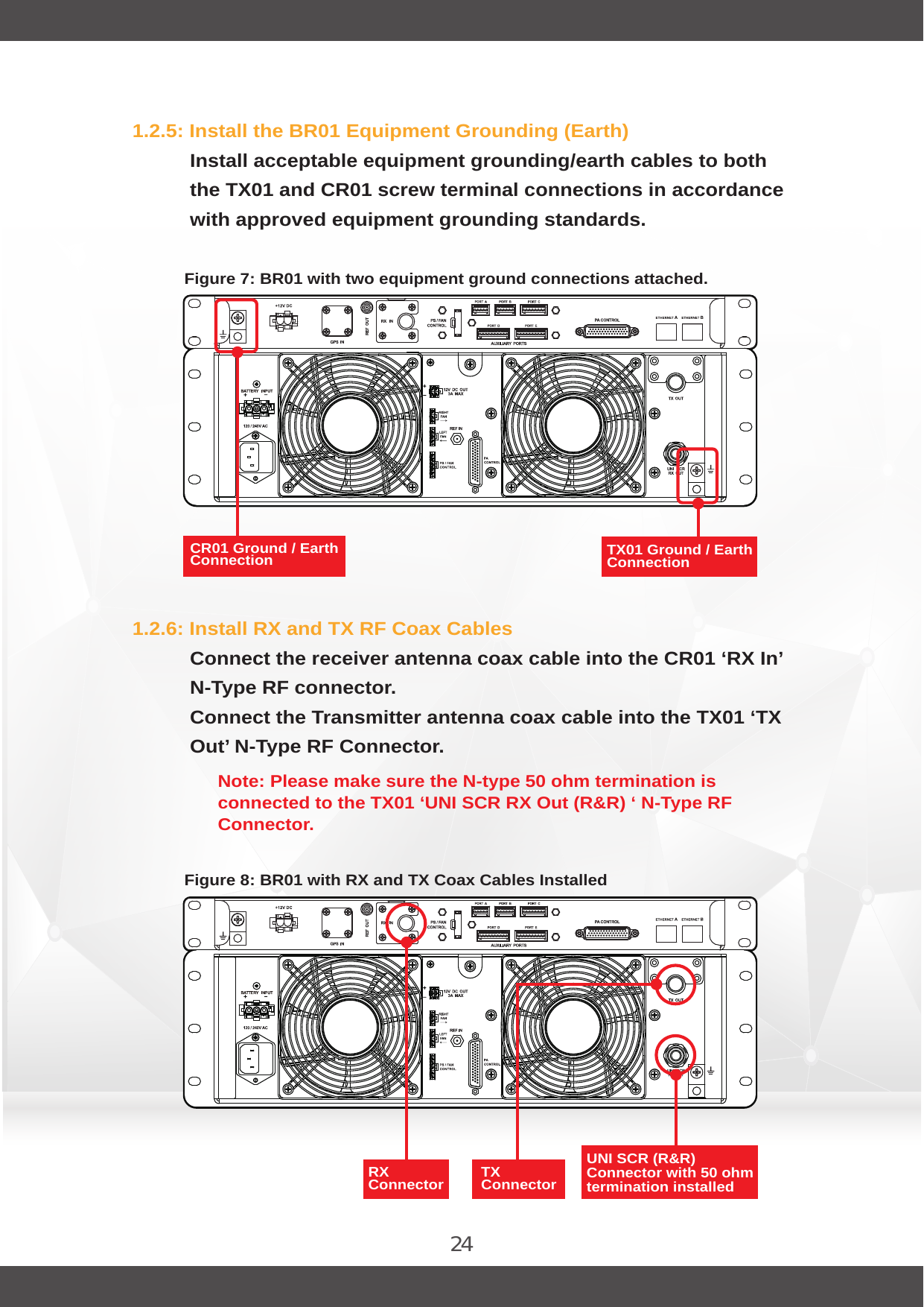
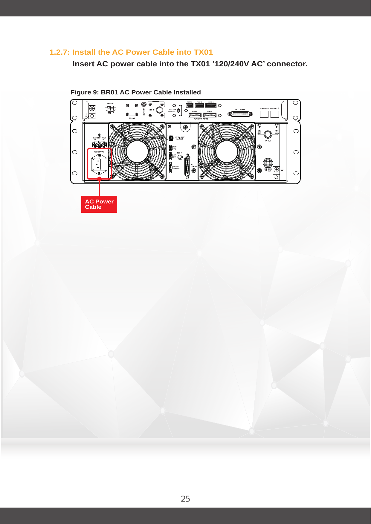
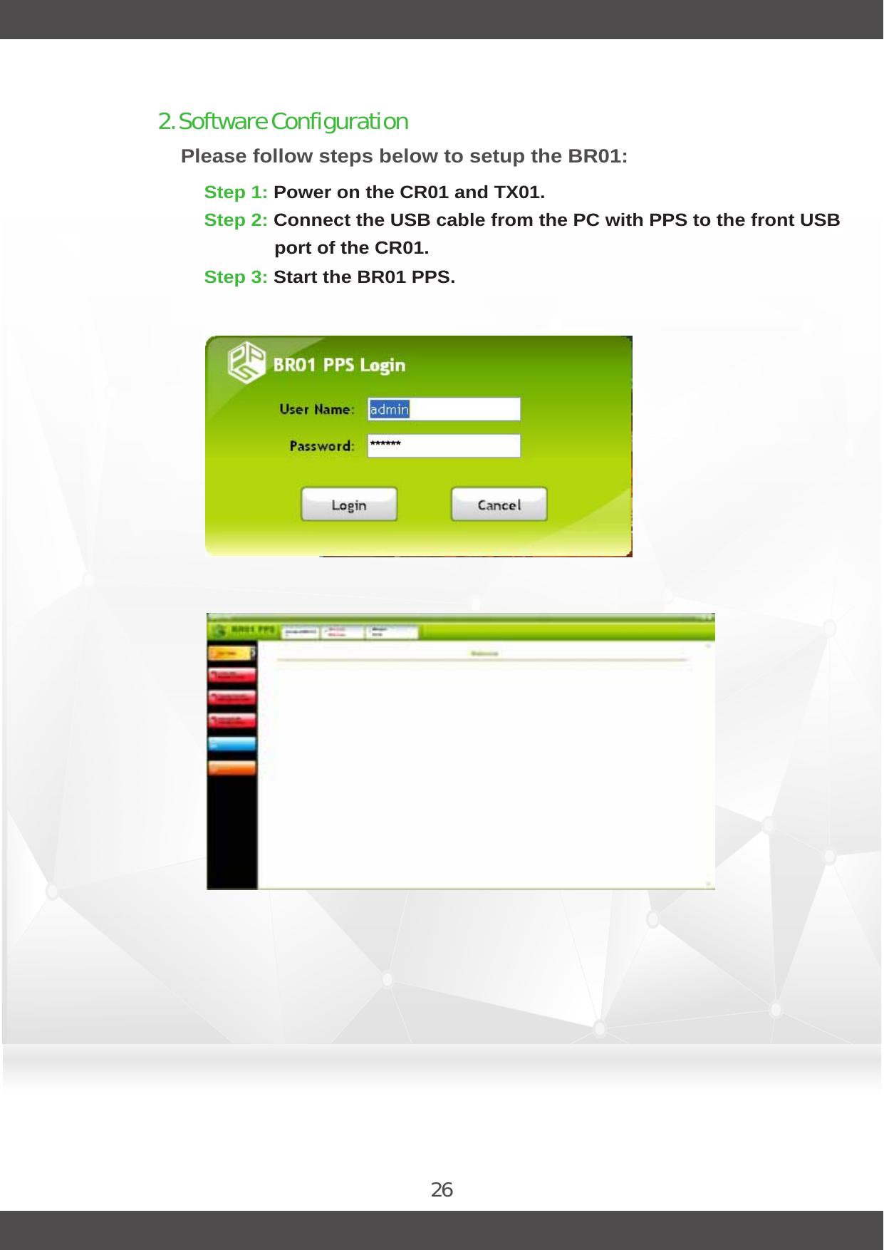
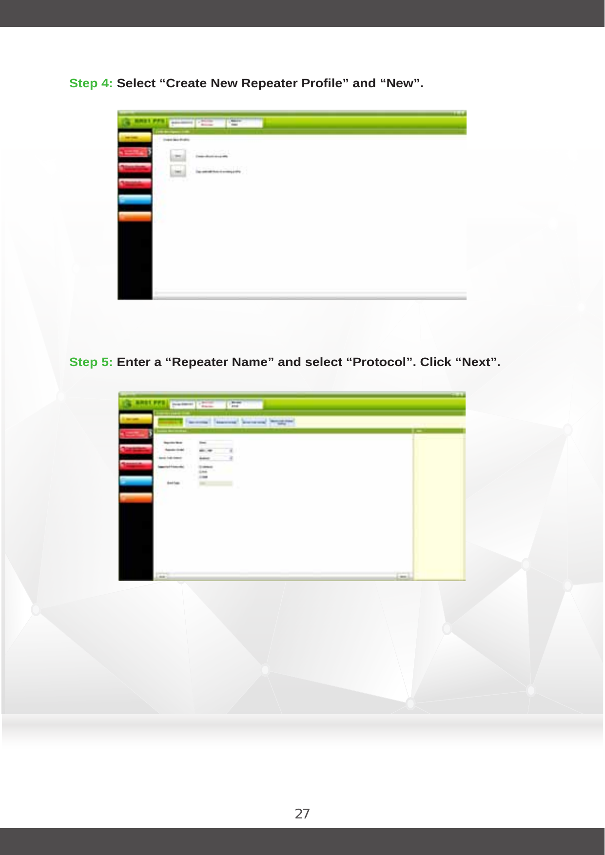
R01VHF User Manual
User Manual
Navigation menu
Upload a User Manual
Namespaces
Wiki Guide
HTML
PDF
Info
Views
User Manual
Discussion / Help
Navigation