Uniden America UB328 PORTABLE TYPE SCANNER User Manual BCD396T Paper OM
Uniden America Corporation PORTABLE TYPE SCANNER BCD396T Paper OM
UserManual.wiki
>
Uniden America
>
UB328 User Manual
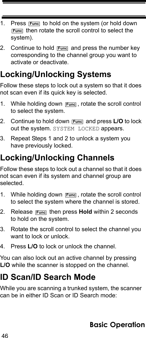
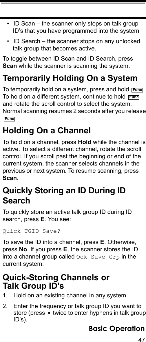
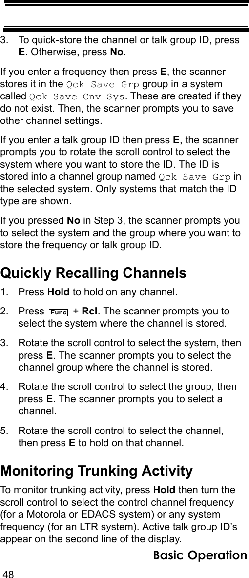
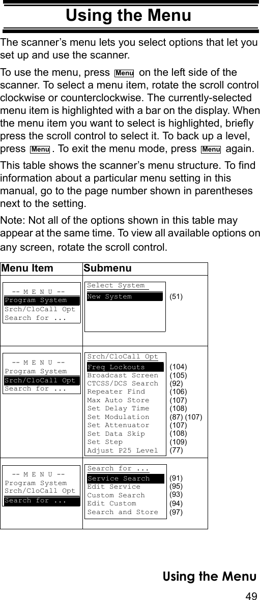
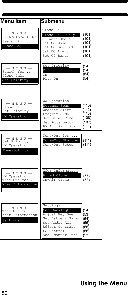
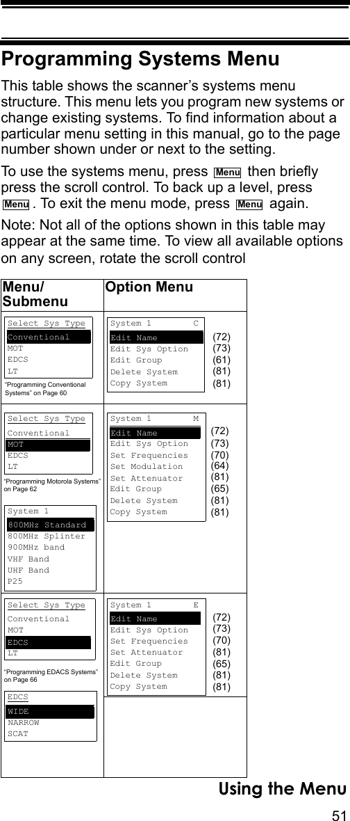
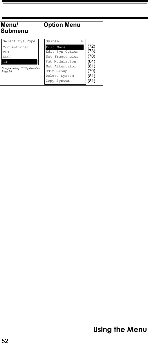
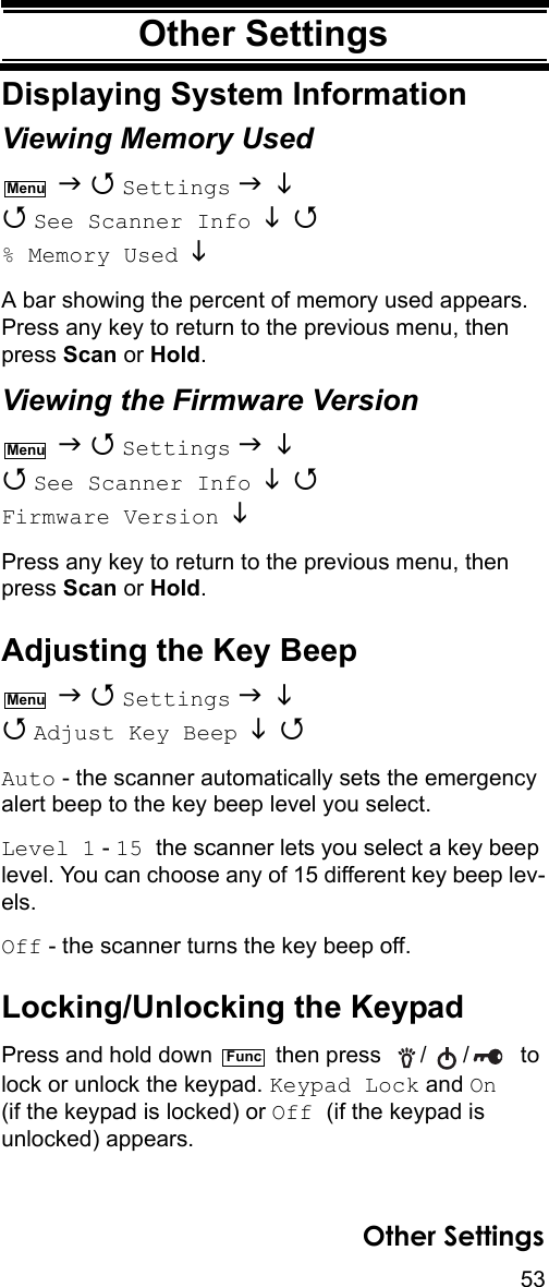
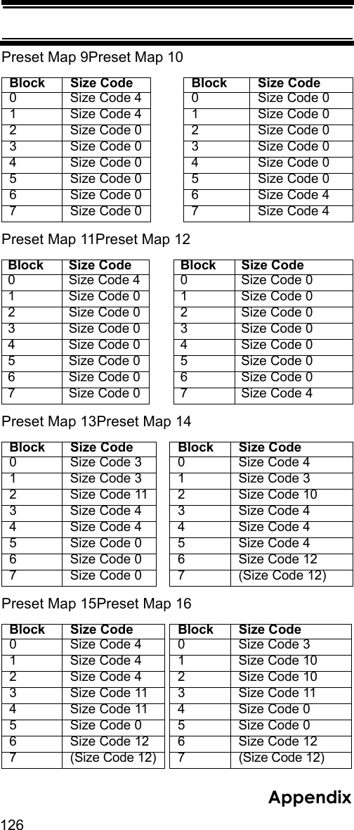
USERS MANUAL
Navigation menu
Upload a User Manual
Namespaces
Wiki Guide
HTML
PDF
Info
Views
User Manual
Discussion / Help
Navigation