Uniden America UB330 Portable Scanner User Manual BR330T Paper OM
Uniden America Corporation Portable Scanner BR330T Paper OM
UserManual.wiki
>
Uniden America
>
UB330 User Manual
users manual
Navigation menu
Upload a User Manual
Namespaces
Wiki Guide
HTML
PDF
Info
Views
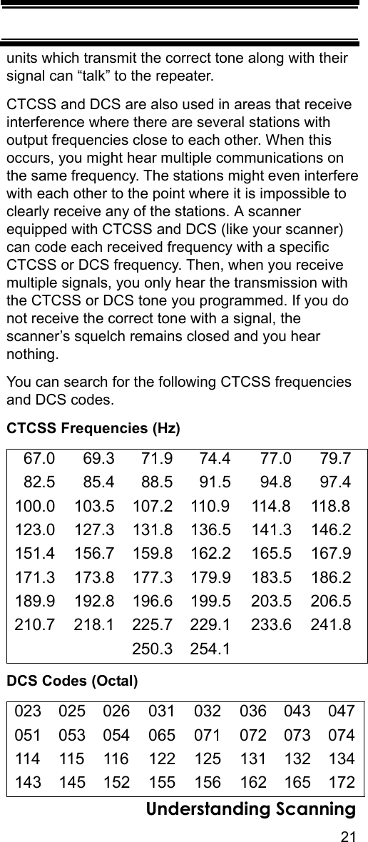
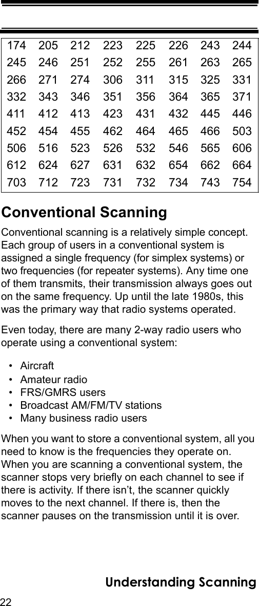
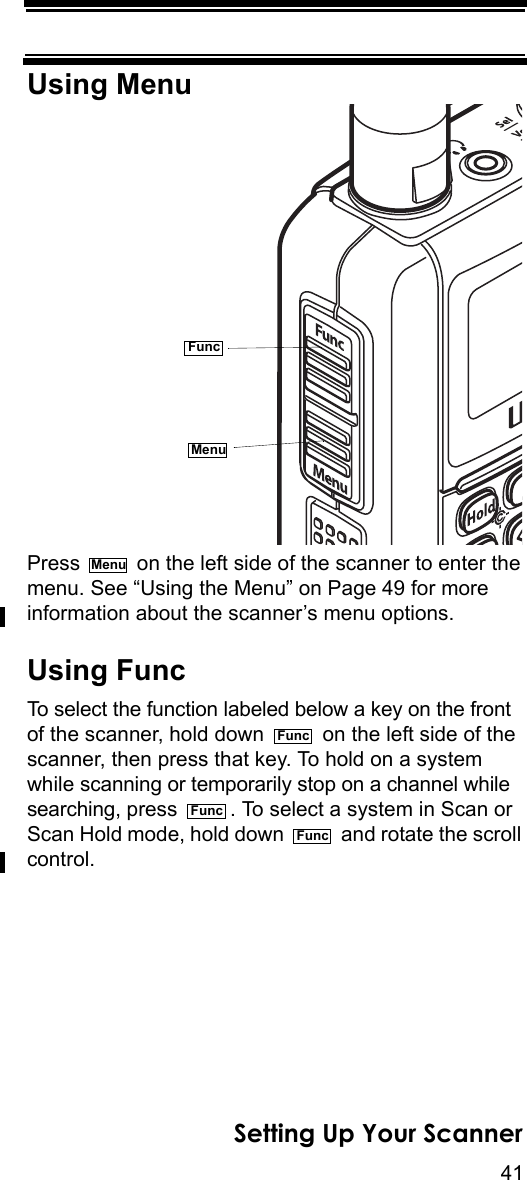
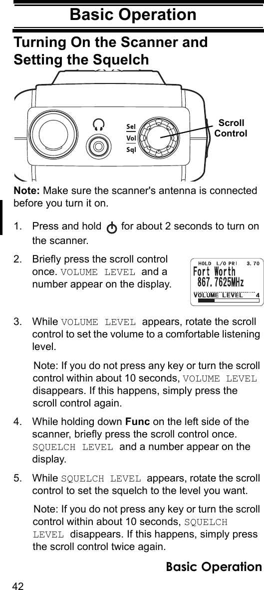
User Manual
Discussion / Help
Navigation