Uniden America UB335 MOBILE TYPE DIGITAL TRUNKING SCANNER User Manual 1
Uniden America Corporation MOBILE TYPE DIGITAL TRUNKING SCANNER 1
users manual
BC340CRS
OWNER’S
INSTRUCTION MANUAL
DRAFT
MODEL: BCD996T
FCC ID: AMWUB335

Before you use this scanner, please read and observe the following.
IMPORTANT!
This scanning radio has been manufactured so that it will not tune to the
radio frequencies assigned by the FCC for cellular telephone usage. The
Electronic Communications Privacy Act of 1986, as amended, makes it a
federal crime to intentionally intercept cellular or cordless telephone
transmissions or to market this radio when altered to receive them. The
installation, possession, or use of this scanning radio in a motor vehicle
may be prohibited, regulated, or require a permit in certain states, cities,
and/or local jurisdictions. Your local law enforcement officials should be
able to provide you with information regarding the laws in your
community.
Changes or modifications to this product not expressly approved by
Uniden, or operation of this product in any way other than as detailed by
this Operating Guide, could void your authority to operate this product.
EARPHONE WARNING!
You can use an optional 32 Ωstereo headset or earphone with this
scanner. Use of an incorrect earphone or stereo headset might be
potentially hazardous to your hearing. The output of the phone jack is
monaural, but you will hear it in both headphones of a stereo headset.
Set the speaker volume to a comfortable level before plugging in either a
monaural earphone or a stereo headset of the proper impedance (32 Ω).
Otherwise, you might experience some discomfort or possible hearing
damage if the volume suddenly becomes too loud because of the volume
control or squelch control setting. This is particularly true for the type of
earphone that is placed in the ear canal.
2
Precautions
Precautions
UB337ZH(BC340CRS)_new 11/29/05 7:24 PM Page 2

WARNING!
Uniden does not represent this unit to be waterproof. To reduce the risk
of fire or electrical shock, do not expose this unit to rain or moisture.
Uniden®and Bearcat®are registered trademarks of Uniden America
Corporation.
Other trademarks used throughout this manual are the property of their
respective holders.
Important: If you use the supplied AC adapter to power the scanner but
have not installed batteries in the scanner, never turn the scanner off by
disconnecting the AC adapter or unplugging it from the AC outlet. This
might corrupt the scanner’s memory. Always use POWER to turn the
scanner off before disconnecting AC power.
3
Precautions
UB337ZH(BC340CRS)_new 11/29/05 7:24 PM Page 3

This scanner has been tested and found to comply with the limits for a
scanning receiver, pursuant to Part 15 of the FCC Rules. These limits are
designed to provide reasonable protection against harmful interference in
a residential installation. This scanner generates, uses, and can radiate
radio frequency energy and, if not installed and used in accordance with
the instructions, may cause harmful interference to radio communications.
There is no guarantee that interference will not occur in a particular
installation. If this scanner does cause harmful interference to radio or
television reception, which can be determined by turning the scanner on
and off, you are encouraged to try to correct the interference by one or
more of the following measures:
• Reorient or relocate the receiving antenna
• Increase the separation between the scanner and the receiver
This device complies with Part 15 of the FCC Rules. Operation is subject
to the following two conditions: 1) This device may not cause harmful
interference, and 2) this device must accept any interference received,
including interference that may cause undesired operation.
Scanning Legally
Your scanner covers frequencies used by many different groups,
including police and fire departments, ambulance services, government
agencies, private companies, amateur radio services, military operations,
pager services, and wireline (telephone and telegraph) service providers.
It is legal to listen to almost every transmission your scanner can receive.
However, there are some transmissions that you should never
intentionally listen to. These include:
• Telephone conversations (cellular, cordless, or other private means of
telephone signal transmission)
• Pager transmissions
• Any scrambled or encrypted transmissions
According to the Electronic Communications Privacy Act (ECPA), you are
subject to fines and possible imprisonment for intentionally listening to,
using, or divulging the contents of such a conversation unless you have
the consent of a party to the conversation (unless such activity is
otherwise illegal). This scanner has been designed to prevent the
reception of cellular telephone transmissions and the decoding of
scrambled transmissions.
6
The FCC Wants You to Know
The FCC Wants You to Know
UB337ZH(BC340CRS)_new 11/29/05 7:24 PM Page 6

This is done to comply with the legal requirement that scanners be
manufactured so they are not easy to modify to pick up these
transmissions. Do not open your scanner’s case to make any
modifications that could allow it to pick up transmissions that are illegal to
monitor. Modifying or tampering with your scanner’s internal components
or using it in a way other than as described in this manual could
invalidate your warranty and void your FCC authorization to operate it. In
some areas, mobile and/or portable use of this scanner is unlawful or
requires a permit. Check the laws in your area. It is also illegal in many
areas (and a bad idea everywhere) to interfere with the duties of public
safety officials by traveling to the scene of an incident without
authorization.
7
The FCC Wants You to Know
UB337ZH(BC340CRS)_new 11/29/05 7:24 PM Page 7

28
Care and Maintenance
Care and Maintenance
General Use
• Turn the scanner off before disconnecting the power.
• If memory is lost, simply reprogram each channel.
• Always press each button firmly until you hear the entry tone for that
key entry.
Location
• Do not use the scanner in high-moisture environments such as the
kitchen or bathroom.
• Avoid placing the unit in direct sunlight or near heating elements or
vents.
• If the scanner receives strong interference or electrical noise, move it
or its antenna away from the source of the noise. If possible, a higher
elevation might provide better reception.
• Also try changing the height or angle of the antenna.
Cleaning
• Disconnect the power to the unit before cleaning.
• Clean the outside of the scanner with a mild detergent.
• To prevent scratches, do not use abrasive cleaners or solvents. Be
careful not to rub the LCD window.
• Do not use excessive amounts of water.
Repairs
Do not attempt any repair. The scanner contains no user serviceable
parts. Contact the Uniden Customer Service Center or take it to a
qualified repair technician.
Birdies
All radios can receive “birdies” (undesired signals). If your scanner stops
during Scan mode and no sound is heard, it might be receiving a birdie.
Birdies are internally generated signals inherent in the electronics of the
scanner. Press L/O to lock out the channel.
Resetting the Scanner (Clearing all Memories)
To reset the scanner to factory defaults, turn off the scanner. Then, while
holding down 2, 9, and HOLD, turn on the scanner. All scanner memory
contents are erased.
UB337ZH(BC340CRS)_new 11/29/05 7:25 PM Page 28

29
One-Year Limited Warranty
One-Year Limited Warranty
Important: Evidence of original purchase is required for warranty
service.
WARRANTOR: UNIDEN AMERICA CORPORATION (“Uniden”)
ELEMENTS OF WARRANTY: Uniden warrants, for one year, to the
original retail owner, this Uniden Product to be free from defects in
materials and craftsmanship with only the limitations or exclusions set out
below.
WARRANTY DURATION: This warranty to the original user shall
terminate and be of no further effect 12 months after the date of original
retail sale. The warranty is invalid if the Product is (A) damaged or not
maintained as reasonable or necessary, (B) modified, altered, or used as
part of any conversion kits, subassemblies, or any configurations not sold
by Uniden, (C) improperly installed, (D) serviced or repaired by someone
other than an authorized Uniden service center for a defect or malfunction
covered by this warranty, (E) used in any conjunction with equipment or
parts or as part of any system not manufactured by Uniden, or (F)
installed or programmed by anyone other than as detailed by the
Operating Guide for this product.
STATEMENT OF REMEDY: In the event that the product does not
conform to this warranty at any time while this warranty is in effect,
warrantor will repair the defect and return it to you without charge for
parts, service, or any other cost (except shipping and handling) incurred
by warrantor or its representatives in connection with the performance of
this warranty. THE LIMITED WARRANTY SET FORTH ABOVE IS THE
SOLE AND ENTIRE WARRANTY PERTAINING TO THE PRODUCT AND
IS IN LIEU OF AND EXCLUDES ALL OTHER WARRANTIES OF ANY
NATURE WHATSOEVER, WHETHER EXPRESS, IMPLIED OR ARISING
BY OPERATION OF LAW, INCLUDING, BUT NOT LIMITED TO ANY
IMPLIED WARRANTIES OF MERCHANTABILITY OR FITNESS FOR A
PARTICULAR PURPOSE. THIS WARRANTY DOES NOT COVER OR
PROVIDE FOR THE REIMBURSEMENT OR PAYMENT OF INCIDENTAL
OR CONSEQUENTIAL DAMAGES. Some states do not allow this
exclusion or limitation of incidental or consequential damages so the
above limitation or exclusion might not apply to you.
LEGAL REMEDIES: This warranty gives you specific legal rights, and
you might also have other rights which vary from state to state. This
warranty is void outside the United States of America.
UB337ZH(BC340CRS)_new 11/29/05 7:25 PM Page 29

30
One-Year Limited Warranty
PROCEDURE FOR OBTAINING PERFORMANCE OF WARRANTY: If,
after following the instructions in this Operating Guide you are certain that
the Product is defective, pack the Product carefully (preferably in its
original packaging). Include evidence of original purchase and a note
describing the defect that has caused you to return it. The Product should
be shipped freight prepaid, by traceable means, or delivered, to warrantor
at:
Uniden America Corporation
Parts and Service Division
4700 Amon Carter Boulevard
Fort Worth, TX 76155
(800) 297-1023, 8:00 a.m. to 5:00 p.m., Central,
Monday through Friday
UB337ZH(BC340CRS)_new 11/29/05 7:25 PM Page 30

1. FEATURE SUMMARY
1.1. BAND COVERAGE
Frequency (MHz)
Lower Edge Upper Edge Modulation Step (kHz) Remark
25.0000 26.9600 AM 5.0 Petroleum Products
& Broadcast Pickup
26.9650 27.4050 AM 5.0 CB Class D Channel
27.4100 27.9950 AM 5.0 Business & Forest Products
28.0000 29.6800 NFM 20.0 10 Meter Amateur Band
29.7000 49.9900 NFM 10.0 VHF Low Band
50.0000 53.9800 NFM 20.0 6 Meter Amateur Band
54.0000 71.9500 WFM 50.0 VHF TV Broadcast 2 – 4
72.0000 75.9950 FM 5.0 Intersystem & Astronomy
76.0000 87.9500 WFM 50.0 VHF TV Broadcast 5 – 6
88.0000 107.9000 WFM 100.0 FM Broadcast
108.0000 136.9750 AM 25.0 Aircraft Band
137.0000 143.9875 NFM 12.5 Military Land Mobile
144.0000 147.9950 NFM 5.0 2 Meter Amateur Band
148.0000 150.7875 NFM 12.5 Military Land Mobile
150.8000 161.9950 NFM 5.0 VHF High Band
162.0000 173.9875 NFM 12.5 Federal Government
174.0000 215.9500 WFM 50.0 TV Broadcast 7 – 13
216.0000 224.9800 NFM 20.0 1.25 Meter Amateur Band
225.0000 399.9500 AM 50.0 UHF Aircraft Band
400.0000 405.9875 NFM 12.5 Miscellaneous
406.0000 419.9875 NFM 12.5 Federal Government Land Mobile
420.0000 449.9875 NFM 12.5 70 cm Amateur Band
450.0000 469.9875 NFM 12.5 UHF Standard Band
470.0000 512.0000 NFM 12.5 UHF TV
764.0000 775.9875 NFM 12.5 Public Service Band
794.0000 805.9875 NFM 12.5 Public Service Band
806.0000 823.9875 NFM 12.5 Public Service Band
849.0125 868.9875 NFM 12.5 Public Service Band
894.0125 956.0000 NFM 12.5 Public Service Band
1240.0000 1300.0000 NFM 25.0 25 cm Amateur Band

* These Frequency Ranges suit to initial step setting. They will be changed by Step
setting.
* These Modulations are initial settings. They can be selected from AM / FM / NFM /
WFM / AUTO.
* These Steps are initial settings.
* Steps can be selected from 5 / 6.25 / 7.5 / 8.33 / 10 / 12.5 / 15 / 20 / 25 / 50 / 100 /
AUTO (kHz).
* If "AUTO" is selected for Modulation or Step, the scanner works with the modulation or
step of this table.
* If the Step is set to 15 kHz, inputable frequencies are xxx.x000, xxx.x150, xxx.x300,
xxx.x450, xxx.x600, xxx.x750, and xxx.x900. For example, the next frequency of
400.0900 MHz is 400.1000 MHz.
*If the Step is set to 8.33kHz, inputable frequencies are xxx.x000, xxx.x083, xxx.x166,
xxx.x250, xxx.x333, xxx.x416, xxx.x500, xxx.x583, xxx.x666, xxx.x750, xxx.x833, and
xxx.916.
For example, the next frequency of 100.0916 MHz is 100.1000 MHz.
* For 7.5 kHz Step, frequencies between 150.8150 and 154.6250 MHz is multiple of 7.5
kHz on the basis of 150.8150 MHz. For example, the next frequency of 150.8100 MHz is
150.8150 MHz, and the next frequency of 154.6250 MHz is 154.6275 MHz.
1.2. CHANNELS
Dynamic - The user can create conventional Channels, trunked Channels, trunked
System frequencies, and GPS locations up to 6000 in total.
*Channels belonging to conventional System have a frequency.
*Channels belonging to trunked System have a talkgroup ID.
*Channels belonging to location systems have Lat/Lon type information only.
*Creating Systems and Channel Groups reduces the number of total channels available.
1.3. MEMORY ARCHITECTURE
Dynamic allocation.
Construction:
400 Systems, 6000 Channels
*Construction will have some difference by System type and so on.
The limit of Systems: 400
The limit of Groups: 20 in System 20 in a System
The limit of Channels and System frequency: 6000
The limit of Channels in trunked System (= talkgroup ID): 200 in a System200
*These numbers are not creatable numbers. Creatable number changes by ratio of
conventional System, trunked System, Group, and Channel for conventional System,
Channel for trunked System, etc.
*The user can check the percent of the Memory currently used by Menu Mode.
1.4. CHANNEL MEMORY SCAN
The user can scan Channels already programmed.
ItThe scanner can track both conventional and trunked System at the same time.

1.5. SEARCH WITH SCAN
The scanner can do Service Search and Custom Search with Scan sequentially.
1.6. LOCKOUT FUNCTION FOR SCANNING
The user can lock out any System, Group and Channel.
Locked out Channel will be skipped during scanning. Location channels that are locked
out will be ignored.
If the System or Group is locked out, the Channels belonging to that will be skipped
during scanning.
The user can temporarily lockout a channel (it will be unlocked after power cycles) or
“permanently” lockout a channel.
1.7. QUICK KEY
There are 10 Quick Keys corresponding to numeric keypad (1 - 9, 0).
The Scanner has a setting of Quick Key for Systems. And each System has a setting of
Quick Key for Groups.
Systems or Groups are locked out or unlocked quickly while scanning by Quick Key
FeatureThe user can set Quick keys on systems or groups.
The System can set Quick Key from “0” to “99”. (Detail:
エラー
!
参照元が見つかりませ
ん。
.
エラー
!
参照元が見つかりません。
.)
The Group can set it from 1 to 9 and 0.
The user can turn on or Off Quick Key of the system by the keypad.
1.8. PRIORITY SCAN
The scanner checks conventional Priority Channels every 2 seconds while scanning a
conventional System.
1.9. PRIORITY PLUS
The scanner scans only Priority Channels.
1.10. CHANNEL ALERT
The user can set this function for each Channel.
This function alerts the user when the Channel becomes active.
1.11. DROPOUT DELAY
Controls whether the scanner pauses at the end of a transmission to wait for a reply.
The user can set the Delay time for each System. All Channels in the System share the
same delay setting.
The user can also set the Delay time for Search, Close Call and Tone-Out.

1.12. ATTENUATOR
The user can attenuate the strength of the strong signal inputted.
1.13. REPEATER REVERSE
One-touch key lets user switch to hearing the input frequency on a conventional
repeater system or trunked system.
1.14. QUICK RECALL
The user can quickly select a specific Channel by choosing the System, Group, and
Channel.
1.15. WEATHER AND SAME ALERT
The scanner can alert to Weather Alert Tone, all FIPS or selected FIPS.
1.16. CUSTOM SEARCH
The user can program Custom Search Ranges up to 10, and the user can search these
Ranges sequentially.
1.17. SERVICE SEARCH
The user can select the kind and search preprogrammed frequencies.
The kind of Service Search is as follows.
Public Safety, News, HAM Radio, Marine, Railroad, Air, CB Radio, FRS/GMRS,
Racing,
TV Broadcast, FM Broadcast, Special, Military Air
1.18. CODE SEARCH
Rapid search for the CTCSS/DCS used during a transmission.
The scanner does not detect or decode P25 signals if you are operating CTCSS/DCS
Search.
1.19. Tone-Out-SEQUENTIAL DECODE
Mute and alert control for Tone-Out Sequential.
1.20. FREQUENCY AUTOSTORE
SThe scanner searches frequencies and stores new found frequencies into a specified
System.

1.21. ID AUTOSTORE
SThe scanner searches talkgroup ID’s and stores new found ID’s into a specified
System.
1.22. QUICK SEARCH
If the user stops on a Channel in a conventional System, the user can start searching
from the current frequency.
If the user stops on a Channel in a trunked System, the user can begin trunk ID
searching in the System.
1.23. LOCKOUT FUNCTION FOR SEARCHING
The user can lock out any frequency up to 200.
Locked out frequencies will be skipped in Search Mode or Close Call Mode.
And the user can review all locked out frequencies in Menu Mode.
1.24. DATA NAMING
The user can name to each System, Group, Channel, Talkgroup ID, Custom Search
Range and SAME Group. The scanner allows up to 16 characters for each name.
1.25. DUPLICATE INPUT ALERT
The scanner will inform the user that now inputted Name, frequency and so on had
already stored in Memory or in same System.
1.26. DATA SKIP
Allows the scanner to skip unwanted data transmissions and reduces birdies.
1.27. BROADCAST SCREEN
Allows the scanner to ignore hits on Pager, FM, UHF TV, VHF TV, NOAA WX and
band* frequencies.
* The band is a frequency band that the user set respectively.
1.28. TRUNK TRACKING
The scanner tracks following Systems.
• Motorola: Type I 800 / Type II 800, 900, UHF, VHF, P25
• EDACS: WIDE, NARROW, SCAT
• LTR
1.29. APCO Project25 DECODER

Allows the user to hear the digitalized voice data that is compliant with the APCO
Project25 standard.
1.30. APCO AUTO ADJUST THRESHOLD
When this function is activated, radio adjustthe scanner adjusts the threshold level
automatically.
1.31. CONTROL CHANNEL ONLY
When this function is activated, trunking is performed using Control Channel data only.
Voice channel frequencies do not have to be programmed into memory. (For Motorola
System only)
1.32. BATTERY SAVE
The user can turn on/off this function by Menu Operation.
This works when there is no transmission over 1 minute in following modes. This feature
turns off RF power for 1 second and turns on it 300 ms to extend the battery life.
- Scan Hold Mode at a Channel of conventional System (without Priority Scan)
- Any Search Hold Mode
1.33. LCD and KEYPAD BACKLIGHT
The user can turn on/off the LCD backlight.
And the scanner will turn on/off the LCD backlight automatically according to Menu
setting.
1.32.KEY BEEP
The user can select behavior of the Scanner when any key is pressed.
1.34. If the Key Beep setting is set to on, the Scanner beeps whenever the user presses any
key. If it is set to off, the Scanner does not beep when the user pressed a key.TONE
VOLUME ADJUST
This feature allows the user to adjust a volume level of the following tones:
Key Beep, Emergency Alert, Channel Alert , Close Call Alert and Battery Low Alert.
1.35. KEY LOCK
This feature disables the keypad and scroll to prevent any accidental input.
1.36. CLOSE CALL
The scanner to immediately lock onto a transmission above threshold signal strength.
1.35.BAND SCOPE

Search signal by RSSI in 100kHz band. The Scanner indicate Scope on display.
1.37. PC CONTROL
The user can download information into the scanner and control the scanner via your
personal computer.
1.38. WIRED CLONE
The user can clone all programmed data, including Memory Architecture, Menu settings
and other parameters form one BCD396T to another BCD396T connected with RS232C
cable.
1.39. ON-AIR Programming
The user can program several data on the AIRdata into the memory over the air.
1.40. SCAN SPEED
100 CH/SEC. in Scan Mode (max)
1.41. SEARCH SPEED / TURBO SEARCH
100 STEP/SEC. in Search Mode (max) - except for 5 kHz step.
300 STEP/SEC. in Search Mode (max) - (Turbo Search) - for 5 kHz step
*Turbo Search feature is built in and works at 5 kHz step setting automatically.
1.42. MEMORY BACK UP
Scanner memory is backed up semi permanently.
And the user can initialize the Memory.
1.43. BATTERY LOW ALERT
The battery voltage is low at certain level, the icon will blink and Battery Low Tone
will be generated every 15 seconds.
This alert level is set at the same level as the key beep volume level.
1.44. TRUNKING ACTIVITY INDICATORS
The scanner shows trunking activity when held on the control channel.
1.45. Audio AGC
The scanner judges strength of the signal and changes the volume automatically.
In this item, the user can set Analog Audio and Digital Audio.

1.46. GPS Compatibility
Each system can include latitude, longitude, grid size information and automatically
be enabled/disabled when a GPS is connected and the unit enters the grid area for the
system. Also, the scanner can include location alerts (that sound alert tones when the
unit approaches a defined latitude/longitude) and speed-trap alerts (that sound alert
tones if the unit is traveling at > than a set speed limit while it is within a grid area).
2. DESIGN
This design has some difference from the actual design and is intended for reference
only.

3. CONTROLS AND KEYS
VolumeScroll Control
Scroll Control has several functions depending on the current mode:
• To select a channel or frequency in Hold Mode
• To select Menu items in Menu Mode
• To select a character while editing the Name
• Only when the APCO threshold mode is set to MANUAL, the threshold can be set.
Scroll Control Push
Press to decide the input or Menu items.
Press this as OK key (= "YES") in Menu Mode or some prompts.
Press to quickly edit the Channel in Scan Hold Mode.
Press to quickly store the inputted frequency into the Memory in Scan Hold Mode.
Function Key
Pressing to hold on current System while scanning.
*This key functions as a toggle. The next keypress will have the 2nd function applied.
*This key has many functions by pressing and then pressing various keys. (Function +
xxx)
Function + Scroll Control
To select a System in Scan or Scan Hold Mode.
To move to the next/previous letter in data input mode.
Function + Scroll Control Push
Press this to “latch” the function so that you can enter multiple 2nd functions without
continuously pressing FUNC. Press FUNC to toggle back to no FUNC.
Press this to go to APCO Threshold Control mode in Volume / Squelch Level Control
mode.
SCAN / SRCH (Search) Key
Press to start or resume the scanning.
Function + SCAN / SRCH Key
To start the Quick Search or go to Search Menu.
HOLD Key
Press this in Scan Mode, the scanner stops on current Channel, and go to Scan Hold
Mode.
Press this in Search Mode, it stops on current frequency, and go to Search Hold Mode.
Press this in Weather Mode, it also holds on current frequency.
Press this in Close Call only Mode, it holds on current frequency while monitoring a
Close Call transmission.
Press this key in each hold condition to cancel it and resume scanning or searching.
Press this key in Tone-Out Standby Mode, it release the mute.
Function + HOLD Key
To toggle the setting of Close Call.

L/O (Lockout) Key
Tap (for less than 1 second) to temporarily lockout the current channel in scan mode,
frequency in search mode, or location during a location alert. When power is cycled, the
channel is automatically unlocked.
Press for more than 1 second to lock out the Channel for scanning in Scan or Scan Hold
Mode.
Press for more than 1 second to lock out the frequency for searching in Search or
Search Hold Mode.
Press this to cancel the prompt in Menu Mode.
Function + L/O Key
To lock or unlock the selected System in Scan or Scan Hold Mode.
To review Search Lockout frequencies in Search or Search Hold Mode.

Power/Volume Control
This rotate to turn on/off the scanner and to control the volume.
1 - 9, 0 Key
Press to input the frequency or talkgroup ID for Direct Entry in Hold Mode.
Press to select the Systems by Quick Key in Scan Mode.
Press to select the Custom Search Range in Custom Search Mode.
Function + 1 - 9, 0 Key
To select the Groups by Quick Key in Scan Mode.
PRI
The scanner toggles through the three priority modes: Priority Off, Priority On, and
Priority Plus.
WX
To quickly access the Weather functions,
Function + 1 / SRCH1
Function + 2 / SRCH2
Function + 3 / SRCH3
Function + 4 / SRCH4
Function + 5 / SRCH5
Function + 6 / SRCH6
Above key combinations select the front-panel search range(s) the user has assigned to
the key.
Function + 7 / ATT Key
In Scan/Hold Mode at conventional System, the scanner toggles the attenuation state
for the current Channel.
In Scan/Hold Mode at trunked System, it toggles the attenuation state for the current
System.
In other modes, it toggles the attenuation state for each setting.
Function + 8 / REV key
While pressing these keys, the scanner monitors the reverse frequency of current
frequency.
. (Decimal) / NO
Press this as cancel key (= "NO") in Menu Mode.
Press to input the decimal point or "-" for talkgroup ID. Or press this to input "i" for I-Call
input.
Press this to go to System Quick Key select mode in Scan Mode.
Menu Key
Press to enter the Menu Mode.

Function + Menu Key
To move to the place in Menu Mode suitable in each mode.
GPS
Tap: Prompts the user to store the current location as a GPS location alert point.
HOLD for 1 second: Enables/Disables the GPS function
Volume/Off
Rotate to turn on/off the scanner or set the volume
SQ/Push CC
Rotate to set the squelch setting.
Tap to turn on/off Close Call priority.
Hold for 1 second to select Close Call exclusive mode.
4. DISPLAYS
4.1. LCD DESIGN
The design is different from the actual design and is intended for reference only.
1234567890
Ft Worth Police
East Si de Pat r ol
1234567890
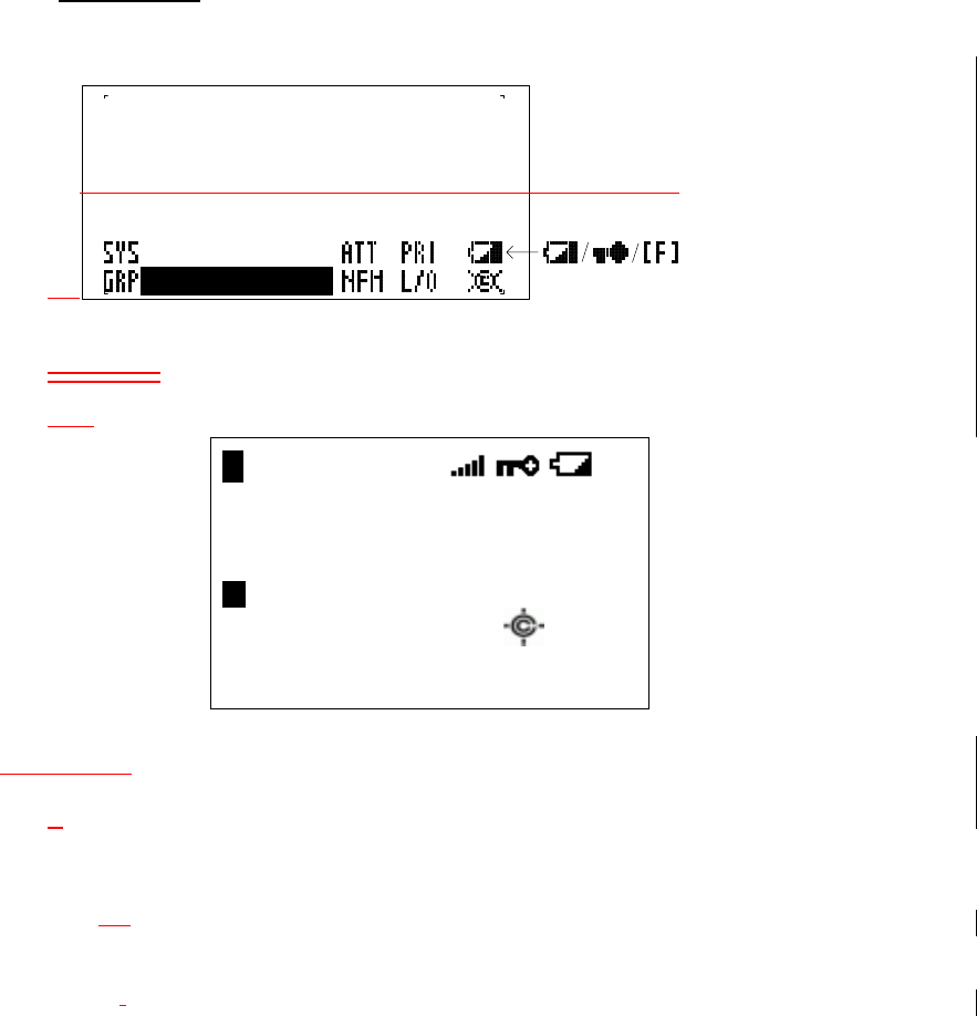
4.2.ICONS
SYS
F HOLD L/O PRI
P WFM ATT P25
S 0 : 1 2 3 4 5 6 7 8 9 0
G R P 1 2 3 4 5 6 7 8 9 0 WX
4.2. ICONS
Sx: :
This icon appears with icons of Quick Key number for Systems ( from “0” to “99”).
x shows current ten’s place of Quick Key for System.
GRPRP :
This icon appears with icons of Quick Key number for Groups (1 - 9,0).
1 - 9, 0 :
In SCAN mode, the numbers of unlocked Quick Key for Systems/Group are
displayed. And a current scanning number blinks.
In SCAN HOLD mode, the Quick Key number of the current System/Group is
displayed.
The numbers of selected User Ranges appear while Custom Search. And the
number of searching Range blinks.
HOLD:
This icon appears in Scan Hold Mode, Search Hold Mode and Close Call Hold Mode.

DSKP:
This icon appears when the Data Skip function is On
Then, this shows in the same place as "HOLD" icon.
L/O :
This icon appears at locked out Channel or frequency.
PRI :
This icon turns on while the Priority Scan works and this blinks while Priority Plus
works.
AM FM NFM WFM:
These icons show the modulation type. "AM", "FM" ,"NFM" or “WFM” will appear.
ATT :
This icon appears when it is set to Attenuator On at the displayed channel.
P25:
This icon shows the digitalized voice of received APCO P25.
LNK :
This icon appears when data on VOICE CHANNEL is received.
Then, this shows in the same place as "P25" icon.
WX :
This icon turns on while the Weather Alert Priority Scan works.
(Function Key) :
This icon appears while pressing Function key.
(Priority Channel) :
This icon appears when channel set to “Priority On".
(Signal Indicator):
This icon shows strength of the signal from 0 to 5.
(KEYPAD LOCK):
This icon will appear only when the KEYLOCK function is On.
(BATTERY Low Alert) :
This icon blinks when the battery voltage is low.
This icon blinks when a bad battery is installed and an AC adopter is connected.
This icon appears during checking the battery.
(Close Call ) :
This icon indicates when the Close Call Mode sets to On, and this blinks while
Close Call Only Mode or when the scanner detects the Close Call.
GPS

Appears when the GPS functionality is enabled by the user.
4.3. DOT MATRIX
128 x 64 Full Dot Matrix
There is a character pattern of 8 x 16 dot and 8 x 8 dot.
See
エラー
!
参照元が見つかりません。
.
エラー
!
参照元が見つかりません。
about
Characters pattern.
4.4. LCD FLASHING TIME
About 500 ms ON / About 500 ms OFF (nearly 1.0 Hz)
4.5. ALERT Indicator
Flashes with a channel alert or location alert.
4.6. Close Call indicator
Flashes when a Close Call hit is detected
SCANNER CONNECTORS
5.1 Front Panel Serial
Standard serial port using Uniden serial jack design.
5.2 Back Panel Serial
Standard DB9 serial port
5.3 Back Panel Power
3-wire power jack for +12V/GND/Headlight Sensor
5.4 TAPE OUT JACK
Jack for tape-out functions.
5.5 EXT SP Jack
External speaker jack
5.6 ANT Jack
BNC Antenna Jack