Uniden America UP689 1.9 GHz UPCS Cordless Telephone - Base Unit User Manual
Uniden America Corporation 1.9 GHz UPCS Cordless Telephone - Base Unit Users Manual
Users Manual

User Operation Specification
Cordless Phone for PBX
DTZ-8R-1
Ver 0.02
APRVD CHECKED(E) CHECKED(S) CHECKED(M) ISSUED
Copyright 2014 Uniden. All rights reserved.
1
Table of Contents
1. Overview____________________________________________________ 5
1.1 Introduction ___________________________________________________ 5
1.2 Digital interface mode ___________________________________________ 5
2. Features ____________________________________________________ 6
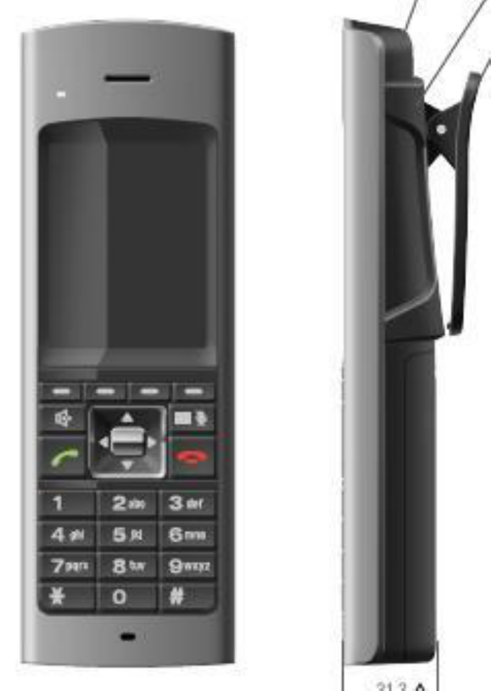
2.1 Handset _______________________________________________________ 8
2.2 Base Station ___________________________________________________ 9
2.3 Charge unit ___________________________________________________ 10
2.4 Key & SW ____________________________________________________ 11
2.4.1 Handset _____________________________________________________ 11
2.4.2 Base ________________________________________________________ 11
2.4.3 Charger ______________________________________________________ 11
2.5 Tone Type and Volume _________________________________________ 12
2.5.1 Frequency definition ___________________________________________ 12
2.5.2 Handset tone types ____________________________________________ 12
2.5.3 Handset volume _______________________________________________ 13
2.5.4 Ring cadence _________________________________________________ 14
2.5.5 Base Station tone _____________________________________________ 15
2.5.6 Charger ______________________________________________________ 15
2.6 Display ______________________________________________________ 16
2.6.1 Handset LCD display __________________________________________ 16
2.6.1.1 Message from PBX Expansion board ________________________________ 17
2.6.2 Handset LCD Icons ____________________________________________ 18
2.6.3 Handset LED _________________________________________________ 19
2.6.4 Base LED ____________________________________________________ 21
2.6.5 Charger LED _________________________________________________ 21
3. Operation & Setup ___________________________________________ 22
3.1 Power Up ____________________________________________________ 22
3.1.1 Handset _____________________________________________________ 22
3.1.2 Base Station __________________________________________________ 22
3.2 Power Down __________________________________________________ 22
3.2.1 Handset _____________________________________________________ 22
3.2.2 Base ________________________________________________________ 22
3.3 Communication to the PBX ______________________________________ 23
3.3.1 Serial interface ________________________________________________ 23
3.3.2 Local operation _______________________________________________ 23
3.3.3 PBX command from the Base Station to PBX Expansion board _______ 24
3.3.4 PBX command from PBX Expansion board to the Base Station _______ 25
3.4 NEC PBX operation ____________________________________________ 26
3.4.1 Change wired phone and cordless phone (DTL-8R-1 Handset) ________ 26
3.4.2 Making call to other Expansion __________________________________ 26
3.4.3 Receiving a Call from other Expansion ____________________________ 29
2
3.4.4 Making call to outside line ______________________________________ 30
3.4.5 Receiving a Call from outside line (Depend on PBX line) _____________ 31
3.4.6 Finish Talk Mode ______________________________________________ 32
3.4.7 Training mode (entry) __________________________________________ 33
3.4.8 Training mode (Next (Softkey 1)key: select item) ___________________ 33
3.4.9 Training mode (Func(Softkey2) key: change each item setting) _______ 33
3.4.10 Training mode (0 key: no function) _______________________________ 33
3.4.11 Training mode (Exit(softkey 4) key: exit from the Training mode) _____ 34
3.5 REDIAL (Option) _______________________________________________ 34
3.6 Channel change _______________________________________________ 35
3.7 Auto Stand-by _________________________________________________ 35
3.8 PBX No Service _______________________________________________ 35
3.9 Out Of Range _________________________________________________ 36
3.10 Low Battery _________________________________________________ 37
3.10.1 Battery status ________________________________________________ 37
3.11 Mute _______________________________________________________ 37
3.12 Hands Free _________________________________________________ 37
3.13 Headset ____________________________________________________ 37
3.14 Volume setting ______________________________________________ 38
3.15 Ring Volume Setting _________________________________________ 39
3.15.1 Ringer volume selection ________________________________________ 39
3.16 Menu setting mode ___________________________________________ 40
3.16.1 Menu Top ____________________________________________________ 40
3.16.2 Contacts(List) ________________________________________________ 41
3.16.3 Contacts(show one by one) _____________________________________ 41
3.16.4 Contacts(Delete Contact) _______________________________________ 42
3.16.5 Contacts(Edit/Add) ____________________________________________ 42
3.16.6 Settings(List) _________________________________________________ 44
3.16.7 Settings(Menu Timeout) ________________________________________ 44
3.16.8 Settings(Brightness) ___________________________________________ 44
3.16.9 Settings(Power Save) __________________________________________ 45
3.16.10 Settings(Audio Equalizer) _____________________________________ 45
3.16.11 Settings(Key Lock) __________________________________________ 46
3.16.12 Sounds(List) ________________________________________________ 46
3.16.13 Sounds(Ring Tones) _________________________________________ 47
3.16.14 Sounds(Vibrate) _____________________________________________ 47
3.16.15 Sounds(Out Of Range Alert) ___________________________________ 48
3.16.16 Sounds(Key Tone) ___________________________________________ 48
3.16.17 Language __________________________________________________ 49
3.16.18 Administrator Setting (List) ___________________________________ 49
3.16.19 Administrator Setting (Registration) ____________________________ 50
3.16.20 Administrator Setting (De-Registration) _________________________ 51
3.16.21 Administrator Setting (Change PIN code) ________________________ 52
3.16.22 Administrator Setting (Site Survey) _____________________________ 53
3.16.23 Administrator Setting (Site Survey:Sync Display mode) ____________ 54
3.16.24 Function Key Label __________________________________________ 54
3
3.16.25 Function Key Label(Name Edit) ________________________________ 55
3.16.26 Function Key Label(Delete Label) ______________________________ 55
3.17 Key Lock ___________________________________________________ 56
3.18 Virtual Function Key __________________________________________ 56
3.19 Base Key Option (Option) T.B.D ________________________________ 56
3.20 Speed Dial Settings (Option) T.B.D _____________________________ 57
4. Appendix __________________________________________________ 58
4.1 Data Table ____________________________________________________ 58
4.1.1 Factory Setting _______________________________________________ 58
4.1.2 Timings ______________________________________________________ 58

4
Revision History
Ver
Issue Date
Originator Description
0.01 April 30,
2014
Shitara 1
st
Edition for NEC. This document is referred
EXP10000 operation specification Rev. 1.1.
0.02 June 06,
2014
Shitara <Change Key assignment>
menu àmenu/mute
mute à speaker
speaker à end
<Add> Base key option ,Speed Dial option
5
1. Overview
1.1 Introduction
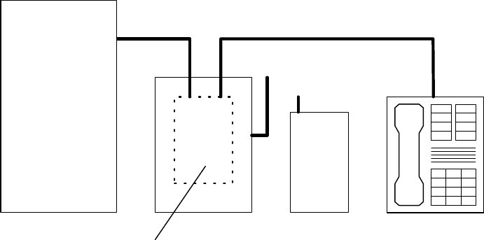
DTL-8R-1 is the cordless phone that is adapted for digital PBX (Private Branch Exchange). It
is usually used in the office environment. When this phone is connected to the digital PBX, it
must have a digital PBX Expansion board inside the Base Station.
PBX
Expansion
Board
Private
Branch
Exchange
(PBX)
Wired Phone
Base Handset
<Notes>
1) Handset and wired phone cannot be used at the same time.
2) Some digital PBX Expansion boards require the wired phone to make a call.
3) Handset and Base Station must have original ID that is written on each unit at factory.
1.2 Digital interface mode
When digital PBX Expansion board is attached to the Base Station, DTL-8R-1 works as
digital mode. Each digital PBX maker will provide the digital PBX Expansion board.
In this mode, the Handset will transmit key press information, which will be sent to PBX by
the Base Station via serial interface.
The Base Station receives PBX command from the digital PBX Expansion board such as
LED state, LCD message, Ringer state, and Talk path condition and transmit them to the
Handset.

6
2. Features
DTZ-8R-1
General
Frequency
1.9G (1920 - 1930MHz)
Audio Process
Digital (ADPCM)
Transmission TDMA/TDD
Number of Channels
5
ID No.
About 130K combinations or more
WiFi Friendly Yes
Number of RF Slot 12(6)
Handset Expandability
No/Yes (Option)
Compatibility w/ other models No
Multi Base No
Multi Repeater
Yes, up to 6
Conference
at same expansion number No/Yes(Option)
HS-HS Intercom/Room Monitor
at same expansion number
No
HS-HS Transfer Call
at same extension number
No
Direct Link (Walkie Talkie)
No
Talk Time
16 hours
Standby Time 7 days
Remote Base & Separate Charger Yes
Wall Mountable
RoHS
Yes
Analog Mode No
(We will develop new analog interface board next stage)
PBX
Interface
Analog PBX Expansion Board No
Repeater Base connection
the Base can handle 2 repeaters with each 2 simultanious calls.
Handset connection Each repeater can handle 2 simultanious calls.
Daisy Chain
3
Base Page No
Base Switch Yes(Left, Right)
LED 3
Power LED
Base Left LED
Base Right LED
Feature
7
DTL-8R-1
Handset Key
29
Programmable Key (API)
12
LCD Display 2 x 24
(10&16 digit mode adjustable)
Standby Display Depend on Interface Board.
There are no Display timeout and LED timeout on the Handset
Line Status Display
No
Display Language
Only English
Icon Talk Icon
Battery Status Icon (3level)
Ringer Off Icon
Message Icon
Hands Free Icon
Mute Icon
LCD Back Light LED
Yes (White)
Key Back Light LED
Yes (Orange)
New Message LED
No
LED
Function key LED×8 (Red)
Hands Free
Yes
Power Off Key
No
Keypad Lock
No
Phonebook
No
One Touch Dial Yes, up to 4 (option)
(Number 24digits/No Name)
Redial Yes (Depend on I/F Board)
(Local mode, 32digits)
F8 key is redial if Interface board does not have this function.
CID
No
Bell in AutoTalk (charge off)
Yes(Always On)
Any Key Answer
Yes((Always On, Dial 0-9, *, #)
Ear Volume Control 6 steps (default: 4)
hearing aid compatible
Handsfree Volume Control
6 steps (default: 4)
Headset Volume Control
6 steps (default: 4)
Ringer Volume High/Low/Off(Vibrate) (default:High)
changed in Standby & Bell Mode
Ringer Tone 6Kinds (default:Tone A)
Tone A, Tone B, Tone C, Tone D, Tone E, Tone F
Vibrating Ringer
Yes
Out of Range Detection
Yes
Out of Range Alarm Tone Yes (On/Off)
(default:On)
Mute
Yes
Auto Standby (Charge On)
Yes
Channel Change
Auto
Ringer Mute Yes
changed in Standby & Bell Mode
On Hook Menu Change Ringer Type
End of Range Alarm
Register(Option)
Deregister(Option)
Base Registration PIN (Option)
One Touch Dial Settings (Option)
Exit
Off Hook Menu
-
Headset Jack
Yes
Feature
8
Display Elements
<Notes>
1) This image differs from the actual design.
2.1 Handset

9
2.2 Base Station
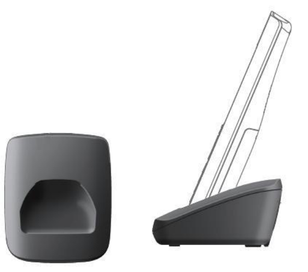
10
2.3 Charge unit
11
2.4 Key & SW
2.4.1 Handset
talk key
speaker key
menu/mute key
end key
up key
down key
right key
left key
select key(center of navigation keys)
dial (0~9、Ú、#) key
Softkey (1~4)key
<Notes>
1) If redial option is enable, Softkey4 key is used for redial key in Talk state.
2) If base key option enable, Softkey1 key is used for Base Left key in Function key
state.
3) If base key option enable, Softkey2 key is used for Base Right key in Function key
state
2.4.2 Base
Left key
Right key
2.4.3 Charger
Charger doesn’t have any key.
12
2.5 Tone Type and Volume
2.5.1 Frequency definition
A
3142Hz
G
2000Hz
M
1046Hz
S
494Hz
B
2637Hz
H
1900Hz
N
1000Hz
T
490Hz
C
2400Hz
I
1800Hz
O
831Hz U
480Hz
D
2346Hz
J
1600Hz
P
800Hz V
430Hz
E
2200Hz
K
1566Hz
Q
700Hz W
400Hz
F
2095Hz
L
1100Hz
R
500Hz
2.5.2 Handset tone types
<Notes>
1) Bell Tone A-F depends on ring cadence from PBX Expansion board.
Bell Tone A K D Repeated Infinitely
48ms 48ms
Bell Tone B O M Repeated Infinitely
24ms 24ms 24ms
Bell Tone C F B A Repeated Infinitely
48ms 48ms 48ms
Bell Tone D N J G Repeated Infinitely
36ms 36ms 36ms
Bell Tone E Q J P Repeated Infinitely
54ms 54ms 54ms
Bell Tone F L J Repeated Infinitely
36ms 36ms
Key Touch Tone G
50ms
Beep Tone S
150ms
Range Alarm Tone N N N
50ms 50ms 50ms 50ms 50ms
Low Battery Alert Tone N
100ms
Error Tone R T U V W
50ms 50ms 50ms 50ms 50ms
Confirmation Tone I H G E C
50ms 50ms 50ms 50ms 50ms

13
2.5.3 Handset volume
Volumes for each tone are shown below.
Tone Type Level Comment
Key Touch Tone LOW -
Error Tone
HIGH
-
Confirmation Tone
HIGH
-
Battery
Low Alert Tone
LOW
Used to warning for battery low
Range Alarm Tone
LOW
Used to warning for out of RF link range
Beep Tone LOW The PBX Expansion board requires this tone
Bell Tone A-F HIGH/MID/LOW/OFF
It depends on Ringer Volume Setting.

14
2.5.4 Ring cadence
When the PBX Expansion board send ring state command to the Base Station, it will be
transmitted to the Handset and the Handset generates bell tone according to the cadence,
which is given by PBX Expansion board.
Cadence 1
2sec
4sec
off
on
Cadence 2
1sec
1sec
off
on 1sec
3sec
Cadence 3
400ms
off
on 800ms
4sec200ms
400ms
200ms
Cadence 4
1sec
2sec
off
on 2sec
4sec
Cadence 5
200ms
100ms
off
on 600ms
4sec
200ms
100ms
<Notes>
1) When ringer volume is Off(Vibrate), Handset vibrates according to this timing(1.5s
on/1s off) in all the cadences.
15
2.5.5 Base Station tone
The Base Station doesn’t have any tone features
2.5.6 Charger
The charger doesn’t have any tone features
16
2.6 Display
2.6.1 Handset LCD display
240 x 320 QVGA LCD
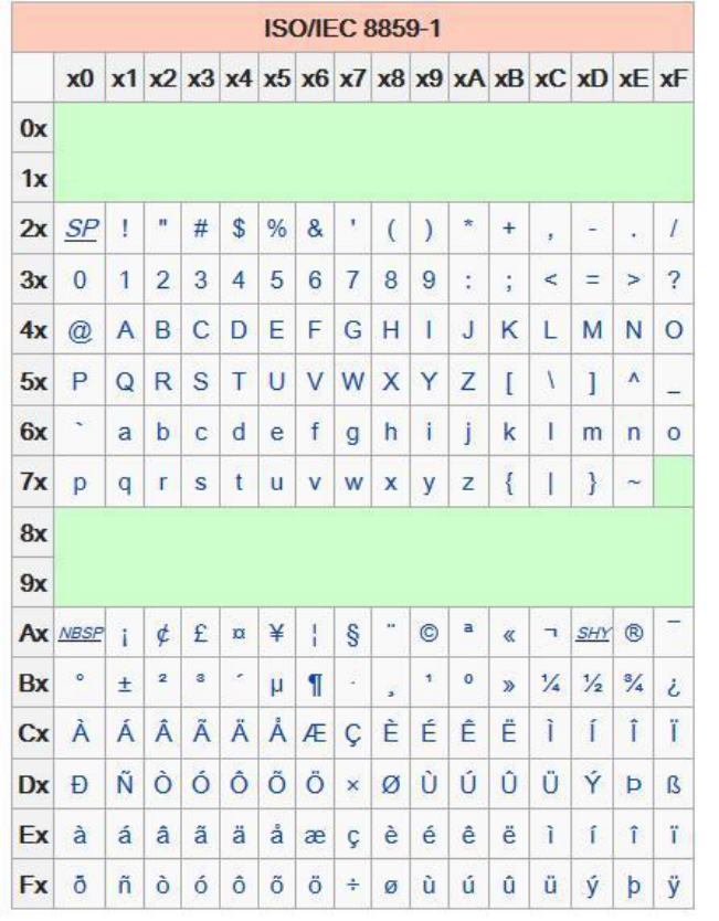
Character code set:ISO/IEC 8859-1(Latin-1)
17
2.6.1.1 Message from PBX Expansion board
When the Handset receives message from PBX Expansion board. Message is shown
according to the followings.
1. LCD is selectable 24x2line(48digits), 16x2line(32digits) or 10x2line(20digits), which is,
determined when ID is written at factory.
2. Message shall be shown with word wrapping (48digits, 32digits or 20digits).
3. If Handset can not show word wrapping digits on one page because of word wrapping,
then message shall be divided into 2 pages
4. If message is shown on 2 pages, each page shall be automatically swap 2.5seconds
periodically.
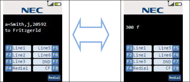
e.g. Show “a=Smith, j, 20592 to Fritzgerrald 300 f”
2.5 seconds
Message shall be erased when:
1. New message is arrived
2. The user presses valid key
3. PBX Expansion board send Clear LCD command.
<Notes>
1) LCD is no timeout to clear the display. It is depend on the PBX Expansion board.
18
2.6.2 Handset LCD Icons
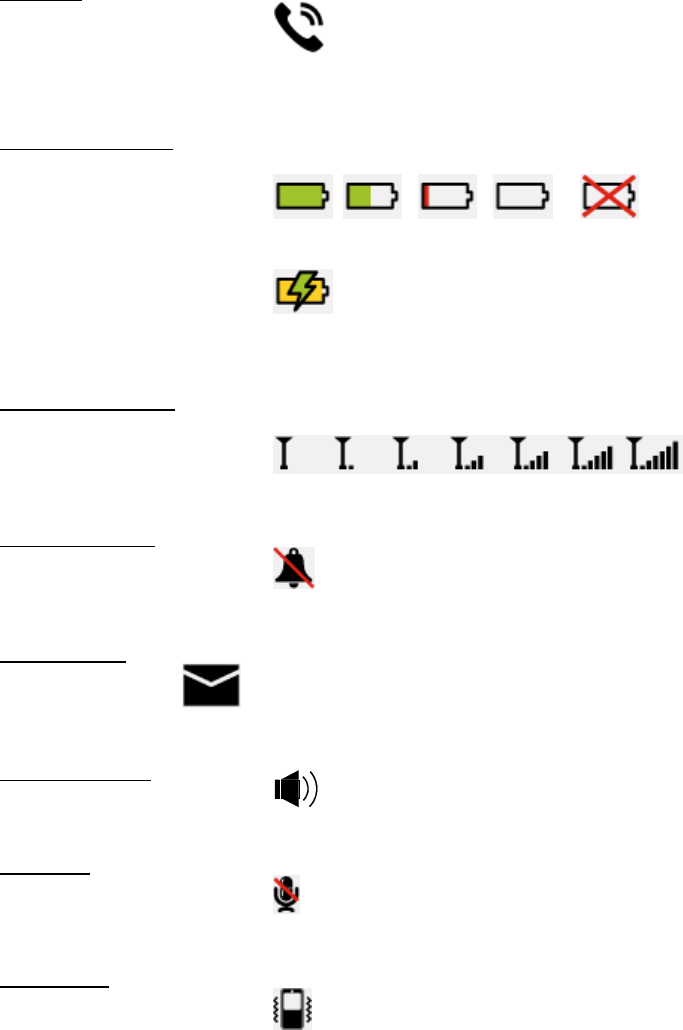
Talk icon
l Handset Talk mode
l Other situation off
Battery Status Icon
l Battery Level
(full) (Level2) (Level1) (Low) (Warning)
l Charge On
<Notes>
1) When you get on the charger with battery full, battery status icon shows battery full.
Antenna Level Icon
l Antenna Level
Level 0 1 2 3 4 5 6
Ringer mute icon
l Ringer mute is on
l Ringer mute is off off
Message icon
l Message exists
l Message doesn’t exist off
Hands Free Icon
l Hands Free Talk
l Ear Speaker Talk off
Mute Icon
l Mute On
l Mute Off off
Vibrate Icon
l Vibrate On
l Vibrate Off off

19
2.6.3 Handset LED
1. Charge LED
ON: On Cradle (charging)
OFF: Off Cradle (not charging)
2. Virtual Function LEDs
All Function LEDs are controlled by PBX according to the PBX command the Base Station
will set each LED to one of cadences bellow.
OFF
Always off
ON
Always on
Blinking 1
500ms
500ms Repeated Infinitely
off
on
Blinking 2
50ms
50ms Repeated Infinitely
off
on
Blinking 3
50ms
Repeated Infinitely
off
on
50ms 500ms
Blinking 4
350ms
50ms
Repeated Infinitely
off
on
<Notes>
1) All Function LEDs will be turned off if the Handset Keeps Standby mode and doesn’t
receive PBX command for about 5 minutes.
20
2) When the Handset is on charge, all Function LEDs will keep status even if it matches
above condition.
3) If the user presses any key (include no valid key) or the user pick up the Handset from
cradle or the user puts the Handset on cradle, LCD/Key Back Light is turned on.
LCD/Key Back Light will be turned off after 10 seconds When no operation.
4) LCD/Key Back Light is turned on during incoming call mode.

21
2.6.4 Base LED
Power LED
l Base is powered on on
l Base is powered off off
l Registration mode blink
Base Left LED
Controlled by the PBX Expansion board.
Base Right LED
Controlled by the PBX Expansion board.
2.6.5 Charger LED
There is no LED on charger.
22
3. Operation & Setup
In the following description, the key touch-tone will be emitted when a valid key is pressed.
3.1 Power Up
3.1.1 Handset
When the battery is put into the Handset, it will start operation.
At the very beginning, the Handset reads some setting from EEPROM and the Handset
starts operation.
Also the Handset reads ID from EEPROM and will use it for RF communication between it
and the Base Station.
3.1.2 Base Station
It will start operation after Install the AC adapter into rear of the Base Station.
At the very beginning, the Base Station reads ID from EEPROM and will use it for RF
communication between it and the Handset.
3.2 Power Down
3.2.1 Handset
If the Handset loses battery or the battery level decreases more than a threshold that is in
EEPROM, it goes to power down mode.
Even if the Handset power is reinstated immediately after it is lost during Talk mode, the
Handset will not return to Talk mode.
(DTL-8R-1 does not support talk back function.)
3.2.2 Base
Even if the Base power is reinstated immediately after it is lost during Talk mode, the
Handset will go Standby mode. (Not supports talk back function.)
23
3.3 Communication to the PBX
3.3.1 Serial interface
Serial communication between PBX Expansion board and the Base Station is performed by
UART (Universal Asynchronous Receive and Transmit) with 2400bps speed.
3.3.2 Local operation
These operations are independent from the PBX Expansion board control.
It is performed by the DTL-8R-1 itself.
1. Key press detection and emit key touch tone
2. RF link establishment
3. Show “ACQUIRING LINK”
4. Ringer volume setting
5. Switching Ear speaker and Hands free speaker
6. Ear speaker volume, Hands free volume and Headset volume change
7. Dial echo back on LCD
8. Mute
9. Redial (option)
10. Battery Status Icon change (Battery low detection)
11. Menu operation
12. Ring mute operation
13. One Touch Dial (option)
14. Headset operation
15. Contact List operation

24
3.3.3 PBX command from the Base Station to PBX Expansion board
Value
(Hex) Additional
Data Command Name Explanation
81 Button ID
(1byte) Button press Function (F1-F12) or dial (0-9, *, #)
button is pressed
82 Button ID
(1byte) Button release Function (F1-F12) or dial (0-9, *, #)
button is released
83
--
Talk button press
Talk button is pressed
84 -- Training mode on Notification for entry to training mode
(Press and hold */# button then press
Talk
button)
85 -- Training mode off Notification for exit from training mode
(Press talk button during training mode)
86 EEPROM data
(32bytes)
Contents of Base
Station EEPROM
The Data from EEPROM when PBX
requests to read.
87
--
Base sw1 press
Base
Left
key is pressed
88 -- Base sw2 press Base Right key is pressed
89 -- Skip forward Skip forward request in training mode
(up key is pressed)
8A -- Skip backward Skip backward request in training mode
(down key is pressed)
8B -- Clr/Dflt entry Clear/Default request in training mode
(Dial 0 key is pressed)
Button ID
0 0x00
1 0x01
2 0x02
3 0x03
4 0x04
5 0x05
6 0x06
7 0x07
8 0x08
9 0x09
* 0x0A
# 0x0B
F1 0x0C
F2 0x0D
F3 0x0E
F4 0x0F
F5 0x10
F6 0x11
F7 0x12
F8 0x13
F9 0x14
F10 0x15
F11 0x16
F12 0x17

25
3.3.4 PBX command from PBX Expansion board to the Base Station
Value
(Hex) Additional
Data Command Name Explanation
81 -- Enable DTMF If the Base Station receives this
command send DTMF signal while dial
button is pressed.
82 LED ID (1byte)
LED State (1byte) Change LED
state When the Base Station receives this
command change LED state according
to LED ID and LED State.
83 or
84 -- Clear LCD When the Base Station receives this
command clear current message on
the LCD
85 or
86 Number of
characters (1byte)
Char1-CharN
LCD Character The Handset shows this LCD character
N = 96
87
Ring state
(1byte)
Change ring state
The Handset change ring state
88 -- Read EEPROM Read EEPROM request from PBX
Expansion board
89 Data (32bytes) Write EEPROM Write EEPROM request from PBX
Expansion board
8A -- Clear all state Clear all current status in the Handset
and Base Station and goes back to
standby mode
8B
--
Talk path enable
Open audio path
8C -- Talk path disable Close audio path
8D or
8E Tx Gain (1byte)
Rx Gain (1byte) Offset Audio
Level Control the AFE Tx/Rx Gain
LED ID
F1 LED 0x0C
F2 LED 0x0D
F3 LED 0x0E
F4 LED 0x0F
Transfer 0x10
Message 0x11
Base Right LED 0x12
Base Left LED 0x13
F9 LED 0x14
F10 LED 0x15
F11 LED 0x16
F12 LED 0x17
<Notes>
1) Transfer and Message ID can be controlled Icon on LCD, not LED. Transfer ID is for
Talk Icon. Message ID for Message Icon
2) Talk Icon can be controlled during only Talk Mode
26
3.4 NEC PBX operation
This operation is one of examples for the DTL-8R-1 with NEC PBX. So it might be different
from actual operation in detail. Operation of DTL-8R-1 in digital mode depends on each PBX
specification.
3.4.1 Change wired phone and cordless phone (DTZ-8R-1 Handset)
Press Base Left key to change to cordless phone (DTZ-8R-1 Handset) and press Base Right
key to change to wired phone. The LCD shows this messages.
Base Left key Base Right Key
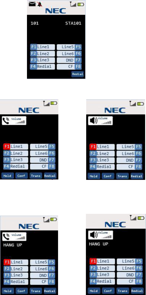
3.4.2 Making call to other Expansion
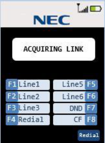
Step 1 Press the talk key on the Handset. The Handset will try to connect to the Base
Station while “ACQUIRING LINK” message appeared.
27
Step 2 When connected, The Handset goes to Talk mode and Talk icon is turned on and
shows current volume.
Talk key Speaker key
Step 3 If the user enters dial 1,2, 3 then LCD shows the dial number pressed as dial echo.
Talk Speaker
Step 4 The LCD shows this message to indicate call is taking place.
Talk Speaker
28
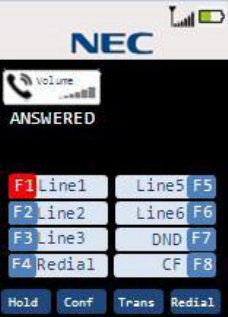
Step 5 When call partner answers call. The LCD shows this message to indicate phone is
in Talk mode.
Talk Speaker
<Notes>
1) When Base Station is not connected to PBX, Handset shows message
“DISCONNECT”.
2) When Handset cannot connect to Base Station, error tone will be emitted and “Out of
Range” message is shown for 5 seconds on the LCD. Then Handset goes to standby
mode.
3) When wired phone is selected, Handset cannot go Talk mode.
29
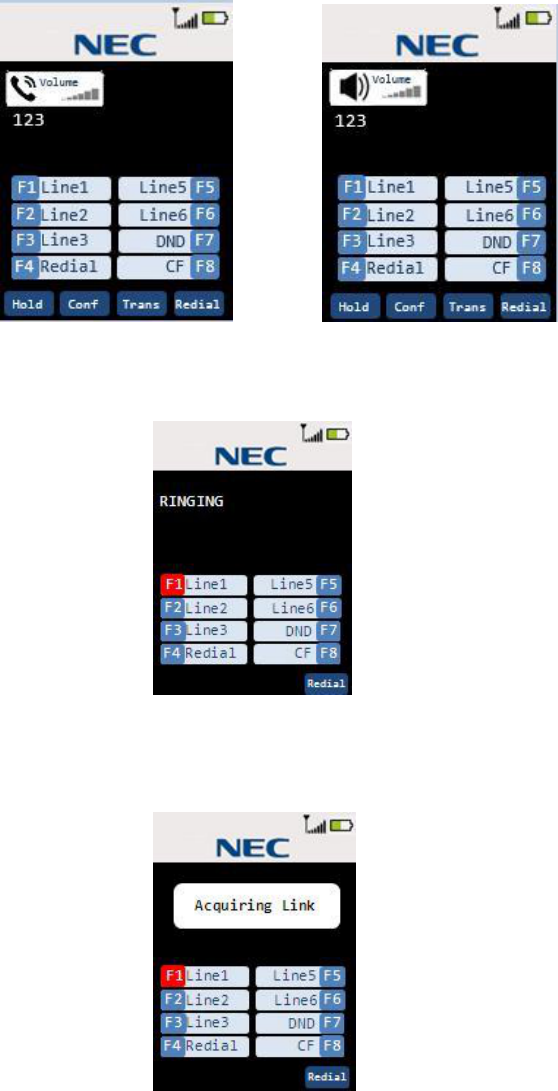
3.4.3 Receiving a Call from other Expansion
Step 1 When incoming call is coming from the Expansion, The Handset goes to Incoming
call Mode and shows this message to indicate Expansion call is coming.
Step 2 If the user presses talk key or dial key (0-9, *, #) or the user picks up the Handset
from cradle, Handset tries to connect Base Station and shows “ACQUIRING LINK”
message appeared. If RF connection is established quickly this message might not
be shown.
Step 3 When connected, Talk icon is turned on and shows current volume.
After the Handset answers Expansion call, it shows this message to indicate
phone is in Talk mode.
Talk Speaker
30
3.4.4 Making call to outside line
Step 1 Press the select key on the Handset and select F1. The Handset starts to
establish RF connection with the Base Station. LCD is not changed.
Step 2 When RF connection is established, the Handset goes to Talk Mode and Talk icon
is turned on and current volume is shown on the LCD. And F1 LED is turned on.
<Notes>
1) When the outside line is not connected with PBX, Handset shows message “HANG
UP” and emits busy tone.
31
Step 3 If the user enters dial 1, 2, 3 then LCD shows the dial number pressed as dial
echo.
Talk Speaker
3.4.5 Receiving a Call from outside line (Depend on PBX line)
Step 1 When incoming call from outside is coming, F1 LED is blinking.
Step 2 If the user presses talk key or dial key (0-9, *, #) or the user picks up the Handset
from cradle, Handset tries to connect Base Station and shows “Acquiring Link”
message appeared. If RF connection is established quickly this message might not
be shown.
<Notes>
1) If F1 key(select key à up/down àselect key) is pressed, Handset tries to connect
Base Station. But “Acquiring Link” message is not shown on the LCD.
32
Step 3 When RF connection is established. The Handset goes to Talk mode and turns on
talk icon and shows current volume.
3.4.6 Finish Talk Mode
The Handset keeps RF link for about 1 second after finish Talk mode.
33
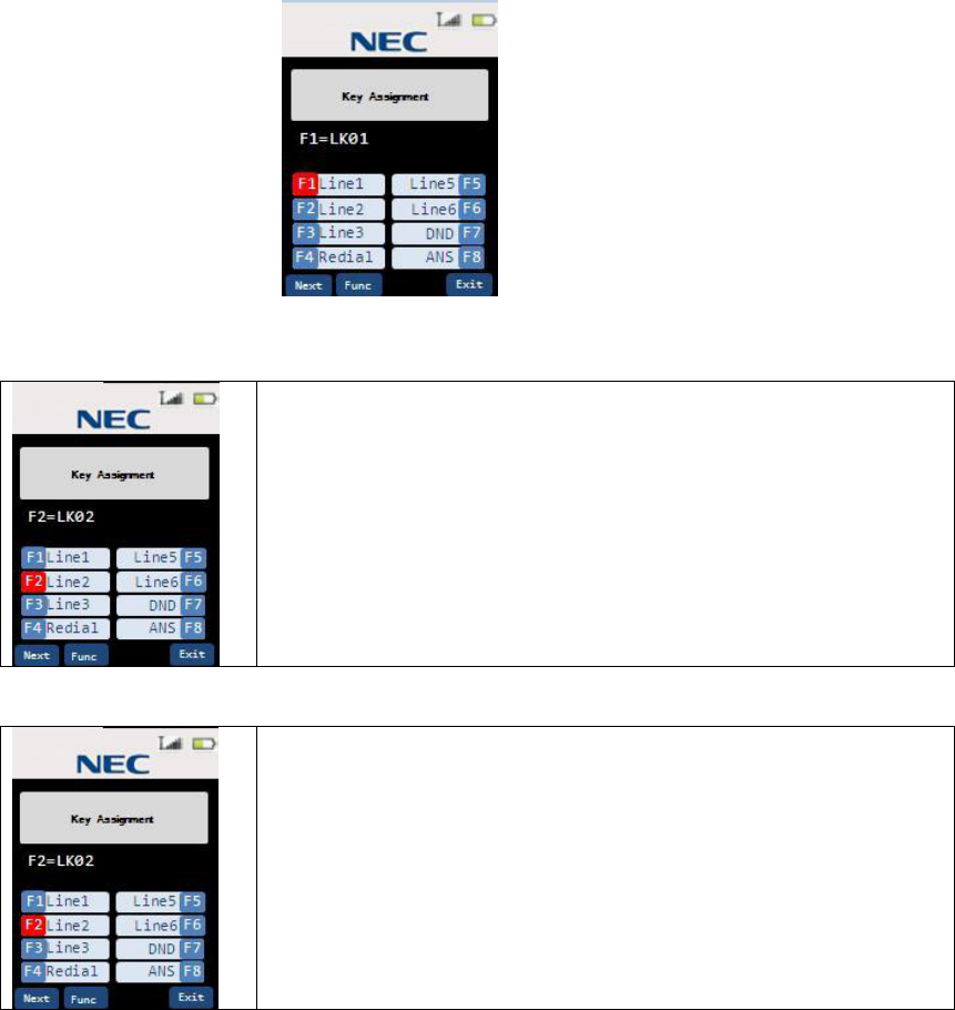
3.4.7 Training mode (entry)
Press * and # at the same time then press talk key. The Handset emits confirmation tone
and enters to training mode. This message is shown on the LCD and F1 LED is blinking.
3.4.8 Training mode (Next (Softkey 1)key: select item)
To select item, press Next key
Item changes as followings.
F1àF1(TALK)àF2àF2(TALK)àF3àF3(TALK)àF4à
àF4(TALK)àF5àF5(TALK)àF6àF6(TALK)àF7à
àF7(TALK)àF8àF8(TALK)àOFF HOOK RINGàF1…
3.4.9 Training mode (Func(Softkey2) key: change each item setting)
To change item setting, press Func key
Item setting changes as followings.
LK01àLK02àLK03àLK04àLK05àLK06àLK07àLK08à
àLK09àLK10àLK11àLK12àLK13àLK14àLK15àLK16à
àLNR/SPDàRecallàFNCàANSàLK01…
3.4.10 Training mode (0 key: no function)
When 0 button is pressed during training mode, key touch tone will be emitted but any
function doesn’t work in case of the NEC PBX.
34
3.4.11 Training mode (Exit(softkey 4) key: exit from the Training mode)
When Exit key is pressed anytime during training mode, key touch-tone will be emitted and
“Training off” command is sent to the PBX Expansion board. The Handset will exit from the
Training mode.
3.5 REDIAL (Option)
When the RF link is established between the Handset and the Base Station and no dial key
operation is performed. If the user presses redial key, the last number dialed will be shown
and these dials will be sent to the Base Station.
<Notes>
1) Error tone will be emitted when redial is empty.
2) Dial limit is 32 digits, so redial will store up to 32 digits in memory.
3) Redial data is stored in Handset memory (EEPROM).
4) If F1-F12 key is pressed the number dialed before Function key is pressed will be
stored in redial memory.
5) redial key is invalid when the Handset outputted dial. This means redial key is valid as
1st dial.
<Example>
(1) [talk][1][2][3][talk] redial: 123
(2) [talk][1][2][3]……….[1][2][talk] (over 32digits) redial: 123……12 (up to 32digits)
(3) [talk][1][2][3][F1][4][5][6][talk] redial: 123
35
3.6 Channel change
It changes channel automatically.
3.7 Auto Stand-by
When the Handset is in these modes, which is shown below placing the Handset on the
Charger will change it to Stand-by mode. At this time, confirmation tone is emitted.
l Ringer volume setting
l Menu setting
l Talk mode
l Trying to connect to the Base Station
3.8 PBX No Service
Talk or speaker key is pressed when the Base Station is using wired phone or there is not
acknowledgment from PBX.
The Handset goes to standby mode after the LCD shows below.
<Notes>
1) Handset does not emit tone, when it goes to standby mode.
36
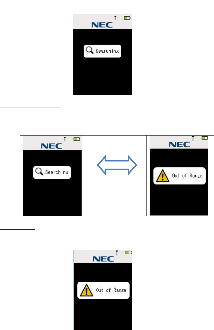
3.9 Out Of Range
When Standby Mode
The Handset shows message “Searching” when the Handset cannot find the Base Station
(Out of Range) in Standby Mode.
When establish RF link
If the talk, speaker key is pressed but the Handset cannot establish RF Link with the Base
Station, Handset will sound error tone and shows message “Out of Range”.
Talk/Speaker
(Back to Searching
screen after 5sec
elapsed)
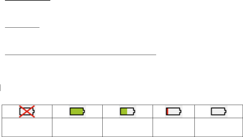
While Talking
If the Handset cannot receive a signal from the base in about 5 seconds, it goes to Standby
mode with an error tone. In this case, the LCD shows message below. If the base cannot
receive a signal from the Handset in about 5 seconds, it goes to Standby mode.
37
3.10 Low Battery
The Handset has visual and audible indicators to warn of low battery condition.
In Standby mode
Battery status Icon in the LCD will change to battery low.
“Charge Battery” message blinks on the LCD (ON: 600msec, OFF: 600msec).
In Talk mode
Battery status Icon in the LCD will change to battery low.
The Handset keeps Talk mode and battery low alert tone will be emitted every 30 seconds.
In Other mode (Excluding Standby mode and Talk Mode)
Battery status Icon in the LCD will change to battery low.
3.10.1 Battery status
The LCD shows it the battery according to the remainder capacity of the battery.
(Warning)
Non Rechargeble
Battery
(Full)
100-67% (Level 3)
66-34% (Level 2)
33-10% (Low)
9-0%
3.11 Mute
Press menu/mute key during Talk mode. Mute icon will be turned on and voice sound from
Microphone will be muted (partner can not hear voice from the user).
Pressing menu/mute key again will cancel mute condition and Mute icon will be turned off.
Finishing Talk mode can also cancel mute condition.
3.12 Hands Free
Press speaker key in standby mode or during Talk mode. Then the Handset goes to Hands
Free Talk mode and Hands Free Icon will be turned on.
Press talk key in Hands Free Talk mode. Then Hands Free icon will be turned off and goes
to Talk Mode. Press speaker key in Hands Free Talk mode. Then The Handset cancels Talk
mode and goes to Standby mode.
3.13 Headset
Insert Headset plug in Headset Jack in Talk mode or Hands Free Talk mode, the Handset
goes to Headset condition.
Pull Headset plug in Headset Jack in Headset condition. Then the Handset goes to original
Mode (Hands Free Talk Mode or Talk mode)
<Notes>
1) In headset condition, the user can change Hands-Free mode to the talk mode. But the
Handset keeps Headset condition.
38
2) Insert Headset plug in Headset Jack when Hands Free condition. Hands Free icon will
be not turned off.
3) Tone is output from speaker when Headset is connected.
3.14 Volume setting
There are 3 volume settings. Talk mode, Hands Free Talk Mode and Headset condition have
each volume.
During each mode if the user presses up or down key, the LCD shows current volume.
During show volume if the user presses up or down key, the volume setting will be changed
from Level 1 to Level 6.
39
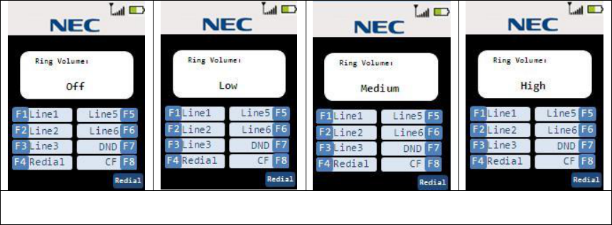
3.15 Ring Volume Setting
3.15.1 Ringer volume selection
Step 1 When up key is pressed in Standby mode, the Handset goes to Ringer volume
setting mode and shows current setting.
The Ring volume will be changed as following.
àUp
ßDown
<Notes>
1) The Handset keeps ringer volume setting mode for 2 seconds without key operation.
2) Handset can change ringer volume in Incoming call mode. In this case the Handset
changes ringer volume.
40
3.16 Menu setting mode
<Notes>
1) Press Exit key or end key in each menu setting mode. Then the Handset goes to
standby mode.
2) The Handset keeps each menu setting mode for a while(depends on Menu timeout
setting) without key operation. The Handset cancel menu setting and goes to Standby
mode with Error tone.
3) Press menu/mute key in each menu setting mode, menu returns upper list.
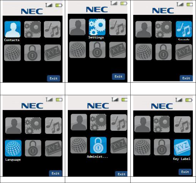
3.16.1 Menu Top
Step 1 Press the menu/mute key in standby mode. Then the LCD shows menu list mode.
Step 2 Select item by up or down /Right /Left key and press select key.
Contact List
Settings
Sounds
Language
Administrator Setting
Function Key Label
41
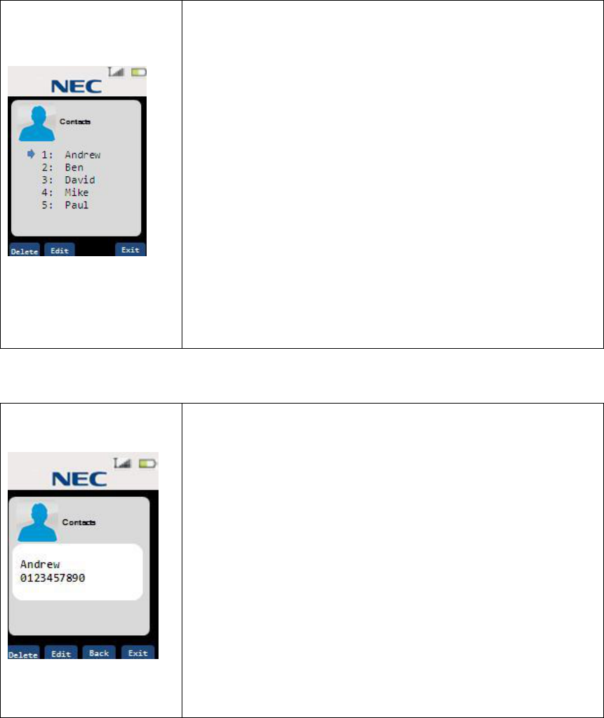
3.16.2 Contacts(List)
Step 1 Press the menu/mute key in standby mode. Then the LCD shows menu list mode.
Step 2 Select “Contacts” and press select key.
In this screen, following keys are available.
<To Select Contact List>
up/down key:
Increment or Decrement Contact List Number.
Left/Right key:
Contact List number +5 or -5. (show next/previous screen)
select key:
Show Detail.(Contact list shows one by one.)
<To Edit Contact List>
Delete key(softkey 1) :
To Delete contents of pointed Contact List Number.
Edit key / Add key (softkey 2) :
To Edit contents of pointed Contact List Number.
If the contents of pointed Contact List is empty,
Softkey indicates “Add”.
<To Dial from Contact List>
Talk/Speaker key:
To Dial Contact List.
3.16.3 Contacts(show one by one)
In this screen, following keys are available.
<To Select Contact List>
up/down key:
Increment or Decrement Contact List Number.
Back key:
Back To List screen.
<To Edit Contact List>
Delete key(softkey 1) :
To Delete contents of pointed Contact List Number.
Edit key / Add key (softkey 2) :
To Edit contents of pointed Contact List Number.
If the contents of pointed Contact List is empty,
Softkey indicates “Add”.
<To Dial from Contact List>
Talk/Speaker key:
To Dial Contact List.
42
3.16.4 Contacts(Delete Contact)
In this screen, following keys are available.
Yes key:
Delete Contact with confirmation tone.
After Delete contents, Back to Previous screen.
No key:
Back To previous screen.
3.16.5 Contacts(Edit/Add)
Step 1 Enter Name for contact.
<Add: Edit New>
<Edit:Rename>
Maximum 8 characters can be stored in each contact.
In this screen, following keys are available.
Back Key: Back to previous screen
Next Key: Go to Number edit screen
123/abc key(toggle)
“123” : To numeric input
“abc” : To alphabetical input
Delete Key
Delete character of cursor position
[Alphabetical input]
Dial Keys
Dial 1 : @.-_&'^?!(),\\/:;~=+1
Dial 2 : abcABC2
Dial 3 : defDEF3
Dial 4 : ghiGHI4
Dial 5 : jklJKL5
Dial 6 : mnoMNO6
Dial 7 : pqrsPQRS7
Dial 8 : tuvTUV8
Dial 9 : wxyzWXYZ9
Dial 0 : 0
Dial * : *
Dial # : #
Right/Left Key(alphabetical Input only)
Cursor moves
Step 2 Enter Number for contact.
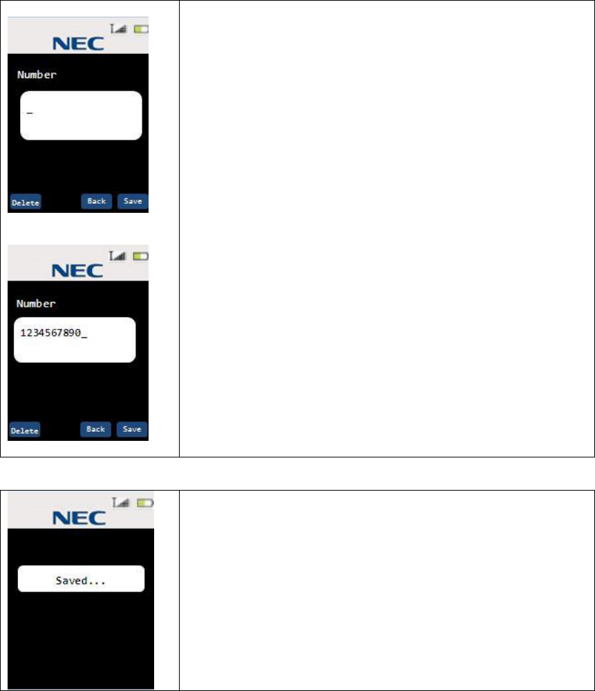
43
<Add: Edit New>
<Edit:change number>
Maximum 24 digits number can be stored in each contact.
16digits can be displayed in 1st line.
Over 16digits, number displayed in 2nd line.
In this screen, following keys are available.
Back Key: Back to previous screen
Next Key: Go to Number edit screen
Delete Key
Delete number of cursor position
Save Key
To store contact with confirmation tone.
Step 3 Saved screen
After 2seconds elapsed, return to Contact list or View(one by
one).
44
3.16.6 Settings(List)
Step 1 Press the menu/mute key in standby mode. Then the LCD shows menu list mode.
Step 2 Select “Settings” and press select key.
In this screen, following keys are available.
up/down key:
Pointer moves
select key:
Select menu item and enter each menu setting
3.16.7 Settings(Menu Timeout)
Step 1 Select “Menu Timeout” and press select key. Then the LCD shows menu timeout
setting screen.
Pointer is pointed to the current timeout value.
(Default value is 30seconds.)
In this screen, following keys are available.
up/down key:
Pointer moves
select key:
Store each value with confirmation tone.
And return to previous(setting list) screen.
3.16.8 Settings(Brightness)
Step 1 Select “Brightness” and press select key. Then the LCD shows Brightness setting
screen.
Pointer is pointed to the current brightness value.
(Default value is MAX.)
MAX=100% HIGH=80% MID=60% LOW=20%
In this screen, following keys are available.
up/down key:
Pointer moves with change LCD backlight brightness.
select key:
Store each value with confirmation tone.
And return to previous (setting list) screen.
45
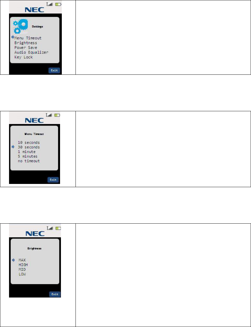
3.16.9 Settings(Power Save)
Step 1 Select “Power save” and press select key. Then the LCD shows Power Save setting
screen.
Pointer is pointed to the current power save value.
(Default value is On.)
On: LCD goes to sleep mode with LCD backlight turn off.
Off: LCD backlight dimly.
<Condition of enter to Power save>
1.1minute elapsed without key operation in Standby or Talk.
<Confition of Exit from Power save>
1. Press any key
2. Receive command from Base Station.
3. Handset charge on / off.
In this screen, following keys are available.
up/down key:
Pointer moves.
select key:
Select each value with confirmation tone.
And return to previous (setting list) screen.
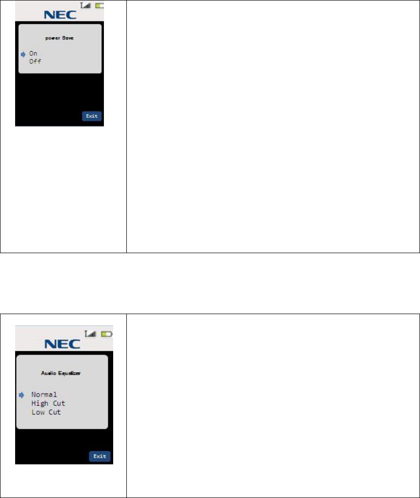
3.16.10 Settings(Audio Equalizer)
Step 1 Select “Audio Equalizer” and press select key. Then the LCD shows Audio Equalizer
setting screen.
Pointer is pointed to the current Audio Equalizer value.
(Default value is Normal.)
Normal: Natural Audio
High Cut: Cut High Frequency
Low Cut: Cut Low Frequency
In this screen, following keys are available.
up/down key:
Pointer moves.
select key:
Select each value with confirmation tone.
And return to previous
(setting list) screen.
46
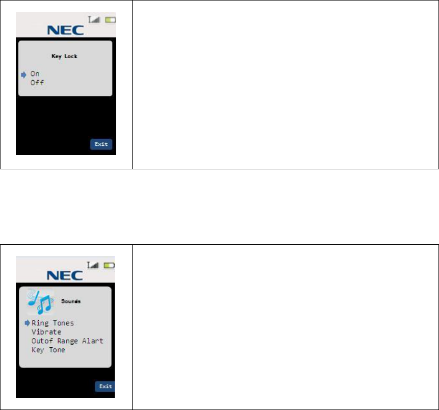
3.16.11 Settings(Key Lock)
Step 1 Select “Key Lock” and press select key. Then the LCD shows Key Lock setting
screen.
Pointer is pointed to the current Key Lock value.
(Default value is Off.)
On: Enable Key Lock Function
Off: Disable Key Lock Function
In this screen, following keys are available.
up/down key:
Pointer moves.
select key:
Select each value with confirmation tone.
And return to previous (setting list) screen.
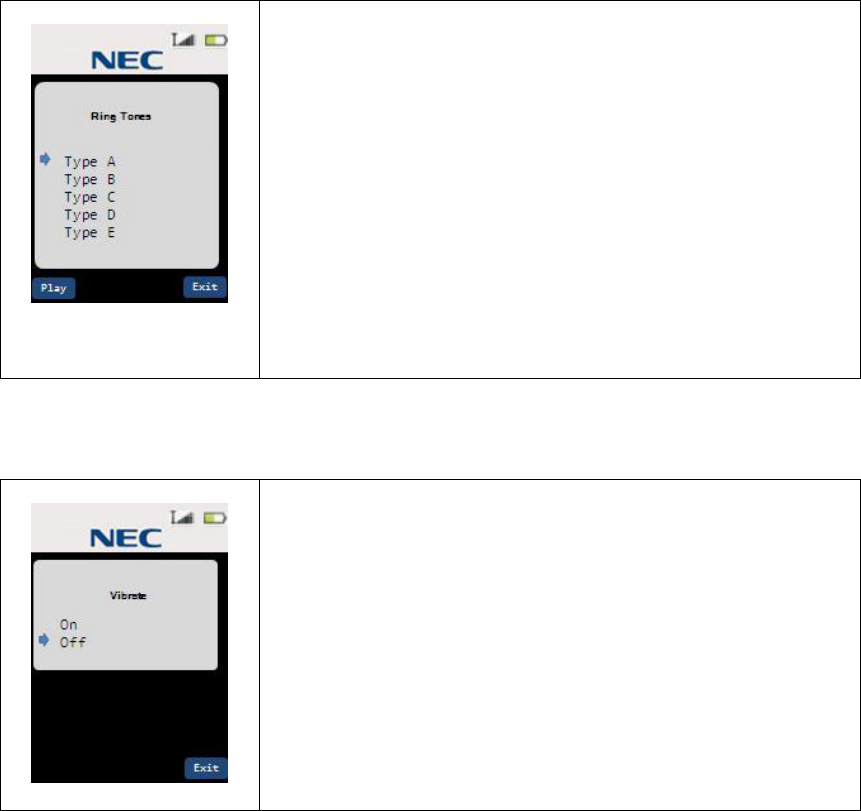
3.16.12 Sounds(List)
Step 1 Press the menu/mute key in standby mode. Then the LCD shows menu list mode.
Step 2 Select “Sounds” and press select key.
In this screen, following keys are available.
up/down key:
Pointer moves
select key:
Select menu item and enter each menu setting
47
3.16.13 Sounds(Ring Tones)
Step 1 Select “Ring Tones” and press select key. Then the LCD shows Ring Tones setting
screen.
Pointer is pointed to the current Ring Tone.
(Default value is Type A.)
There are 6 types Ring tones(Type A – Type F) available.
In this screen, following keys are available.
up/down key:
Pointer moves.
play key:
Play sample ringer tone for 2 seconds.
select key:
Select each value with confirmation tone.
And return to previous (setting list) screen.
3.16.14 Sounds(Vibrate)
Step 1 Select “Vibrate” and press select key. Then the LCD shows Vibrate setting screen.
Pointer is pointed to the current Vibrate setting.
(Default value is On.)
On: Vibrate turns on while Incoming Call
Off: Viberate turns off
In this screen, following keys are available.
up/down key:
Pointer moves.
select key:
Select each value with confirmation tone.
And return to previous (setting list) screen.
48
3.16.15 Sounds(Out Of Range Alert)
Step 1 Select “Out Of Range Alert” and press select key. Then the LCD shows Out Of
Range Alert setting screen.
Pointer is pointed to the current Out Of Range Alert setting.
(Default value is On.)
On: Out Of Range Alert turns on
Off: Out Of Range Alert turns off
In this screen, following keys are available.
up/down key:
Pointer moves.
select key:
Select each value with confirmation tone.
And return to previous (setting list) screen.
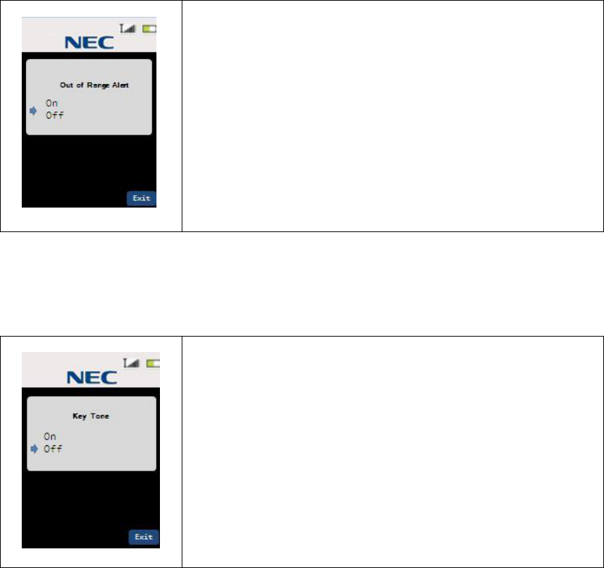
3.16.16 Sounds(Key Tone)
Step 1 Select “Key Tone” and press select key. Then the LCD shows Key Tone setting
screen.
Pointer is pointed to the current Key Tone setting.
(Default value is On.)
On: Enable Key Tone function
Off: Disable Key Tone function
In this screen, following keys are available.
up/down key:
Pointer moves.
select key:
Select each value with confirmation tone(Key tone is On).
And return to previous (setting list) screen.
49
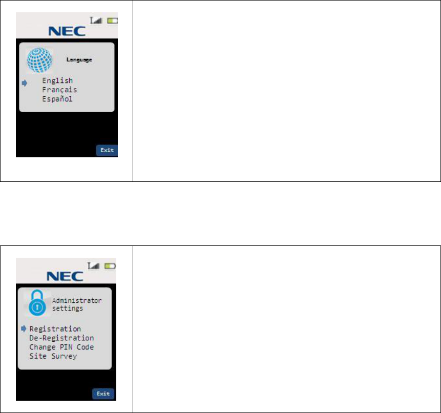
3.16.17 Language
Step 1 Press the menu/mute key in standby mode. Then the LCD shows menu list mode.
Step 2 Select “Language” and press select key.
Pointer is pointed to the current Language setting.
(Default value is English.)
There are 3 languages (English, French, Spanish) available.
In this screen, following keys are available.
up/down key:
Pointer moves
select key:
Select new display language and returns to Menu Top.
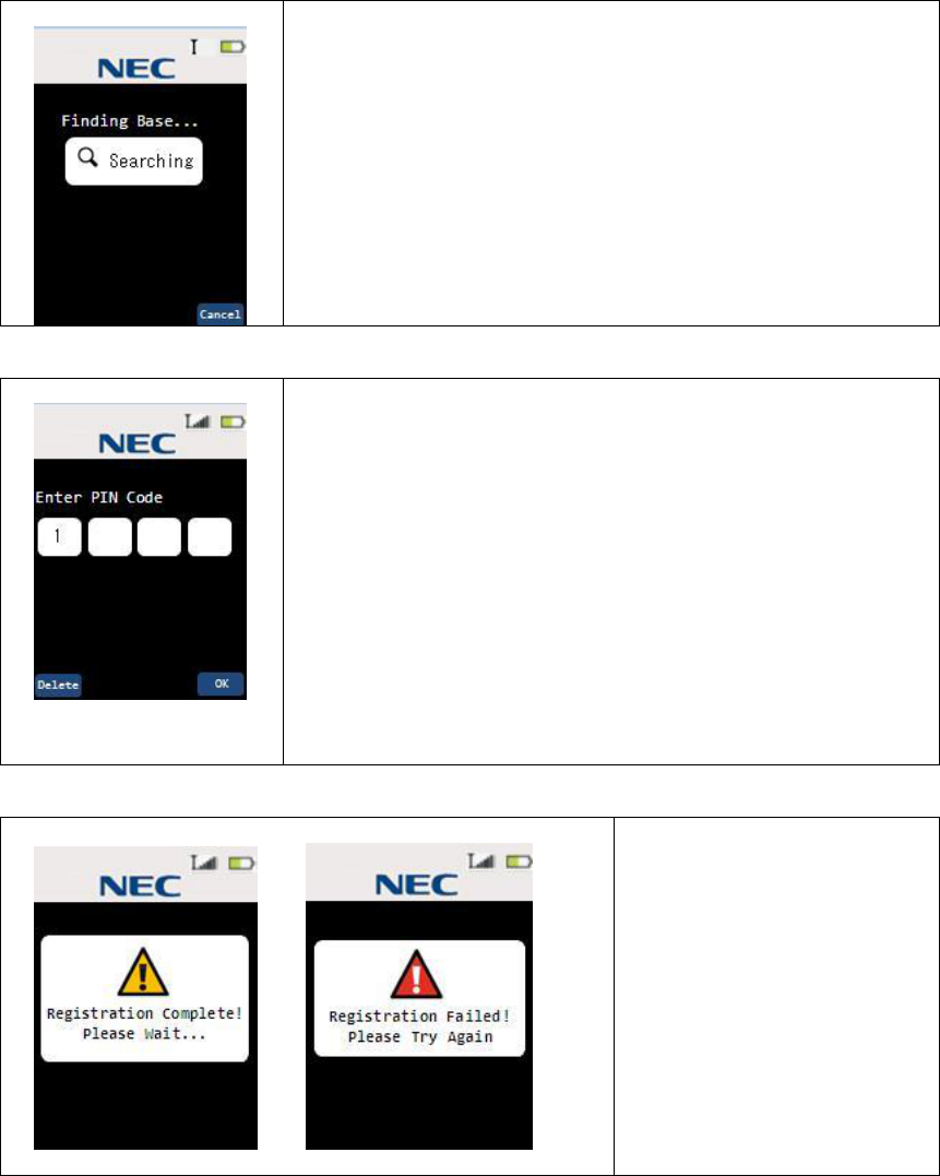
3.16.18 Administrator Setting (List)
Step 3 Press the menu/mute key in standby mode. Then the LCD shows menu list mode.
Step 4 Select “Administ…” and press select key.
In this screen, following keys are available.
up/down key:
Pointer moves
select key:
Select menu item and enter each menu setting
50
3.16.19 Administrator Setting (Registration)
Step 1 Press and Hold Base Station Left Key until Blue LED start blinking. (for 3seconds)
Step 2 Select “Registration” and press select key. Then the LCD shows Registration
screen.
Start finding Base Station.
In this screen, following keys are available.
cancel key:
Exit from registration mode
Step 3 Handset find Base Station.
Enter Registration PIN.
In this screen, following keys are available.
(Default Value is “1234”)
delete key:
Delete 1 digit.
Dial(0-9) key:
Enter 1 digit.
OK key:
Send Registration PIN to the Base Station.
Step 4 Finish Registration.
After 5 seconds elapsed, The
Handset goes to each state.
Registration completed:
goes to Standby state
Registration Failed:
goes to De-register state
or Standby state.
51
3.16.20 Administrator Setting (De-Registration)
Step 1 Select “De-Registration” and press select key. Then the LCD shows De-Registration
screen.
Display Available Handset number(Handset #1 only)
As for Operating Handset, display ”[Using]” next of Handset #.
In this screen, following keys are available.
up/down key:
Pointer moves (If the other handset registered)
select key:
Select pointed handset and goes to confirmation display.
Step 2 To start De-Registration, press Yes Key.
In this screen, following keys are available.
Yes key:
Start De-Registration
No key:
Return to Standby state.
52
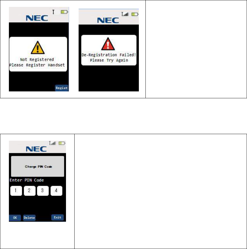
Step 3 Finish De-Registration.
If the De-Registration failed,
The Handset goes to Standby state
after 5 seconds elapsed.
In De-Register screen, following
keys are available.
Regist key:
Start Registration
3.16.21 Administrator Setting (Change PIN code)
Step 1 Select “Change PIN Code” and press select key. Then the LCD shows Change PIN
Code screen.
When enter this setting, the handset start communicating with
Base Station and get current PIN number.
Then, Show current PIN number in this screen.
In this screen, following keys are available.
delete key:
Delete 1 digit.
Dial(0-9) key:
Enter 1 digit.
OK key:
Send New Registration PIN to the Base Station with
confirmation tone sounds.
53
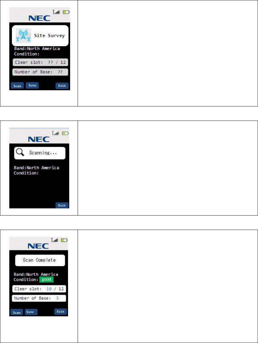
3.16.22 Administrator Setting (Site Survey)
Step 1 Select “Site Survey” and press select key. Then the LCD shows Site Survey screen.
In this screen, includes following contents.
Band: Carrier Band of this Handset. (North America)
Condition: good / Fair / Poor
Clear Slot: number of Clear slot (total number of slot is 12)
Number of Base: Number of Base that handset found.
In this screen, following keys are available.
Scan key:
Start scanning clear slot and number of Base Station.
Sync key:
Start Sync Display mode.
Step 2 To Start scanning RF condition, press Scan key.
Start scanning and collect information (for about 30 seconds)
Step 3 Finish Scanning
In this screen, includes following contents.
Scanning result is reflected in this screen.
Band: Carrier Band of this Handset. (North America)
Condition: good / Fair / Poor
Clear Slot: number of Clear slot (total number of slot is 12)
Number of Base: Number of Base that handset found.
In this screen, following keys are available.
Scan key:
Restart scanning clear slot and number of Base Station.
(back to step2)
Sync key:
Start Sync Display mode.
54
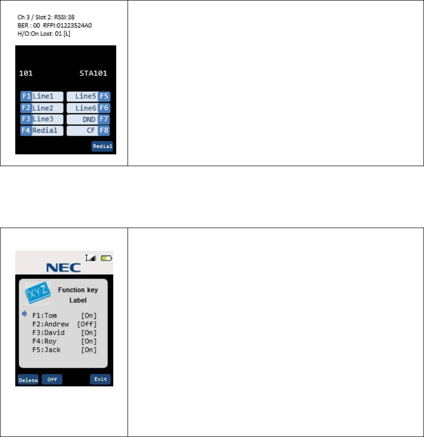
3.16.23 Administrator Setting (Site Survey:Sync Display mode)
Step 1 To Start Sync Display mode, press Sync key..
Sync Display mode is activated Sync information display in
each state.
Sync display includes following contents.
Ch: Current channel number.
Slot: Current Slot number.
RSSI: Current RSSI value.
BER: Bit Error Rate
RFPI: Base RF ID
H/O: Hand Over Enable/Disable
Lost: Lost counter
[L ]: status (Locked , Unlock)
3.16.24 Function Key Label
Step 1 Press the menu/mute key in standby mode. Then the LCD shows menu list mode.
Step 2 Select “Key Label” and press select key.
Pointer is pointed to the F1(fixed).
There are 8 function key labels setting available.
In this screen, following keys are available.
up/down key:
Pointer moves
select key:
Enter Label name edit screen.
Delete key:
Delete Label name.
On/Off key:
Toggle switch of Function Key Enable/Disable.
55
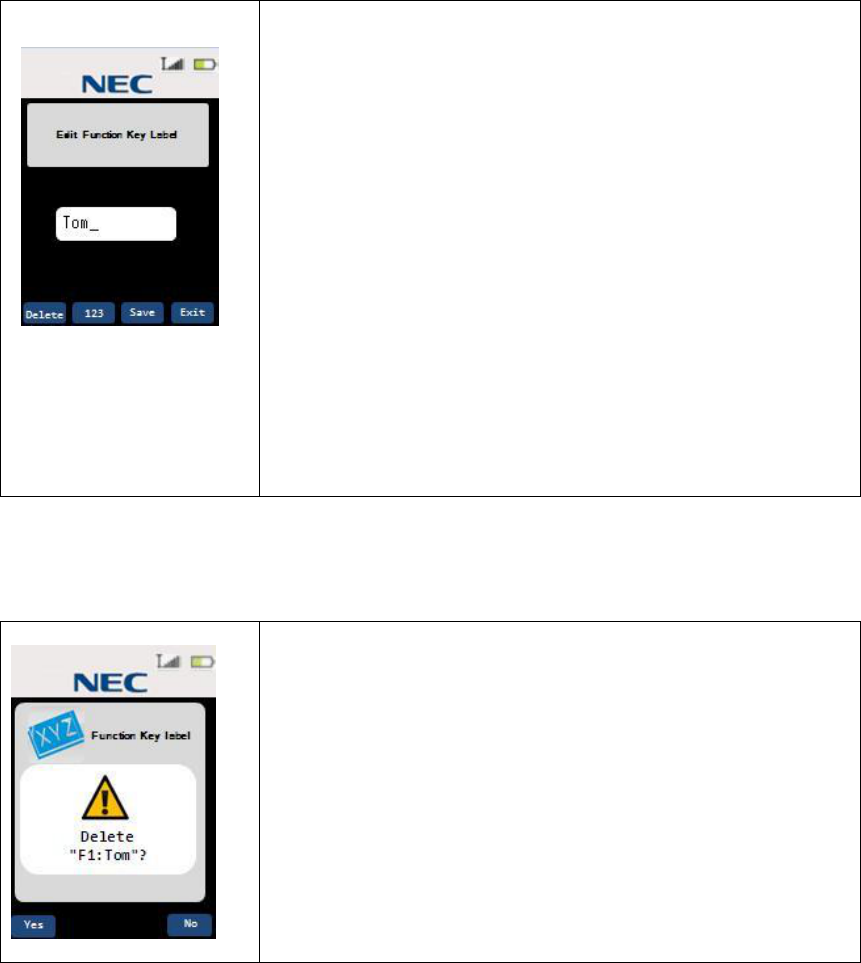
3.16.25 Function Key Label(Name Edit)
Step 1 Press the select key in Function Key Label list screen. Then the LCD shows Name
Edit screen.
In this screen, following keys are available.
Maximum 8 characters can be stored in each label.
123/abc key(toggle)
“123” : To numeric input
“abc” : To alphabetical input
Delete Key
Delete character of cursor position
Save Key
Store new function key label
[Alphabetical input]
Dial Keys (Refer in Edit Contact list name)
Right/Left Key(alphabetical Input only)
Cursor moves
3.16.26 Function Key Label(Delete Label)
Step 1 Press the Delete key in Function Key Label list screen. Then the LCD shows
confirmation screen.
In this screen, following keys are available.
Yes key:
Delete Function key label
No key:
Return to previous screen.
56
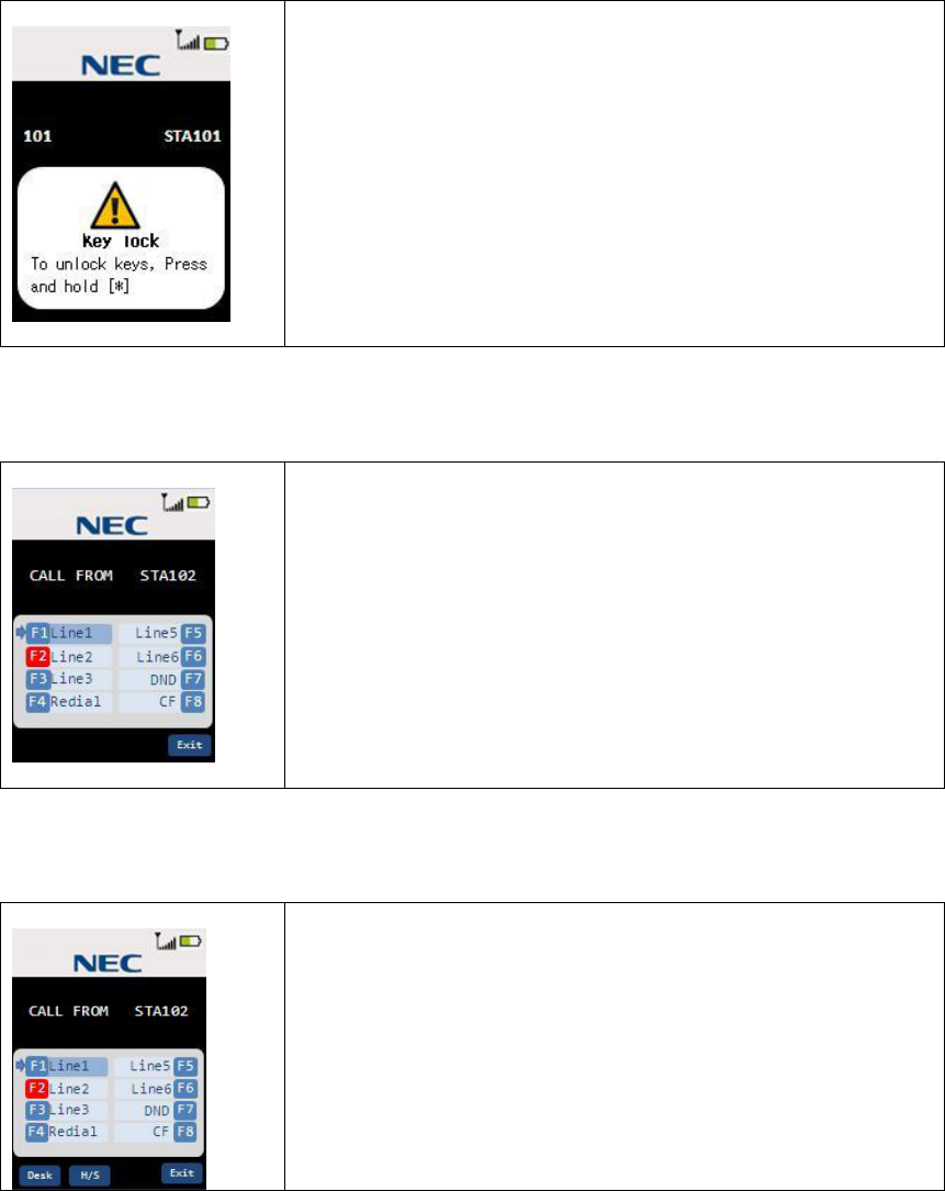
3.17 Key Lock
In standby state, If Key lock function is enabled, 15 seconds elapsed from last key operation,
Key lock is activated.
If Key is pressed while activating key lock, following screen appears.
In this screen, following keys are available.
* key(Press and hold 2 seconds):
Key is unlocked for a while.
1. If receive incoming call, Key lock function is disabled while
incoming calling.
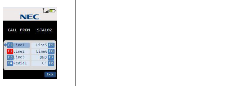
3.18 Virtual Function Key
In standby or Incoming call,Talk, Enter Virtual Function key mode by pressing the select key.
In this screen, following keys are available.
up/down/Right/Left key:
Select Function key
select key / talk key / speaker key:
Send Function key code to the base station.
And, Exit from Virtual function key mode.
3.19 Base Key Option (Option)
If Base key option is On, In Virtual Function key screen,
following keys are available.
Desk key: Same as base left key
H/S key: Same as base right key
Other keys:Same as Virtual Function key mode
57
3.20 Speed Dial Settings (Option)
If Speed Dial setting option is On, In Virtual Function key
screen, following keys are available.
Dial1-0 key: Dialing from Contact list if it registered.
Dial 1:Contact List 01
Dial 2:Contact List 02
:
Dial 0:Contact List 10
Other keys:Same as Virtual Function key mode
58
4. Appendix
4.1 Data Table
4.1.1 Factory Setting
ITEM HANDSET BASE STATION
Security Code N/A 1234
Redial None N/A
One Touch Dial Number None N/A
Ringer Tone Tone A N/A
Ringer Volume High N/A
Ringer Mute Off N/A
Ear Speaker Volume 4 N/A
Hands Free Volume 4 N/A
Headset Volume 4 N/A
Brightness
MAX
N/A
Power Save
ON
N/A
Contact List
None
N/A
Function Key Label None (ON) N/A
Language English N/A
Key Tone ON N/A
Vibrate ON N/A
Audio Equalizer Normal N/A
Menu Timeout 30seconds N/A
Key Lock OFF N/A
Out Of Range Alert ON N/A
Redial Option Enable N/A
Speed Dial Option Disable N/A
Base Key Option Disable N/A
Word Wrapping 24×2line (48digits) N/A
Handset Expandability
Disable
N/A
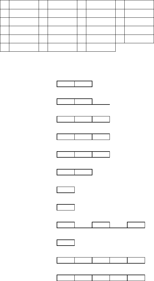
4.1.2 Timings
ITEM VALUE UNIT
Handset Key detect (Chattering processing) Time 30 msec
Handset Charge detect (Chattering processing) Time 500 msec
Handset Low battery (Chattering processing) Time 10 sec
Handset Headset detect Cycle 500 msec
Handset LCD refresh Cycle 1 sec
Base Key detect(Chattering processing) Time 30 msec
Base DTMF dial output time 100 (*1) msec
*1:There is no continuous DTMF signaling.

Important Safety Instructions
When using your telephone equipment, basic
safety precautions should always be followed to
reduce the risk of fire, electric shock and injury
to persons, including the following:
This unit is NOT waterproof. DO NOT expose
it to rain or moisture.
Do not use this product near water, for example,
near a bath tub, wash bowl, kitchen sink or
laundry tub, in a wet basement or near a
swimming pool.
Avoid using a telephone (other than a cordless
type) during an electrical storm. There may be a
remote risk of electric shock from lightning.
Do not use the telephone to report a gas leak in
the vicinity of the leak.
Use only the power cord and batteries indicated
in the manual. Do not dispose of batteries in a
fire. They may explode. Check with local codes
for possible special disposal instructions.
Do not place the handset in any charging cradle
without the battery installed and the battery
cover securely in place.
SAVE THESE INSTRUCTIONS!
CAUTION! Risk of explosion if battery is
replaced by an incorrect type! Dispose of
used batteries according to the
instructions. Do not open or mutilate the
battery. Disconnect the battery before
shipping this product.
Rechargeable Battery Warning
If your equipment contains a rechargeable
Nickel-Metal-Hydride (Ni-MH) battery:
Nickel is a chemical known to the state of
California to cause cancer.
Do not short-circuit the battery.
The batteries in this equipment may explode if
disposed of in a fire.
Do not charge the batteries in any charger other
than the one specified in the owner's manual.
Using another charger may damage the
battery or cause it to explode.
As part of our commitment to protecting our
environment and conserving natural resources,
Uniden voluntarily participates in an RBRC®
industry program to collect and recycle used Ni-
MH batteries within the United States. Please
call 1-800-8-BATTERY for
information on Ni-MH battery
recycling in your area.
(RBRC® is a registered
trademark of the
Rechargeable Battery
Recycling Corporation.)
Rechargeable batteries must be recycled
or disposed of properly.
COMPLIANCE INFORMATION
FCC Part 15 Information
This device complies with part 15 of the FCC
rules. Operation is subject to the following two
conditions: (1) This device may not cause
harmful interference, and (2) This device must
accept any interference received, including
interference that may cause undesired operation.
Privacy of communications may not be ensured
when using this phone.
FCC PART 15.105(b): Note: This equipment
has been tested and found to comply with the
limits for a Class B digital device, pursuant to
part 15 of the FCC Rules. These limits are
designed to provide reasonable protection
against harmful interference in a residential
installation. This equipment generates, uses and
can radiate radio frequency energy and, if not
installed and used in accordance with the
instructions, may cause harmful interference to
radio communications. However, there is no
guarantee that interference will not occur in a
particular installation. If this equipment does
cause harmful interference to radio or television
reception, which can be determined by turning
the equipment off and on, the user is
encouraged to try to correct the interference by
one or more of the following measures:
Reorient or relocate the receiving antenna.
Increase the separation between the equipment
and receiver.
Connect the equipment into an outlet on a circuit
different from that to which the receiver is
connected.
Consult the dealer or an experienced radio/TV
technician for help.
FCC RF Exposure Information
This product complies with FCC radiation
exposure limits under the following conditions:
The base must be placed to allow a minimum of
20 cm (8 inches) between the antenna and all
persons during normal operation.
The base must not be collocated or operated in
conjunction with any other antenna or
transmitter.
The handset is designed for body-worn
operation and meets FCC RF exposure
guidelines when used with any belt clip, carrying
case, or other accessory supplied with this
product. (All necessary accessories are included
in the package; any additional or optional
accessories are not required for compliance with
the guidelines.) Third party accessories (unless
approved by the manufacturer) should be
avoided as these might not comply with FCC RF
exposure guidelines.
Industry Canada (I.C.) Notice
Terminal equipment
NOTICE: This equipment meets the applicable
Industry Canada Terminal Equipment Technical
Specifications. This is confirmed by the
registration number. The abbreviation IC before
the registration number signifies that registration
was performed based on a Declaration of
Conformity indicating that Industry Canada
technical specifications were met. It does not
imply that Industry Canada approved the
equipment.
Radio equipment
The term IC before the radio certification
number only signifies that Industry Canada
technical specifications were met. Operation is
subject to the following two conditions: (1) this
device may not cause interference, and (2) this
device must accept any interference, including
interference that may cause undesired operation
of the device. "Privacy of communications may
not be ensured when using this telephone".
Environmental Requirements
Only use the cordless telephone in
temperatures between -10 ºC to +50 ºC
(+14 ºF to +122 ºF).
Avoid exposing the cordless telephone to
direct sunlight or close to other heat
sources.
Do not expose the cordless telephone to
open flame.
Keep the cordless telephone away from
excessive heat and moisture.
Avoid sudden temperature changes to
prevent condensation in the cordless
telephone. It is recommended to put the
cordless telephone into an air tight plastic
bag until the temperature is adjusted, for
example, when entering or leaving a
cold/heated building on a warm/cold day.
Protect your cordless telephone from
aggressive liquids and vapors.
If the cordless telephone has been
exposed to water or condensation, remove
the battery immediately and let it dry
completely before re-inserting the battery.
Keep the cordless telephone away from
strong electromagnetic fields.
Do not place a cold cordless telephone in
a charger.