Uniden America UP689R 1.9 GHz UPCS Cordless Telephone - Handset User Manual
Uniden America Corporation 1.9 GHz UPCS Cordless Telephone - Handset Users Manual
UserManual.wiki
>
Uniden America
>
UP689R User Manual
Users Manual
Navigation menu
Upload a User Manual
Namespaces
Wiki Guide
HTML
PDF
Info
Views
User Manual
Discussion / Help
Navigation
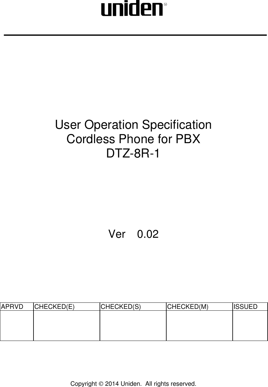
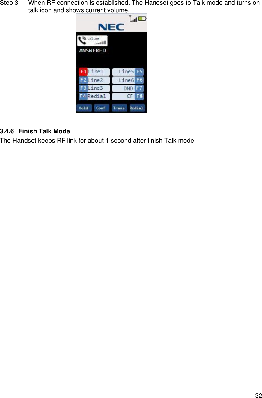
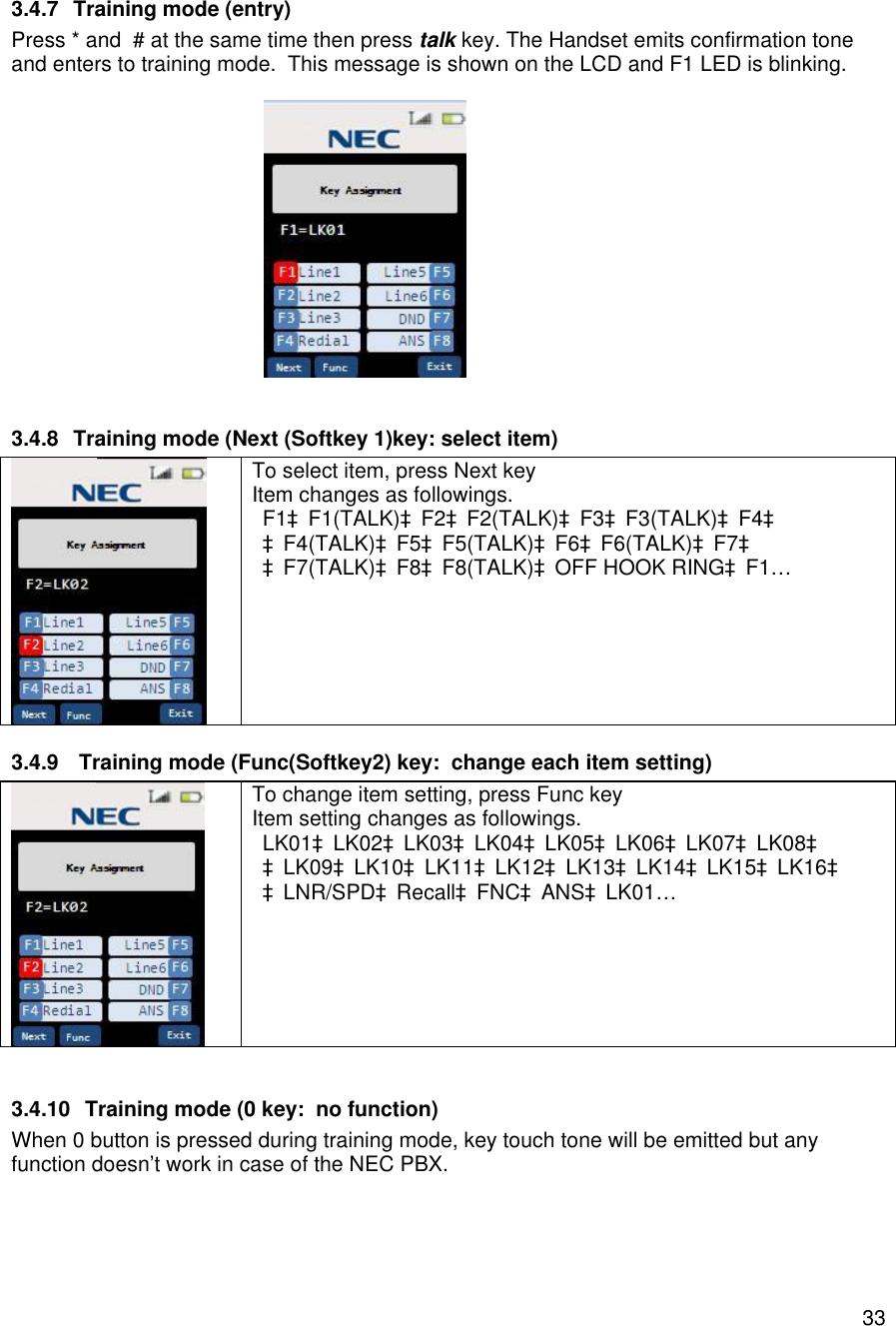
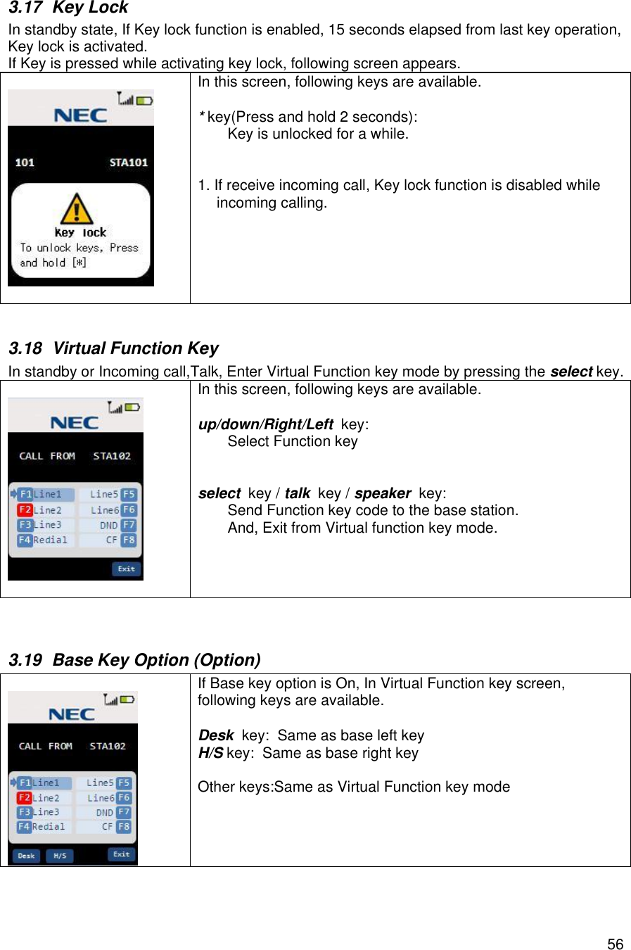
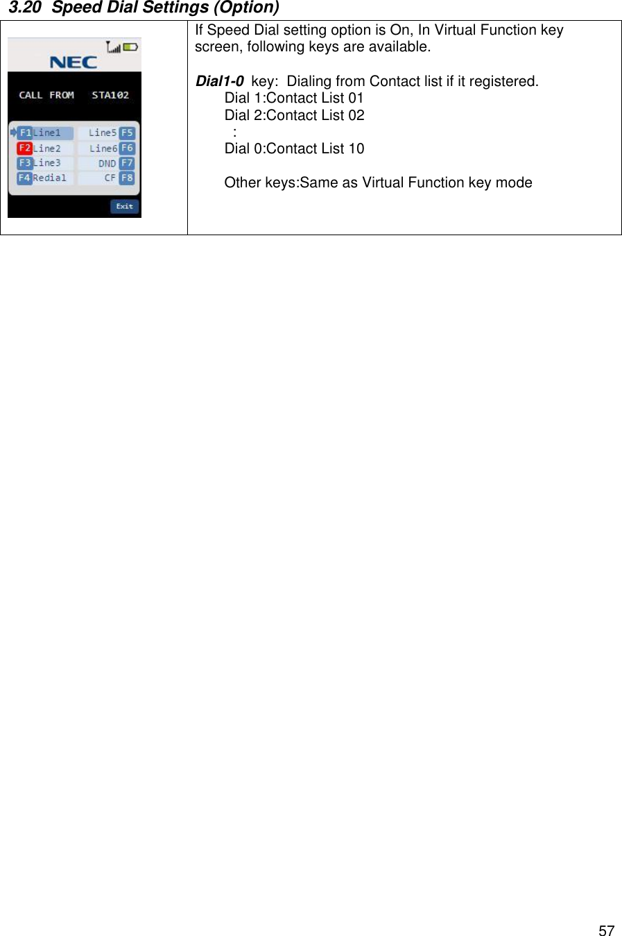
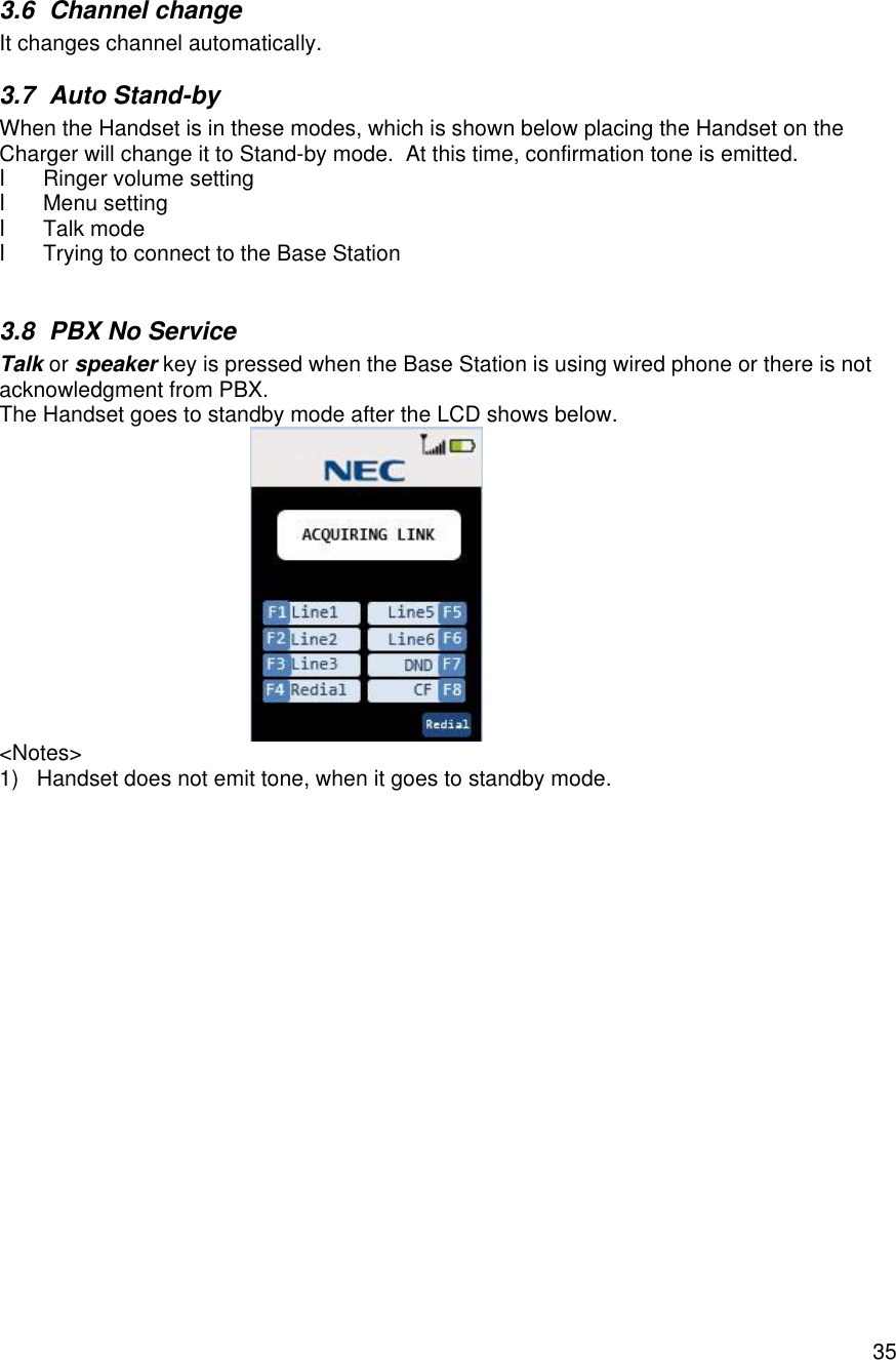
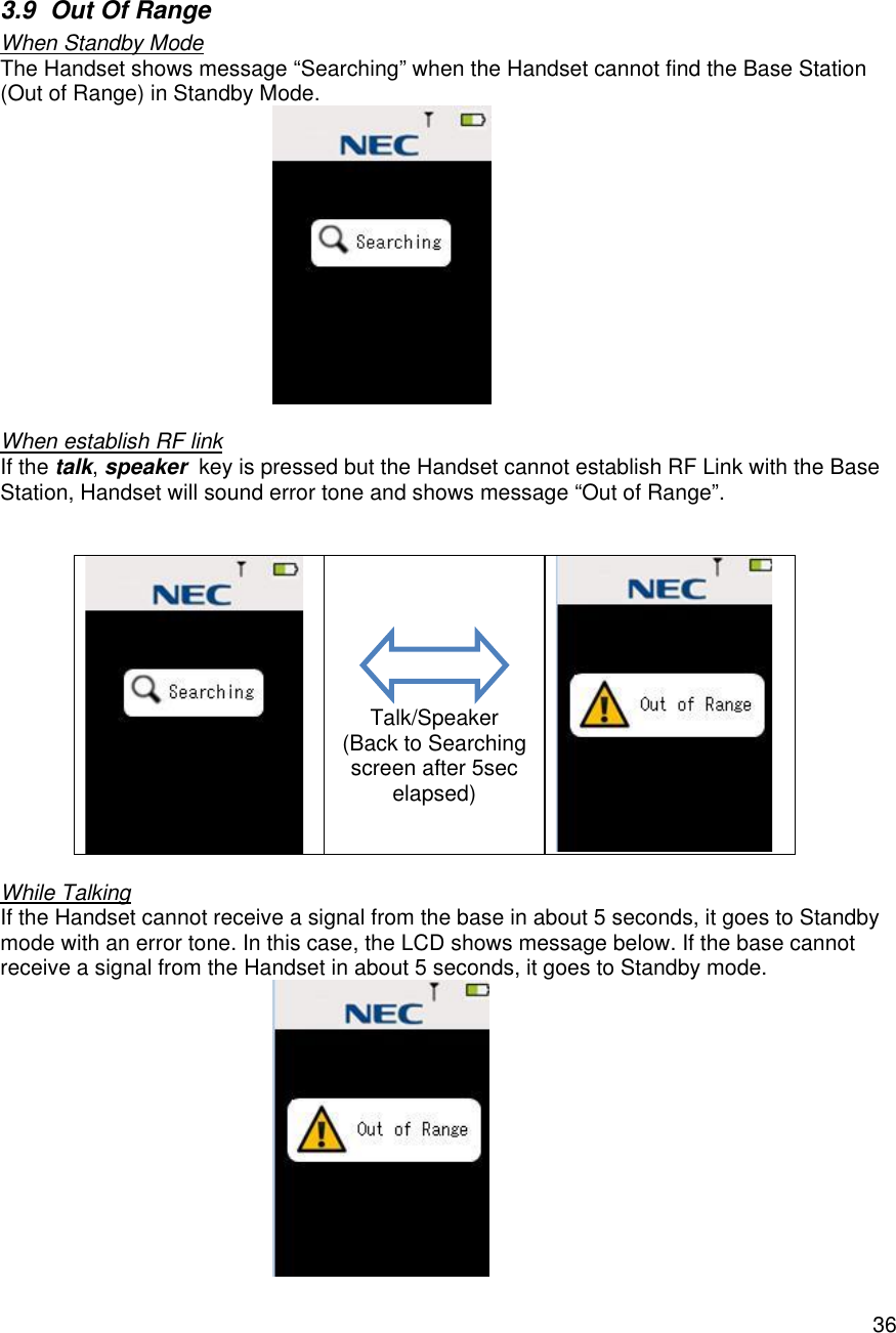
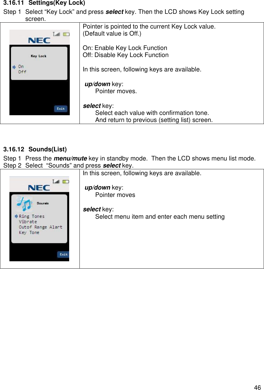
![343.4.11 Training mode (Exit(softkey 4) key: exit from the Training mode) When Exit key is pressed anytime during training mode, key touch-tone will be emitted and “Training off” command is sent to the PBX Expansion board. The Handset will exit from the Training mode. 3.5 REDIAL (Option) When the RF link is established between the Handset and the Base Station and no dial key operation is performed. If the user presses redial key, the last number dialed will be shown and these dials will be sent to the Base Station. <Notes> 1) Error tone will be emitted when redial is empty. 2) Dial limit is 32 digits, so redial will store up to 32 digits in memory. 3) Redial data is stored in Handset memory (EEPROM). 4) If F1-F12 key is pressed the number dialed before Function key is pressed will be stored in redial memory. 5) redial key is invalid when the Handset outputted dial. This means redial key is valid as 1st dial. <Example> (1) [talk][1][2][3][talk] redial: 123 (2) [talk][1][2][3]……….[1][2][talk] (over 32digits) redial: 123……12 (up to 32digits) (3) [talk][1][2][3][F1][4][5][6][talk] redial: 123](https://usermanual.wiki/Uniden-America/UP689R/User-Guide-2355625-Page-35.png)
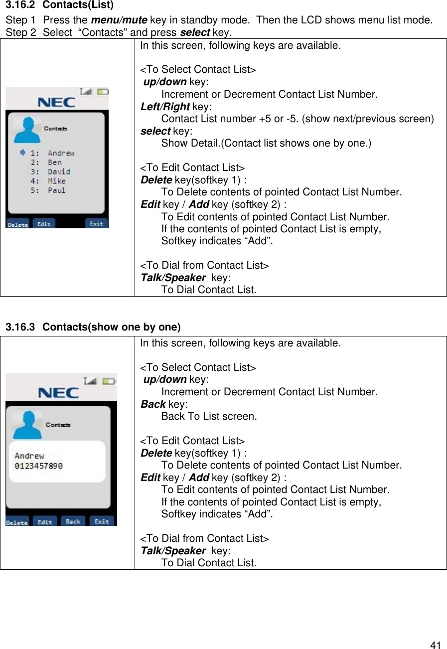
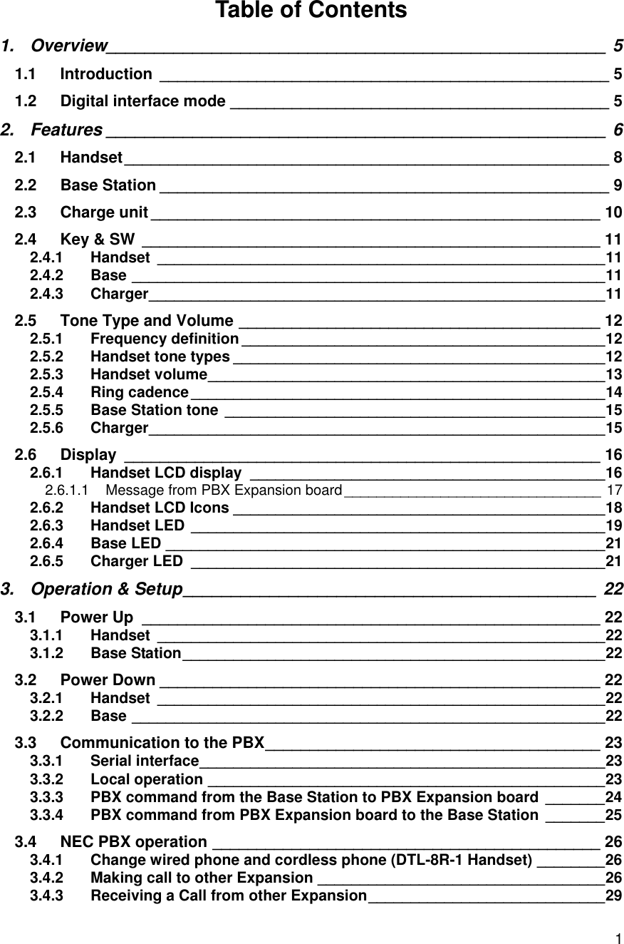
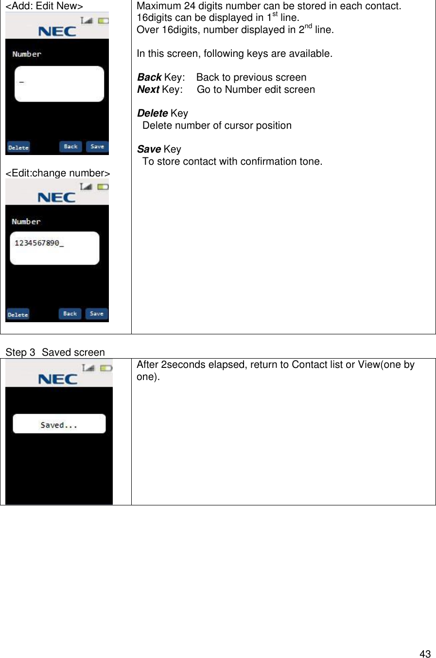
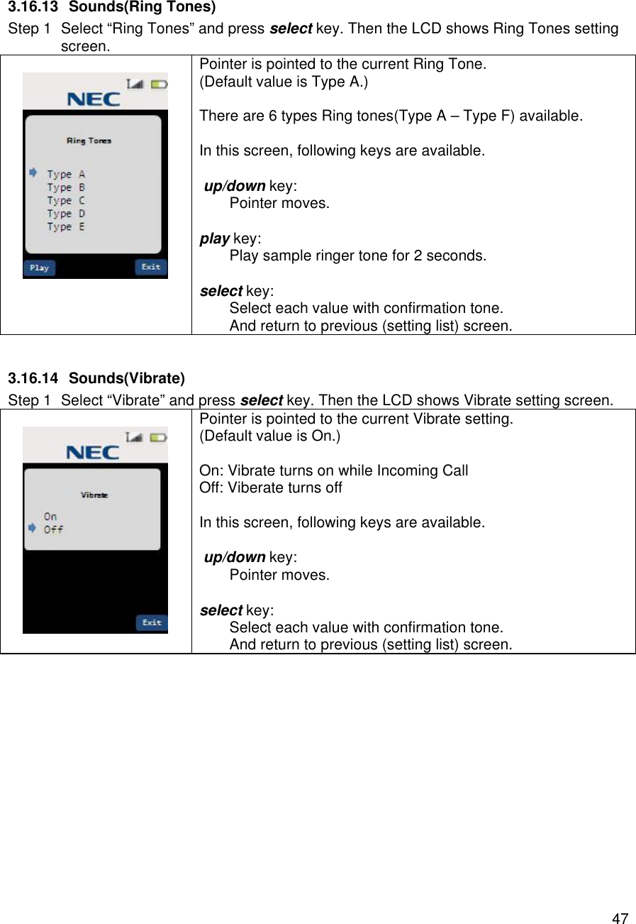
![423.16.4 Contacts(Delete Contact) In this screen, following keys are available. Yes key: Delete Contact with confirmation tone. After Delete contents, Back to Previous screen. No key: Back To previous screen. 3.16.5 Contacts(Edit/Add) Step 1 Enter Name for contact. <Add: Edit New> <Edit:Rename> Maximum 8 characters can be stored in each contact. In this screen, following keys are available. Back Key: Back to previous screen Next Key: Go to Number edit screen 123/abc key(toggle) “123” : To numeric input “abc” : To alphabetical input Delete Key Delete character of cursor position [Alphabetical input] Dial Keys Dial 1 : @.-_&'^?!(),\\/:;~=+1 Dial 2 : abcABC2 Dial 3 : defDEF3 Dial 4 : ghiGHI4 Dial 5 : jklJKL5 Dial 6 : mnoMNO6 Dial 7 : pqrsPQRS7 Dial 8 : tuvTUV8 Dial 9 : wxyzWXYZ9 Dial 0 : 0 Dial * : * Dial # : # Right/Left Key(alphabetical Input only) Cursor moves Step 2 Enter Number for contact.](https://usermanual.wiki/Uniden-America/UP689R/User-Guide-2355625-Page-43.png)
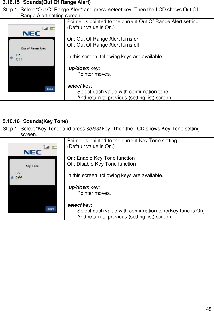

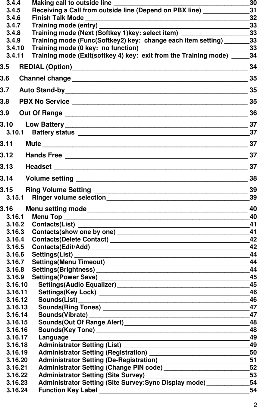
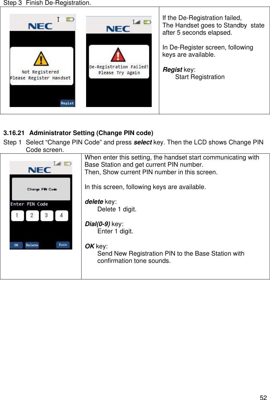
![513.16.20 Administrator Setting (De-Registration) Step 1 Select “De-Registration” and press select key. Then the LCD shows De-Registration screen. Display Available Handset number(Handset #1 only) As for Operating Handset, display ”[Using]” next of Handset #. In this screen, following keys are available. up/down key: Pointer moves (If the other handset registered) select key: Select pointed handset and goes to confirmation display. Step 2 To start De-Registration, press Yes Key. In this screen, following keys are available. Yes key: Start De-Registration No key: Return to Standby state.](https://usermanual.wiki/Uniden-America/UP689R/User-Guide-2355625-Page-52.png)
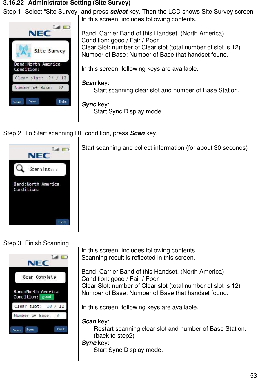
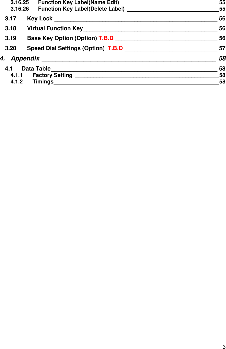
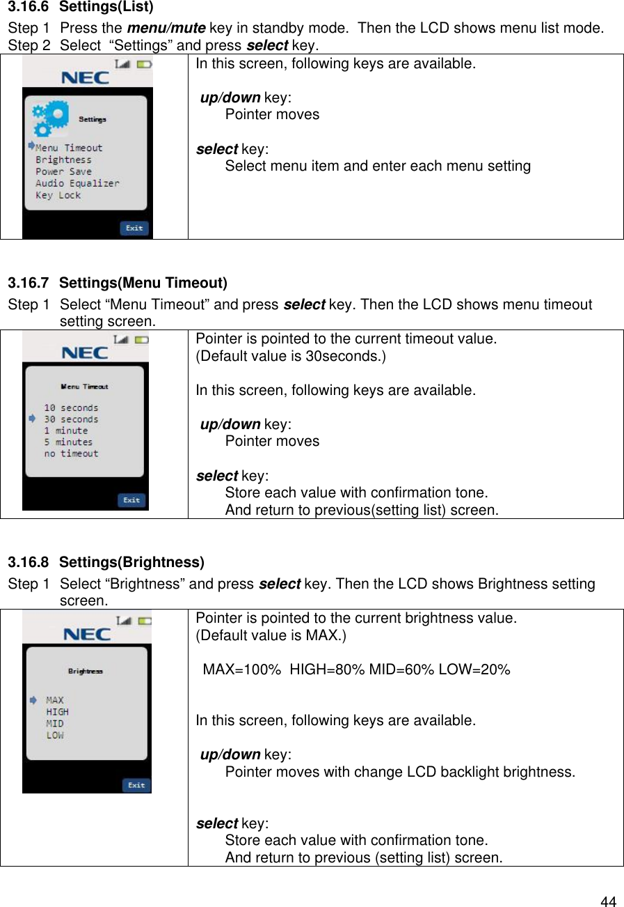
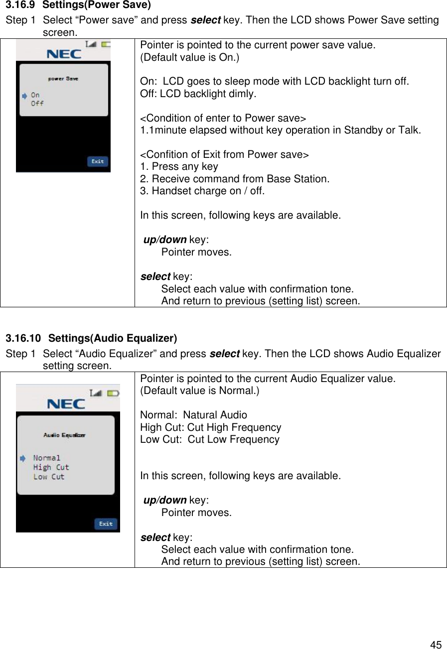
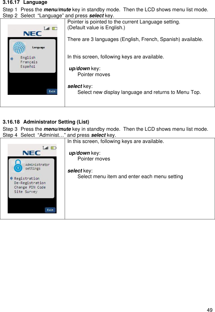
![54 3.16.23 Administrator Setting (Site Survey:Sync Display mode) Step 1 To Start Sync Display mode, press Sync key.. Sync Display mode is activated Sync information display in each state. Sync display includes following contents. Ch: Current channel number. Slot: Current Slot number. RSSI: Current RSSI value. BER: Bit Error Rate RFPI: Base RF ID H/O: Hand Over Enable/Disable Lost: Lost counter [L ]: status (Locked , Unlock) 3.16.24 Function Key Label Step 1 Press the menu/mute key in standby mode. Then the LCD shows menu list mode. Step 2 Select “Key Label” and press select key. Pointer is pointed to the F1(fixed). There are 8 function key labels setting available. In this screen, following keys are available. up/down key: Pointer moves select key: Enter Label name edit screen. Delete key: Delete Label name. On/Off key: Toggle switch of Function Key Enable/Disable.](https://usermanual.wiki/Uniden-America/UP689R/User-Guide-2355625-Page-55.png)
![55 3.16.25 Function Key Label(Name Edit) Step 1 Press the select key in Function Key Label list screen. Then the LCD shows Name Edit screen. In this screen, following keys are available. Maximum 8 characters can be stored in each label. 123/abc key(toggle) “123” : To numeric input “abc” : To alphabetical input Delete Key Delete character of cursor position Save Key Store new function key label [Alphabetical input] Dial Keys (Refer in Edit Contact list name) Right/Left Key(alphabetical Input only) Cursor moves 3.16.26 Function Key Label(Delete Label) Step 1 Press the Delete key in Function Key Label list screen. Then the LCD shows confirmation screen. In this screen, following keys are available. Yes key: Delete Function key label No key: Return to previous screen.](https://usermanual.wiki/Uniden-America/UP689R/User-Guide-2355625-Page-56.png)