Uniden America UT390 AM MOBILE CB TRANSCEIVER WITH WEATHER ALERT User Manual
Uniden America Corporation AM MOBILE CB TRANSCEIVER WITH WEATHER ALERT Users Manual
UserManual.wiki
>
Uniden America
>
UT390 User Manual
>
Users Manual
Contents
1.
FCC Rules
2.
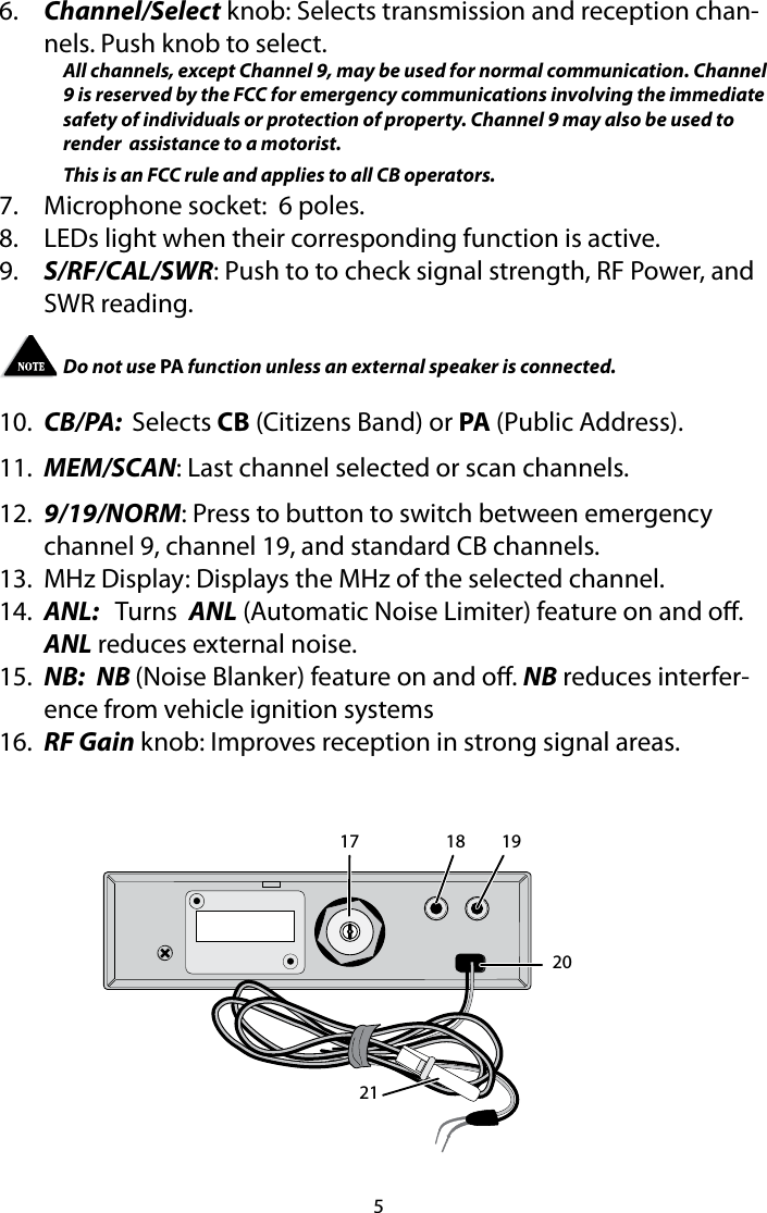
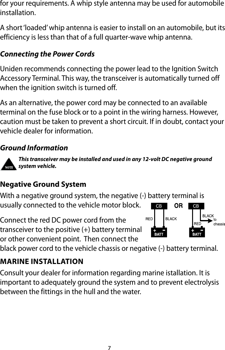
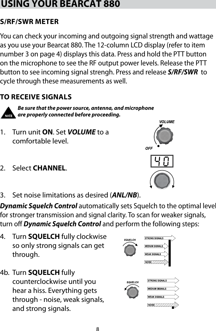
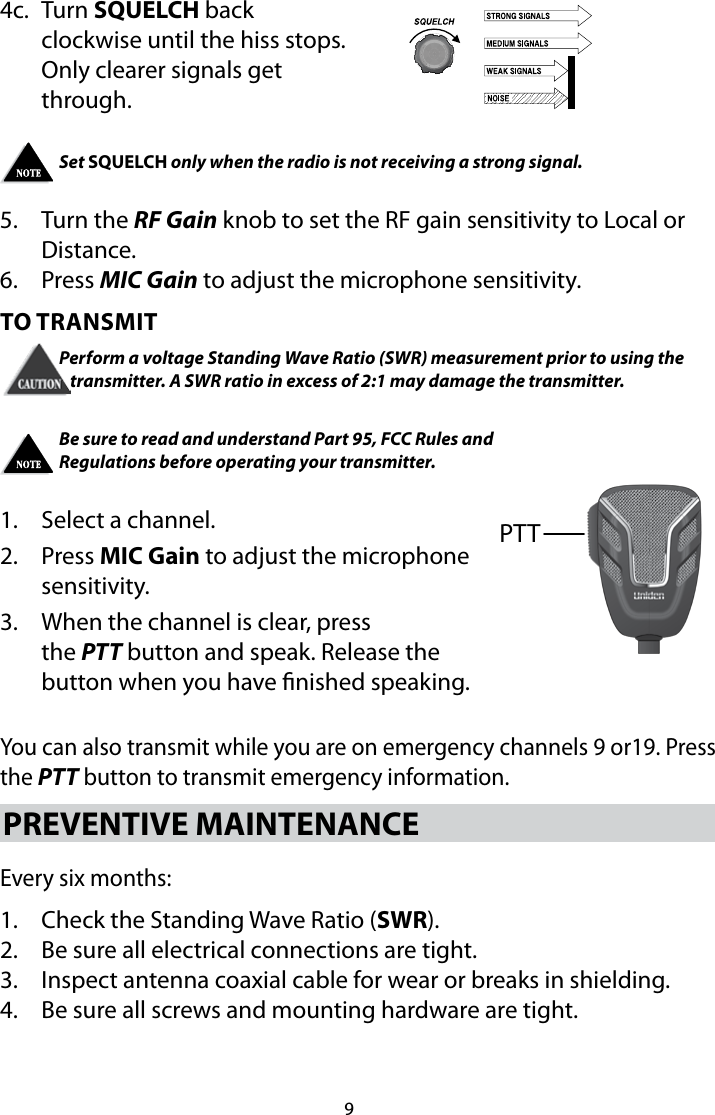
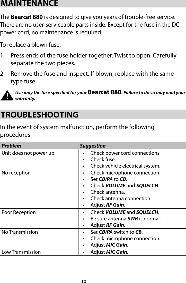
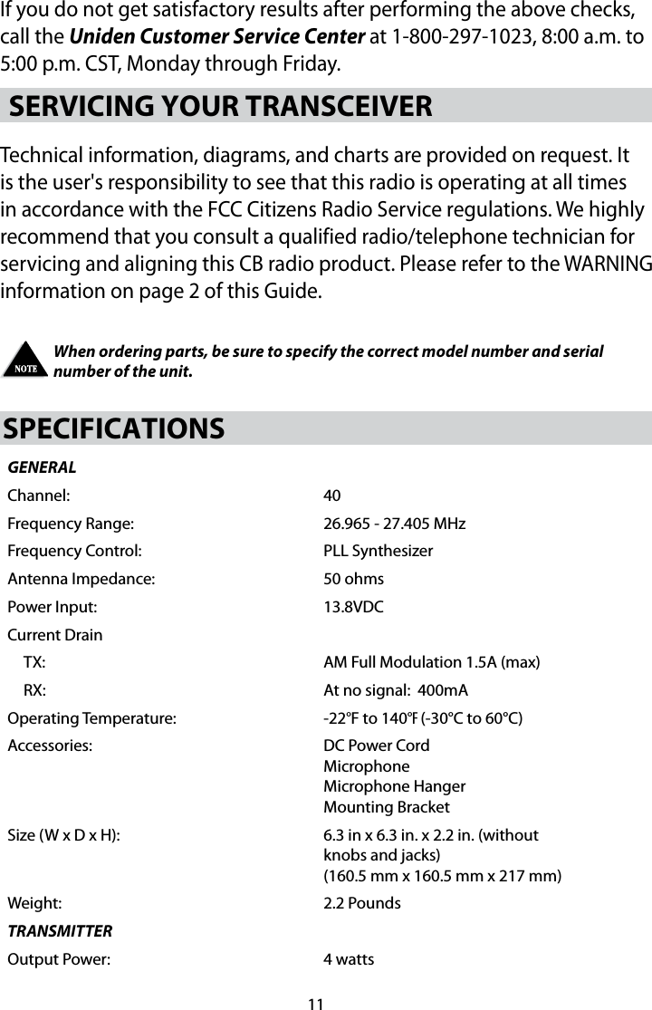
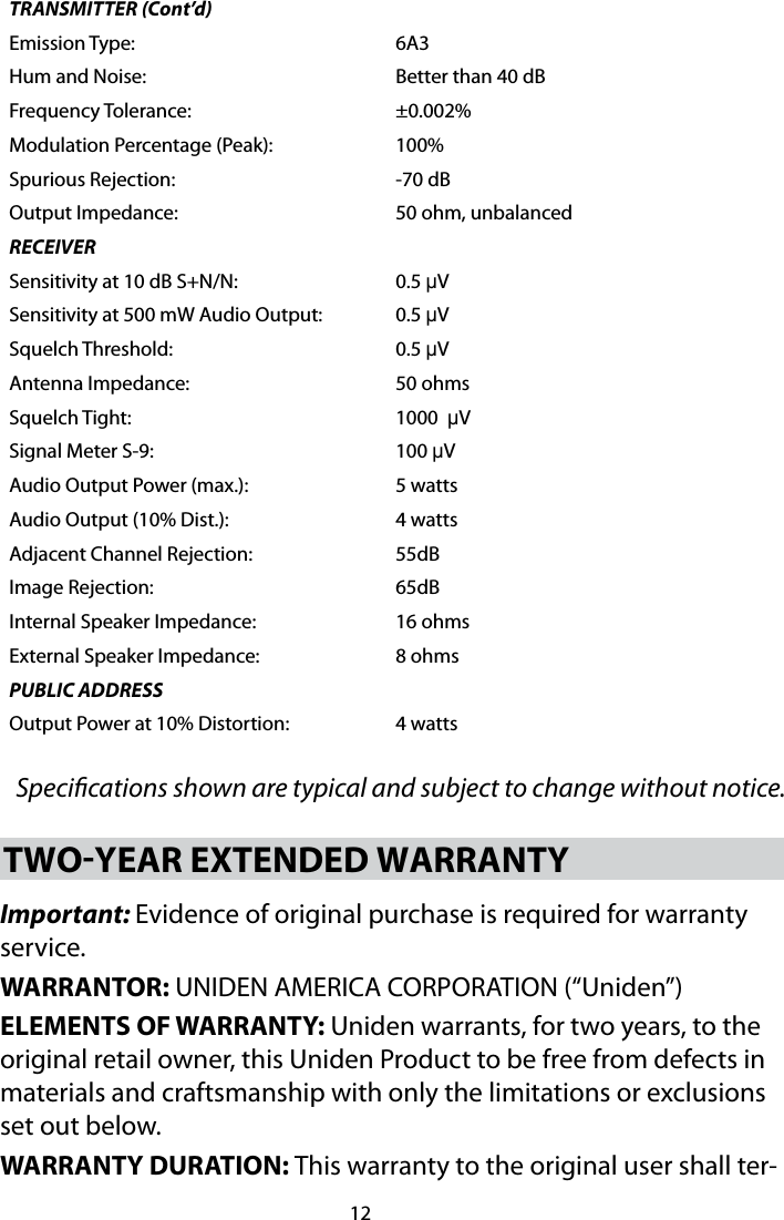
Users Manual
Users Manual
Navigation menu
Upload a User Manual
Namespaces
Wiki Guide
HTML
PDF
Info
Views
User Manual
Discussion / Help
Navigation