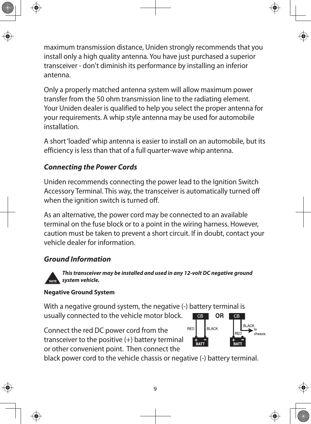
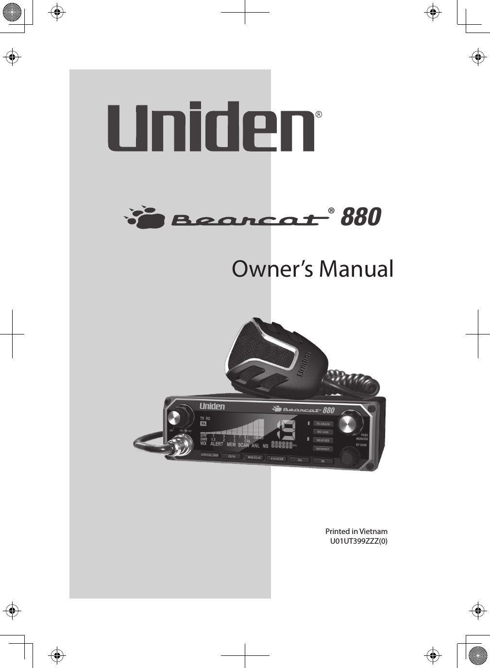
Uniden America UT399 CB Transceiver with Weather Alert User Manual USERS MANUAL EN
Uniden America Corporation CB Transceiver with Weather Alert USERS MANUAL EN
UserManual.wiki
>
Uniden America
>
UT399 User Manual
>
USERS MANUAL EN
Contents
1.
CB RADION RULES MANUAL
2.
USERS MANUAL EN
3.
USERS MANUAL SP
USERS MANUAL EN
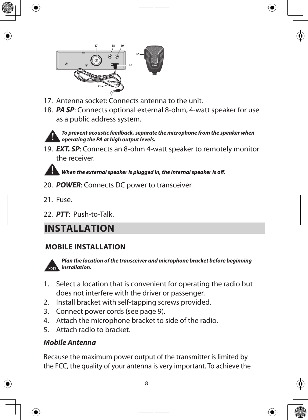
Navigation menu
Upload a User Manual
Namespaces
Wiki Guide
HTML
PDF
Info
Views
User Manual
Discussion / Help
Navigation
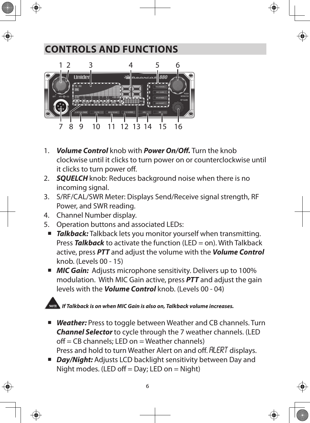
![76. Channel Selector/MENU/OK. Press the inner MENU/OK button to select a menu option or other selection. Turn the outer Channel Selector knob to: Select channels Select menu modes Change scan resume direction (up or down) Control Talkback volume Control Mic gain level Control Calibration volumeAll channels except Channel 9 may be used for normal communication. The FCC reserves Channel 9 for emergencies involving the immediate safety of individuals or protection of property. Use Channel 9 to render assistance to a motorist.This is an FCC rule and applies to all CB operators.7. Microphone socket.8. Indicators turn on when the function is turned on.9. S/RF/CAL/SWR: Push to to check RF signal strength, calibration, and SWR reading.10. CB/PA: Selects CB (Citizens Band) or PA (Public Address). Do not use the PA function unless an external speaker is connected. 11. MEM/SCAN: Press to start or stop scanning modes [All Channel Scan (see page 11) and Memory Scan (see page 12)]. Press and hold to set or clear channel memory while in Memory mode.12. 9/19/NORM: Press to switch between emergency channel 9, channel 19, and standard CB channels. 13. Frequency Display: Displays the MHz of the selected channel. Also displays menu options. 14. ANL: Turns ANL (Automatic Noise Limiter) feature on and o. ANL reduces external noise.15. NB: Turns NB (Noise Blanker) feature on and o. NB reduces interference from vehicle ignition systems.16. RF Gain knob: Improves reception in strong signal areas.](https://usermanual.wiki/Uniden-America/UT399.USERS-MANUAL-EN/User-Guide-2179673-Page-7.png)