Uniden America UT416 CB RADIO WITH SCANNING RECEIVER User Manual BC885
Uniden America Corporation CB RADIO WITH SCANNING RECEIVER BC885
Contents
- 1. BC885 User Manual
- 2. FCC Part 95 User Manual
- 3. User Manual
BC885 User Manual
Owner’s Manual
Printed in Vietnam
U01UT416ZZZ(0)
BearTracker 885
©2017 Uniden America Corporation
Uniden is a registered trademark of Uniden America Corporation.
Features, specications, and availability of optional
accessories are all subject to change without notice.

CONTENTS
OVERVIEW .................................................................................. 7
IT’S A SCANNER - ...................................................................................... 7
AND A CB RADIO - ..................................................................................... 7
AND AN EARLY-WARNING SYSTEM ......................................................... 8
FEATURES ................................................................................................... 8
WHAT’S IN THE BOX .................................................................................. 9
CONTROLS AND FUNCTIONS ................................................................... 9
INSTALLATION .......................................................................... 12
MOBILE INSTALLATION ......................................................................... 12
Safety Notice ......................................................................................... 12
Antennas ............................................................................................... 13
GPS Receiver ......................................................................................... 13
Connecting the Power Cords ............................................................... 14
Ground Information ............................................................................. 14
MARINE INSTALLATION ......................................................................... 14
SET UP BEARTRACKER 885 ...................................................... 14
BEARTRACKER 885 INITIAL SETUP ........................................................ 14
BASIC OPERATIONS ................................................................. 15
EMERGENCY OPERATION ...................................................................... 15
BASIC OPERATIONS................................................................................. 16
USING THE KEYS ...................................................................................... 17
SRF/CAL/SWR Key ................................................................................. 17
CB/PA/WX|WX ALT Key .......................................................................... 17
ANL/NB|TALKBACK Key ....................................................................... 18
9/19|DAY/NIGHT Key ........................................................................... 18
FUNC|MIC GAIN Key ............................................................................. 18
S. MUTE | AVOID Key ............................................................................. 19
Public Safety Keys ................................................................................. 19
WEATHER MODE (WX MODE) ................................................................. 19
SCANNER FEATURE ................................................................................ 20
FUNCTION KEY ........................................................................................ 21
Function + WX ALERT ............................................................................ 21
Function + Talkback ............................................................................. 21
Function + Day/Night ........................................................................... 22
Function + AVOID ................................................................................. 22
Function + ZIP ....................................................................................... 22
Function + S. SQL .................................................................................. 23
MENUS ...................................................................................................... 23
Select LCD Color ................................................................................... 23
Set LCD Contrast .................................................................................. 24
Set Brightness ....................................................................................... 24
LCD Color, Contrast, and Brightness Settings for Night LCD ............... 24
Set Weather Alert Scan ......................................................................... 24
Set BWS Alert ........................................................................................ 25
Set Audio Priority .................................................................................. 25
Set Tone ................................................................................................. 25
OTHER FEATURES .................................................................................... 26
SRF/CAL/SWR Meter ............................................................................. 26
Antenna System Check ......................................................................... 26
BEARTRACKER UPDATE MANAGER ....................................... 26
PREVENTIVE MAINTENANCE .................................................. 28
MAINTENANCE ......................................................................... 28
TROUBLESHOOTING ............................................................... 28
SERVICING YOUR TRANSCEIVER ........................................... 29
SPECIFICATIONS ....................................................................... 29
SCANNER .................................................................................................. 31
CTCSS FREQUENCIES .............................................................................. 32
DCS CODES .............................................................................................. 33
FCC PART 15/IC COMPLIANCE ................................................ 35
FCC COMPLIANCE .................................................................................... 35
IC COMPLIANCE ....................................................................................... 36
ONE-YEAR LIMITED WARRANTY ............................................ 37
RADIO CODE DEFINITIONS ..................................................... 39

E-7
UNIDEN CB + DIGITAL SCANNER
BearTracker 885
OVERVIEW
The BearTracker 885 combines Uniden’s top-rated Bearcat CB
communications technology and Uniden’s most popular scanners. Once
you know what public safety issues are ahead of you, you can talk to
others in that area for advice on avoiding traffic backup and other delays.
IT’S A SCANNER -
The BearTracker 885 includes a database of all known public safety
and DOT channels in the US and Canada. The included GPS allows the
scanner to select channels in your area, wherever you are. We update the
database weekly, so you can easily keep your BearTracker 885’s database
up-to-date using the BT885 Update Manager (see page 22). Listen to
these safety channels and always be aware of what’s ahead.
The BearTracker 885 cannot receive encrypted or some
proprietary types of digital systems
The scanner feature operates alongside the unit’s CB radio features. There
is no switching back and forth between modes; just press a button and
you’re listening to Police channels, Fire department channels, etc., while
standard CB channels are active.
AND A CB RADIO -
Like any CB radio, the BearTracker 885 opens communication between
you and other travelers. This full-featured CB radio provides 40 channels,
4-Watt RF power, a 7-color display, an SWR meter for precision antenna
tuning, RF Gain, Mic Gain, PA mode, Talkback, and NOAA weather
channels with an Alert function. An ergonomic, noise-cancelling
microphone enhances your transmissions, even in the noisy environment
of a tractor-trailer cab.
The Citizens Band Radio Service is under the jurisdiction
of the Federal Communications Commission (FCC). Any
E-8
adjustments or alterations which would alter the performance
of the transceiver’s original FCC type acceptance, or which
would change the frequency determining method, are strictly
prohibited.
Replacement or substitution of crystal, transistors, ICs,
regulator diodes, or any other part of a unique nature, with
parts other than those recommended by Uniden, may cause
violations of the technical regulations in Part 95 of the FCC
Rules or in violation of type acceptance requirements in Part 2
of the rules.
AND AN EARLY-WARNING SYSTEM
The BearTracker Warning System (BWS) alerts you whenever there is
nearby public safety radio traffic. The radio detects the public safety
vehicle’s radio’s low-power signals and alerts you if there are signals
up to about 3 to 5 miles from your location. If you are using this in a
commercial vehicle, it is NOT a radar detector but a completely legal
public safety service scanner.
Some states restrict the use of scanners in vehicles. Please
check your local state laws for any restrictions.
FEATURES
7-Color LCD Display
Day/Night LCD Settings
Weather Alert
Squelch Control
Weather Channel Scan
Emergency Channel 9
PA Function
Wireless Mic Compatible
Digital and Analog Police/Fire/Ambulance/DOT scanner
Scan system types include conventional analog and digital,
Motorola, LTR, EDACS, APCO P25 Phase I and Phase II
Includes VHF, UHF, 700/800 MHz
E-9
Quick avoid for unwanted channels
Individually select types of channels to receive
BearTracker Warning System
SWR Meter
CB/Scanner Audio Priority
Antenna System Check
Mic and RF Gain
Talkback
ANL/NB
WHAT’S IN THE BOX
Your BearTracker 885 contains the following:
BearTracker 885 CB 2-way mobile radio
Noise-Cancelling Microphone
Mounting Bracket Kit
DC Power Cord
Window-Mount Antenna
Micro-SD card and SD Card adapter (pre-installed)
GPS Receiver/RJ45 cable
Owner’s Manual
Part 95 Subpart D (FCC Rules)
If any items are missing or damaged, contact your place of purchase
immediately.
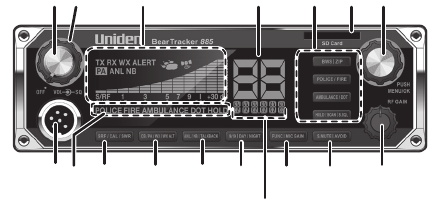
CONTROLS AND FUNCTIONS
1 42 5 7
8 1615
14
1211109 13
3
17
6
E-10
1. Volume Control knob with Power On/O. Turn the knob
clockwise until it clicks to turn power on. Continue turning the
knob clockwise to increase the volume. Turn the Volume Control
knob counterclockwise to decrease the volume or until it clicks to
turn power o.
2. SQUELCH knob: Reduces background noise when there is no
incoming signal (see page 15).
3. SRF/CAL/SWR Meter: Displays Receive signal strength, RF Power,
and SWR reading.
4. Channel Number display.
5. Public Safety Channels/Functions (see page 19)
• BWS|ZIP
• POLICE/FIRE
• AMBULANCE/DOT
• HOLD/SCAN|S.SQL
6. SD Card Slot
7. MENU/OK|Channel Selector. This knob accesses the menu
system and changes selections for the menus. It also changes
channels.
All channels except Channel 9 may be used for normal
communication. The FCC reserves Channel 9 for emergencies
involving the immediate safety of individuals or protection
of property. Use Channel 9 to render assistance to a motorist.
This is an FCC rule and applies to all CB operators.
8. Microphone socket.
9. Indicates which public safety channels are active.
10. SRF/CAL/SWR: Press to switch the display between Signal
Strength / RF Mode, Calibration Mode, and SWR Mode (see page
21).
11. CB/PA/WX|WX ALT: Selects CB (Citizens Band) PA (Public
Address), Weather, or Weather Alert.
Do not use the PA function unless an external speaker is
connected.
12. ANL/NB|TALKBACK: Controls ANL (Automatic Noise Limiter) and
E-11
NB (Noise Blanker) settings (on or o) Talkback lets you monitor
yourself when transmitting (see page 18).
13. 9/19|DAY/NIGHT: Press to switch between emergency channel 9,
channel 19, and standard CB channels.
14. Frequency Display: Displays the MHz of the selected channel. Also
displays menu options.
15. FUNC|MIC GAIN: Press once to access the second function of
other buttons (indicated after the vertical bar on the button).
Press twice to adjust Mic Gain (see page 18).
16. S.MUTE|AVOID: Scanner Mute mutes the voice from incoming
transmissions. AVOID lets you put channels on a temporary
avoid list so the scanner will skip them (see page 22).
17. RF Gain: Adjust Receive frequency (see page 13).
20
22 23
21
1918
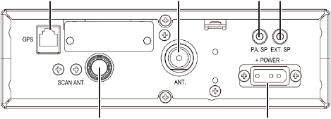
18. GPS Jack
19. CB Antenna socket: Connects antenna to the unit.
20. PA SP: Connects optional external 8-ohm, 4-watt speaker for use
as a public address system.
To prevent acoustic feedback, separate the microphone from
the speaker when operating the PA at high output levels.
21. EXT. SP: Connects 8-ohm 4-watt speaker to remotely monitor
receiver.
When an external speaker is plugged in, the internal speaker
is o.
22. Scanner Antenna Socket
23. POWER +12 VDC: Connects DC power to transceiver.

E-12
24. PTT: Push-to-Talk. Push microphone button.
24
INSTALLATION
MOBILE INSTALLATION
Safety Notice
The antenna used for this radio must be properly installed and
maintained. It must provide a separation distance of at least 23.8963
inches (61 cm) from all persons and must not be collocated or operated
in conjunction with any other antenna or transmitter. Never transmit if
any person is closer than the specified distance to the antenna.
Note that Uniden does not specify or supply any CB antenna with this
transceiver. While a 0 dBi gain antenna is normal for a typical installation,
the above limit applies to any antenna with up to 3 dBi gain.
Plan the location of the transceiver and microphone bracket
before beginning installation.
1. Select a location that is convenient for operating the radio but
does not interfere with the driver or passenger.
2. Install bracket with self-tapping screws provided.
3. Connect the power cords, antennas, and GPS module (included).
4. Attach the microphone bracket to side of the radio or car dash.
Hang the microphone in the bracket.
5. Insert radio into the bracket and secure it with the included
knobs.

E-13
Antennas
CB
Because the maximum power output of the transmitter is limited by
the FCC, the quality of your antenna is very important. To achieve the
maximum transmission distance, Uniden strongly recommends that you
install only a high quality antenna. You have just purchased a superior
transceiver; don't diminish its performance by installing an inferior
antenna.
Only a properly matched antenna system will allow maximum power
transfer from the 50-ohm transmission line to the radiating element.
Your Uniden dealer is qualified to help you select the proper antenna for
your requirements. A whip style antenna may be used for automobile
installation.
A short “loaded” whip antenna is easier to install on an automobile, but
its efficiency is less than that of a full quarter-wave whip antenna.
Scanner
Your radio kit includes a window-mount antenna. Follow the directions
included with the antenna for installation.
GPS Receiver
The GPS receiver provides location information so the radio can select
local public safety channels from the scanner database.
1. Connect the RJ45 cable to the GPS receiver and to the radio. The
GPS reciever automatically begins to acquire position information
from the satellite.
2. The GPS icon, , dispays in about 1 minute when the radio
receives GPS data. It remains on as long as GPS is connected and
receiving position information. The icon goes away if the GPS
disconnects and stops receiving position information.
E-14
Connecting the Power Cords
Uniden recommends connecting the power lead to the Ignition Switch
Accessory Terminal. This way, the transceiver is automatically turned off
when the ignition switch is turned off.
As an alternative, the power cord may be connected to an available
terminal on the fuse block or to a point in the wiring harness. However,
caution must be taken to prevent a short circuit. If in doubt, contact your
vehicle dealer for information.
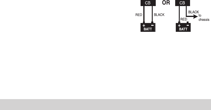
Ground Information
This transceiver may be installed and used in any 12-volt DC
negative ground system vehicle.
Negative Ground System
With a negative ground system, the negative (-) battery terminal is
usually connected to the vehicle motor block.
Connect the red DC power cord from the
transceiver to the positive (+) battery terminal
or other convenient point. Then connect the
black power cord to the vehicle chassis or negative (-) battery terminal.
MARINE INSTALLATION
Consult your dealer for information regarding marine installation. It
is important to adequately ground the system to prevent electrolysis
between the fittings in the hull and the water.
SET UP BEARTRACKER 885
BEARTRACKER 885 INITIAL SETUP
1. Remove SD card.
2. Install the GPS unit.
3. Insert the SD card into your computer (you may need an SD card
to USB adapter, not included). Update the database according to

E-15
procedures in the BearTracker Update Manager, page 26.
4. Remove the SD card from your computer and insert it back into
the SD card slot on your BearTracker 885.
5. Turn unit on. LOAD displays while the database on the SD card
downloads.
6. After the database completes downloading, NO POS displays
under the channel numbers. Wait for the unit to acquire GPS data.
If you are not using the GPS receiver, you must tell the unit
what local channels to use. Enter your zip code (USA) or the
rst 3 digits of your Canadian postal code. See page 22.
7. Set volume to a comfortable level (VOLUME knob).
8. Select channel (CHANNEL knob).
9. Turn noise limitations on or o as desired (ANL/NB|TALKBACK
key, see page 13).
10. Adjust CB Squelch (outer ring of VOL/SQ knob).
• Turn SQUELCH fully clockwise to receive strong signals.
• Turn SQUELCH fully counterclockwise until you hear a hiss. All
get through — noise, weak signals, and strong signals.
• Turn SQUELCH back clockwise until the hiss stops. Only
clearer signals get through.
Set SQUELCH only when the radio is not receiving a strong
signal.
11. Adjust Scanner Squelch (see page 23).
12. Turn RF Gain knob clockwise to adjust RF Gain upwards and
counter-clockwise to adjust RF Gain downwards. (CB mode only)
13. Adjust MIC Gain (see page 20).
14. Set LCD color (see page 23).
15. Set LCD contrast (see page 24).
16. Set LCD brightness (see page 24).
BASIC OPERATIONS
EMERGENCY OPERATION
1. Press 9/19|DAY/NIGHT or turn Channel Selector knob to Channel
9.

E-16
2. Press PTT on the microphone and speak clearly.
3. If there is no response, select an active channel and ask that party
to relay your emergency broadcast on Channel 9.
All channels except Channel 9 may be used for normal
communication. The FCC reserves Channel 9 for emergencies
involving the immediate safety of individuals or protection
of property. Use Channel 9 to render assistance to a motorist.
This is an FCC rule and applies to all CB radio operators.
HOW IT WORKS
The CB, scanner, and weather features work together without having to
change from one feature to another. For example, you can have CB active,
Police enabled, and Weather Alert activated. Weather alerts have priority
over CB and scanner operations, so if a weather alert is detected, a
special alert tone sounds when you are not transmitting. You can also set
whether CB or Scanner audio has priority through the menus (see page
23).
BASIC OPERATIONS
To Do This... Do this...
Update the scanner radio
channels to the latest version
See BearTracker Update Manager, page 26.
Set your location so that local
scanner channels are selected
• If you are using the GPS receiver
(included), be sure it is connected to the
radio. Wait for it to aquire GPS location
data.
• If you are not using the GPS receiver, enter
your location code (5-digit USA zip code
or rst 3-digits of your Canadian postal
code). The radio accesses local channels
from that area. See page 22.
GPS data overrides zip codes and postal codes.
Listen to weather channels Switch to Weather mode (see page 17) and
then turn on Scan (see page 19). The radio
will stop on a channel with a signal.

E-17
To Do This... Do this...
Listen to public safety channels Press a public safety key on the radio. (See item
#5 on page 9 and key descriptions on page
19.)
Decrease squelch so more CB
signals can get through
Adjust the squelch knob (see page 15).
Adjust scanner’s squelch level See page 23 for procedures.
Set which mode has priority for
voice signals
Set Audio Priority in Menus (see page 25).
Eliminate/reduce noise caused
by your vehicle’s electrical
system
Check Automatic Noise Limiter and Noise
Blanker levels (see page 18).
Change the LCD from day mode
to night mode
Make this change using the Function key and
9/19|Day/Night key (see page 22).
Check/calibrate the antenna See page 26 for procedures.
USING THE KEYS
SRF/CAL/SWR Key
This key checks incoming signal strength and received signal power or
allows you to tune your antenna for best performance. See page 26 for
operation details.
CB/PA/WX|WX ALT Key
This key lets you switch between CB, PA, and Weather modes. Enable/
disable the Weather Alert function using the Function key (see page
21).
1. Press the key once. CB is enabled. SCAN scrolls under the channel
number.
2. Press the key again. PA is enabled and PA displays on the LCD.
When you key the mic, PA replaces the channel number and
audio goes to the PA speaker only. As long as the radio is in PA
mode, any CB or scanner audio goes to the PA speaker.
3. Press the key a third time. Weather mode is enabled.
WX
displays on the LCD and the weather channel frequency number
displays under the channel number. You can hear local weather
E-18
information from the national weather service.
4. From Weather mode, press the key again. CB is active again.
ANL/NB|TALKBACK Key
Controls ANL (Automatic Noise Limiter) and NB (Noise Blanker) features
— ANL on, NB on, or both ANL and NB on or off. ANL reduces external
noise and NB reduces interference from vehicle ignition systems.
Talkback lets you monitor yourself when transmitting, and is accessed
with the Function key (see page 21).
1. Press
ANL/NB|TALKBACK. ANL displays (ANL function on).
2. Press the
key again. ANL goes off (ANL function off) and NB displays
(NB function on).
3. Press the
key again. Both ANL and NB display (ANL and NB functions
on).
4. Press the
key again. both ANL and NB go off (ANL and NB functions
off).
9/19|DAY/NIGHT Key
Press this key to switch to emergency service channels (9/19) and then
back to the starting channel. Switch between day and night LCD display
settings with the Function key (see page 22).
FUNC|MIC GAIN Key
If a key has the “
|
” symbol on it, the setting after that symbol cannot be
changed until Function is enabled. Press this key once to enable Function
operations. See page 21 for a description of this function and the
operations that are enabled with it.
The MIC Gain setting adjusts the microphone’s sensitivity. Levels are 1
(Low Gain) to 4 (High Gain).
1. Press FUNC|MIC GAIN twice then press and hold PTT. M-GAIN and
the current Mic Gain level (1 - 4) display.
2. Turn the channel selector knob to adjust microphone sensitivity,
up to 100% modulation (1 - 4).
3. Release PTT. M-GAIN and the MIC Gain level display for about 5

E-19
seconds and then returns to a normal display.
S. MUTE | AVOID Key
Press S. MUTE (Scanner Mute) to mute the voice from incoming signals.
Press FUNC + AVOID to put a channel in an avoid list so future channel
scans will ignore it (see page 22).
Public Safety Keys
The 4 keys indicated with #5 in the graphic on page 9 are:
BWS|ZIP: Press this key to turn the BearTracker Warning System
(BWS) on and o. If turned on, the icon displays. BWS
activates an alert if the radio detects nearby public safety
transmissions. ZIP, used with the Function key, lets the radio nd
public safety channels near your location (see page 22).
POLICE/FIRE: Press this key once to enable Police department
transmissions, twice to enable Fire department transmissions,
three times to enable both Police and Fire department
transmissions, or four times to disable both Police and Fire
transmissions.
AMBULANCE/DOT: Press this key once to enable Ambulance
transmissions, twice to enable Department of Transportation
transmissions, three times to enable both Ambulance and
Department of Transportation transmissions, or four times to
disable both Ambulance and Department of Transportation
transmissions.
HOLD/SCAN|S. SQL: Press HOLD/SCAN|S. SQL to stop on an
interesting scanner transmission. Press again to resume normal
scanning. S. SQL, used with the Function key, selects between 3
squelch levels for scanner signals (see page 23).
WEATHER MODE (WX MODE)
Your radio combines a CB radio with a Weather radio and a Weather
Alert system. You can hear weather information while in WX mode and
weather alerts while in CB mode (see page 21).
1. Press CB/PA/WX|WXALT several times until
WX
displays. The

E-20
WX channel numbers (1-7) and their frequency number scan;
Your radio is now in WX mode. When the radio receives WX
transmissions, it will stop on that channel, display RX WX , and
broadcast the received transmission.
2. To manually scan the WX channels, press HOLD/SCAN|S.SQL
to stop scanning. Turn the Channel Selector knob to select a
weather channel (1 - 7).
3. Press HOLD/SCAN|S.SQL again to resume scannning.
You cannot change ANL or NB settings while in WX mode. The
radio will sound an alert tone.
Set Weather Alert
Turn Weather Alert on using the Function key. When turned on, the radio
sounds an alert tone and flashes an indicator if it detects a weather alert.
See page 21 for activation information.
Set Weather Alert Scan
Weather Alert Scan allows the radio to move to the next weather channel
if the signal is lost. Set WX Alert Scan to ON or OFF through the menus.
1. Press MENU/OK several times until WXSCAN ON displays.
2. Turn the channel selector to change between on and o (ON, OF)
and then press MENU/OK to set it. The next menu item displays.
SCANNER FEATURE
The BearTracker 885’s built-in scanner lets you:
Change what’s being scanned to match your location
Listen to emergency services in your area (Police, Fire,
Ambulance, DOT)
Be notied when there is potential public safety activity in your
area (BWS)
TIP: DOT channels are often used for snow plows and other road
crews. You might hear other agencies that are not as interesting
when you are in and around a town, but out on the open road,
you’ll want to keep this on – especially in the winter or near
construction zones.

E-21
FUNCTION KEY
Use the Function key to adjust other settings:
WX Alert
Talkback (CB mode)
Day/Night
Avoid
ZIP (Scanner mode)
Scanner Squelch (S. SQL)
Function + WX ALERT
When WX ALERT is turned on,
ALERT
displays.
If the radio is in CB mode and detects a weather alert tone, the WX
channel number and
ALERT
flash and a loud alert tone sounds. If the
radio is in PA mode and detects a weather alert tone, the radio cancels PA
mode, goes to WX mode, and sounds a loud alert tone. Press any key to
silence the alert tone.
Weather alert does not sound when the scanner is set to Weather mode.
1. In CB mode, press FUNC|MIC-GAIN and then press CB/PA/WX|WX
ALT keys. ALERT displays; WX ALERT is turned on.
2. Press the keys again. ALERT goes away; WX ALERT is turned o
Function + TALKBACK
Talkback lets you hear yourself through the CB’s speaker as you transmit.
This helps confirm that you are fully pressing PTT and that the mic is
working.
1. In CB mode, press FUNC|MIC-GAIN and then press ANL/
NB|TALKBACK keys. TALK displays.
2. Press PTT. The radio displays the talkback level and the SRF meter.
3. Turn the channel selector knob to adjust the talkback volume
level (00 - 15).
4. Press MENU/OK to save the selection. Release PTT. After 5
seconds, the radio sounds a conrmation tone and returns to a
normal display.
E-22
5. Turn the Talkback volume level to 0 to not hear yourself through the
CB’s speaker.
Function + DAY/NIGHT
DAY/NIGHT lets you change between day and night LCD settings.
1. Press FUNC|MIC-GAIN and then press 9/19|DAY/NIGHT keys. The
LCD display changes from Day to Night, or from Night to Day.
2. Press the keys again to switch again. The radio sounds a
conrmation tone and returns to a normal display.
Change the LCD settings through the menus, beginning on
page 24.
Function + AVOID
The AVOID key lets you temporarily skip channels you don’t want to hear
while scanning.
The Avoid list clears when the radio is turned o.
1. While the radio is scanning and it stops on a channel you
do not want to hear, press FUNC|MIC-GAIN and then press
S.MUTE|AVOID.
2. When the radio resumes scanning, it will skip that channel.
Function + ZIP
ZIP lets you enter a ZIP or postal code and receive transmissions from
that area.
If you have a GPS receiver installed, the radio will use the GPS
location instead of the zip code/postal code.
1. In CB mode, press FUNC|MIC-GAIN and then press BWS|ZIP keys.
Five zeroes display, with the rst zero blinking.
2. Turn the channel selector knob. The rst 9 characters are 0-9,
the next 26 characters are alpha A-Z. If you select a number, all
5 digits remain on the display for a US zipcode. If you select an
alpha characters, 3 digits display for the rst 3 characters of a
Canadian postal code. Press MENU/OK as each digit is selected.

E-23
3. When all digits are selected, press MENU/OK; the radio sounds a
conrmation tone and returns to a normal display.
Function + S. SQL
Select between 3 squelch levels for scanner signals.
1. In CB mode, press FUNC|MIC-GAIN and then press HOLD/SCAN|S.
SQL. S-SQL and the current scanner squelch level (L1 - L3) display.
2. Turn the channel selector knob to adjust the squelch level.
3. Press the MENU/OK knob to save the setting and exit Menus.
MENUS
Access menus by pressing MENU/OK. The menu options, in order, are:
D-COLOR - LCD color (Day)
D-CONTRAST - LCD Contrast 0-15 (Day)
D-BRIGHT - Brightness (Day)
The Night LCD Color, Contrast, and Brightness settings display
after Brightness for Day LCD is set.
N-COLOR - LCD color (Night)
N-CONT - LCD Contrast 0-15 (Night)
N-BRIGHT - Brightness (Night)
WXSCAN - Weather Alert Scan
BWS ALERT - Set BearTracker Warning System alert volume
AUDIO PRIORITY - Incoming signal priority
Press any other key to exit.
Select LCD Color
1. Press MENU/OK to access the menus. D-COLO displays with D for
Day settings.
2. Turn Channel Selector to cycle through the available LCD colors.
The selection number for that color displays in that color. The
available colors are:
Option No: Color Option No: Color
1 Blue 5 Magenta
2 Green 6 Yellow

E-24
Option No: Color Option No: Color
3Cyan 7 White
4 Red
3. Press MENU/OK to select a color. The LCD Contrast option
displays.
Set LCD Contrast
1. In Menu mode, turn MENU/OK several times until D-CONT displays.
2. Turn Channel Selector to cycle through the contrast options.
(Lowest = 0; Highest = 15)
3. Press MENU/OK to select the one you want. The Set Brightness
option displays.
Set Brightness
1. In Menu mode, press MENU/OK several times until D-BRI displays.
2. Turn Channel Selector to cycle through the brightness options.
(Lowest = 01; Highest = 15)
3. Press MENU/OK to select the one you want. N-COLO displays with
N for Night setting.
LCD Color, Contrast, and Brightness Settings for Night LCD
After choosing a brightness setting for day LCD, the next menus set color,
contrast, and brightness for the night LCD. These settings activate when
you set the LCD to NIGHT mode (see page 22).
Repeat Set LCD Color, Set LCD Contrast, and Set LCD Brightness for the
night settings (see page 24). N-COLO, N-CONT, and N-BRI display in order.
Set Weather Alert Scan
1. In Menu mode, press MENU/OK several times until WX SCAN
displays.
2. Turn Channel Selector to turn WX Alert Scan on or o
3. Press and hold MENU/OK to save your selection. The next menu
option displays.
E-25
Set BWS Alert
The BearTracker Warning System (see page 17) activates when it
detects nearby (up to 3 - 5 miles) public safety transmissions (Police, Fire,
etc.). Set the alert volume level with this menu option.
1. In Menu mode, press MENU/OK several times until BWS ALT
displays.
2. Turn Channel Selector to select an alert volume level (L1 - L3).
3. Press MENU/OK when you have selected an option. The next
menu option displays.
Set Audio Priority
Audio Priority sets the audio priorities when you receive both CB and
Scanner audio at the same time. For example, if you have Scanner set to
Priority and you are in CB mode, you will only hear the Scanner audio.
1. In Menu mode, press MENU/OK several times until AUDPRI
displays.
2. Turn Channel Selector to select CB (CB), Scanner (SC), or No
Priority (--) for priority.
If -- is selected, both CB and Scanner signals will play at the
same time.
3. Press MENU/OK when you have selected an option. The next
menu option displays.
Set Tone
Turn TONE on for keys to sound a tone when pressed, or off for them to
be silent.
1. In Menu mode, press MENU/OK several times until TONE displays.
2. Turn Channel Selector to select on (ON) or o (OF).
3. Press MENU/OK when you have selected an option. The main
screen displays again.

E-26
OTHER FEATURES
SRF/CAL/SWR Meter
You can check your incoming signal strength and output power as you
use your BearTracker 885. The 12-column LCD display (refer to item
number 3 on page 10) displays this data. Press and hold PTT on the
microphone to see the RF output power levels. Release PTT to see
incoming signal strength.
Antenna System Check
Check and calibrate the Standing Wave Ratio (SWR) to be sure your
antenna system is properly tuned. Be sure to perform this check away
from other vehicles and large structures.
1. Connect the antenna.
2. Turn Channel Selector to
set a channel
.
3. Press
SRF/CAL/SWR until
CAL
displays on the LCD.
4. Press and hold PTT, then rotate the Channel Selector until the bar
graph meter is at CAL . Release PTT.
5. Press
SRF/CAL/SWR again until SWR displays. Press PTT again to
check the antenna’s SWR. Note the SWR reading and release PTT.
If the reading is > 1.5, follow your antenna’s instructions to adjust
the antenna length. Then, repeat this step.
The closer the reading is to 1.0, the better.
BEARTRACKER UPDATE MANAGER
Uniden updates the BearTracker 885 frequency database every week
using RadioReference.com’s extensive frequency database. The
BearTracker Update Manager’s (BTOM) simple procedures make updating
your radio as easy as 1-2-3 (remove the SD card - update the database
through your PC to the SD card - reinstall the SD card).
1. Download and run the BearTracker Update Manager from www.
uniden.com.
2. Turn o your radio. Remove the SD card.
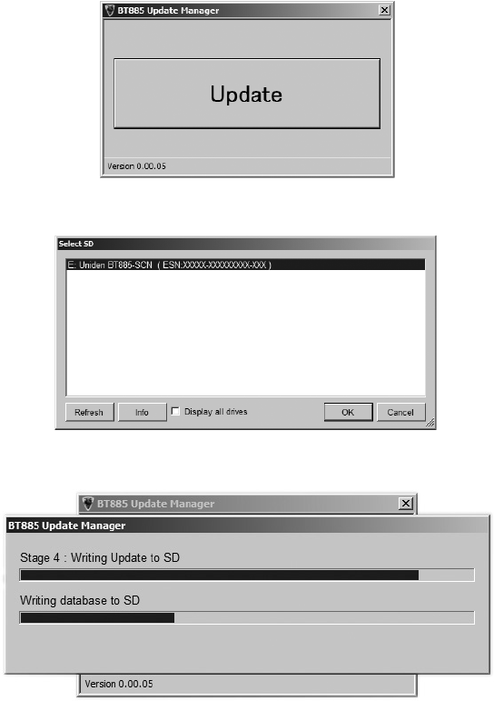
E-27
3. Insert the SD card into your PC’s SD card slot. If your PC does not
have an SD card slot, insert it into an SD to USB converter (not
included) and then into your PC’s USB slot. An Autoplay dialog
box displays. Close it.
4. Search for BT885_Update_Manager on your system. Select it,
then click Update on the screen that displays.
5. The Select SD screen displays. Look for Uniden BT885-SCN and
select it. Click OK.
6. The BTOM updates the SD card, showing progress bars through
all the stages.
7. Close the screen when update is completed.
8. Remove the SD card from your PC and insert it back into your
radio. Turn the radio back on; LOAD ashes on the screen while the

E-28
database is being updated. When the update is complete, SCAN
displays.
PREVENTIVE MAINTENANCE
Every six months:
1. Check the SWR.
2. Be sure all electrical connections are tight.
3. Inspect antenna coaxial cable for wear or breaks in shielding.
4. Be sure all screws and mounting hardware are tight.
MAINTENANCE
The BearTracker 885 is designed to give you years of trouble-free service.
There are no user-serviceable parts inside. It requires no maintenance
except replacing the inline fuse in the fuse holder of the DC power cord.
To replace a blown fuse:
1. Press ends of the fuse holder together. Twist to open. Carefully
separate the two pieces.
2. Remove the fuse and inspect. If blown, replace with the same
type 6-amp fuse.
Use only the fuse specied for your BearTracker 885. Failure to
do so may void your warranty.
TROUBLESHOOTING
In the event of system malfunction, perform the following procedures:
Problem Suggestion
Unit does not power up Check power cord connections.
Check fuse.
Check vehicle electrical system.
No reception Check microphone connection.
Set CB/PA to CB.
Check VOLUME and SQUELCH.
Check antenna.
Check antenna connection.
Adjust RF Gain.

E-29
Problem Suggestion
Poor Reception Check VOLUME and SQUELCH.
Be sure antenna SWR is normal.
Adjust RF Gain.
No Transmission Set CB/PA/WX|WX.ALT to CB.
Check microphone connection.
Adjust MIC Gain.
Low Transmission Adjust MIC Gain.
Unit does not work as well as
previously.
Turn the power o then back on. The channels
will reset.
No GPS Signal Check RJ45 jack connections.
Examine GPS module and look for any
damage.
If you do not get satisfactory results after performing these checks, visit
the Uniden website (www.uniden.com) for troubleshooting and FAQ
information.
SERVICING YOUR TRANSCEIVER
It is the user's responsibility to see that this radio is operating at all times
in accordance with the FCC Citizens Radio Service regulations. We highly
recommend that you consult a qualified radio/telephone technician for
servicing and aligning this CB radio product.
When ordering parts, be sure to specify the correct model
number and serial number of the unit.
SPECIFICATIONS
GENERAL
Channel: CB: 40 AM (4W)
Scanner: FM Only
Frequency Range: CB : 26.965 ~ 27.405 MHz
SCN: 25 ~ 960 MHz
WX : 162.400 - 162.550 MHz
Microphone 600 ohms, Dynamic Type
Internal Speaker 16 ohms, 5W Max
Emission Emission AM/USB/LSB
Frequency Control: PLL Synthesizer

E-30
Antenna Impedance: 50 ohms
Power Input: 13.8VDC
Current Drain
No Modulation: 1300 mA Nom.
Max. Modulation: 1900 mA Nom.
Operating Temperature: CB: -22°F to 140°F (-30°C to 60°C)
Scanner/GPS: 14°F to 140°F
(-10°C to 60°C)
Storage Temperature: –40°F to 158°F
–40°C to 70°C
Accessories: DC Power Cord
Noise Cancelling Microphone
Microphone Hanger
Mounting Bracket
Owner’s Manual
Part 95 Subpart D (FCC Rules)
Size (W x H x D): 7.28 in. W x 8.1 in. H x 2.2 in. D
(without knobs and jacks)
(185 mm W x 205 mm H x 56 mm D)
Weight: Approx 63.5 oz (1.8 kg.)
CB TRANSMITTER
Output Power: AM: 4 watts; USB/LSB 12 W PEP SSB
Hum and Noise Ratio at –47dBm 35 dB
Frequency Tolerance: ±0.002%
Modulation Percentage (Peak): 100%
Spurious Rejection: -70 dBc
Output Impedance: 50 ohm, unbalanced
Unwanted Sideband -55 db
CB RECEIVER
Sensitivity at 10 dB S/N: –113 dBm
Sensitivity at 500 mW Audio Output: 0.5 µV
Squelch Threshold: 0.5 µV
Antenna Impedance: 50 ohms
Squelch Tight: 1000 µV
Signal Meter S-9: 100 µV
Audio Output Power (max.): 5 watts
Audio Output (10% Distortion): 2.5 watts
Clarier Range 1.5 kHz
E-31
Adjacent Channel Rejection: 55 dB
Image Rejection: 65 dB Nom.
Internal Speaker Impedance: 16 ohms
External Speaker Impedance: 8 ohms
PUBLIC ADDRESS
Output Power at 10% Distortion: 4 watts
Microphone Sensitivity @1kHz 10%
Distortion:
5 mV Nom.
GPS
Acquisition Time
(GPS anechoic box input: –103 dB) 30 sec Nom.
Specifications shown are typical and subject to change without notice.
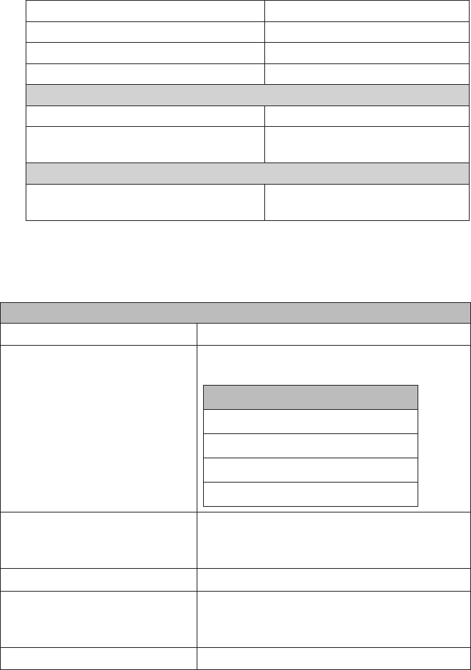
SCANNER
GENERAL
Band Coverage 4
Frequency Range Conventional Mode or Trunking Mode
NFM or FM
Band Frequency (MHz)
25.0000-54.000
137.000-225.0000
320.0000-512.0000
758.0000-960.0000
Memory System No programming required; preset program.
Factory programmed to microSD card for all
known radio systems in US and Canada
Step Size Auto (5/6.25 kHz)
GPS Function GGA (Global Positioning System Fixed Data)
RMC (Recommended Minimum Specic
GNSS Data)
WX Alert 1050Hz

E-32
Trunking System Motorola System (Type I, II, IIi, X2-TDMA)
EDACS System (FM/NFM)
LTR System
APCO System [ASTRO IMBE, ASTRO 25.P25
AMBE(HDQPSK)]
Heterodyne System
1st Heterodyne
25.000 ~ 225.000 MHz Upper Heterodyne 1st IF 380.75 MHz
320.000 ~ 511.995 MHz Upper Heterodyne 1st IF 265.55 MHz
758.000 ~ 805.995 MHz Lower Heterodyne 1st IF 265.55 MHz
806.000 ~ 960.000 MHz Lower Heterodyne 1st IF 380.75 MHz
2nd Heterodyne
25.000 ~ 225.000 MHz Lower Heterodyne 2nd IF10.800 MHz
320.000 ~ 805.995 MHz Upper Heterodyne 2nd IF 10.800 MHz
806.000 ~ 960.000 MHz Lower Heterodyne 2nd IF 10.800 MHz
3rd Heterodyne
All Bands Lower Heterodyne 3rd IF450 MHz
Filter
380.75 MHz SAW lter 1st IF
265.55 MHz SAW lter 1st IF
10.8 MHz Ceramic Filter (BW ±75kHz) 2nd IF
450 kHz Ceramic Filter (BW ±75kHz) 3rd IF
Weather Channels: 7 Channels
Scan Rate: 85 channels/second
Scan Delay: 2 seconds
Antenna: 50 ohms (Impedance)
CTCSS FREQUENCIES
The scanner can detect the following 50 CTCSS frequencies.
67.0Hz 94.8Hz 131.8Hz 171.3Hz 203.5Hz
69.3Hz 97.4Hz 136.5Hz 173.8Hz 206.5Hz
71.9Hz 100.0Hz 141.3Hz 177.3Hz 210.7Hz

E-33
74.4Hz 103.5Hz 146.2Hz 179.9Hz 218.1Hz
77.0Hz 107.2Hz 151.4Hz 183.5Hz 225.7Hz
79.7Hz 110.9Hz 156.7Hz 186.2Hz 229.1Hz
82.5Hz 114.8Hz 159.8Hz 189.9Hz 233.6Hz
85.4Hz 118.8Hz 162.2Hz 192.8Hz 241.8Hz
88.5Hz 123.0Hz 165.5Hz 196.6Hz 250.3Hz
91.5Hz 127.3Hz 167.9Hz 199.5Hz 254.1Hz
DCS CODES
The scanner can detect the following hexadecimal DCS codes.
023 025 026 031 032 036 043 047 051 053 054 065 071 072
073 074 114 115 116 122 125 131 132 134 143 145 152 155
156 162 165 172 174 205 212 223 225 226 243 244 245 246
251 252 255 261 263 265 266 271 274 306 311 315 325 331
332 343 346 351 356 364 365 371 411 412 413 423 431 432
445 446 452 454 455 462 532 445 446 452 454 455 462 464
465 466 503 506 516 523 526 532 546 565 606 612 624 627
631 632 654 662 665 703 712 723 731 732 734 743 754
006 007 015 017 021 050 141 214
Sensitivity (12dB SINAD) Nominal
VHF Low 1 Band
NFM 25.0050 MHz 0.3 μV
NFM 40.8400 MHz 0.3 μV
FM 53.9800 MHz 0.3 μV
VHF High 1 Band
NFM 138.1500 MHz 0.4 μV
NFM 161.9850 MHz 0.3 μV
NFM 173.2250 MHz 0.3 μV
NFM 197.4500 MHz 0.3 uV
NFM 216.0200 MHz 0.3 uV
UHF Band
NFM 325.0500 MHz 0.3 μV
NFM 406.8750 MHz 0.3 μV

E-34
NFM 511.9125 MHz 0.3 μV
Public Service Band
NFM 758.0125 MHz 0.3 μV
NFM 806.0000 MHz 0.3 μV
NFM 857.1500 MHz 0.3 μV
NFM 954.9125 MHz 0.4 μV
Threshold Squelch (Manual)
VHF Low 1 Band
NFM 40.8400 MHz 0.2 μV
FM 53.9800 MHz 0.2 μV
VHF High 1 Band
NFM 127.1750 MHz 0.2 μV
NFM 161.9850 MHz 0.2 μV
NFM 272.9500 MHz 0.2 μV
UHF Band
NFM 406.8750 MHz 0.2 μV
Public Service Band
NFM 758.0125 MHz 0.3 μV
NFM 857.1500 MHz 0.3 μV
Tight Squelch (Manual) (S+N)/N
VHF Low 1 Band
NFM 40.8400 MHz 17 dB
FM 53.9800 MHz 22 dB
VHF High 1 Band
NFM 161.9850 MHz 17 dB
NFM 173.2250 MHz 17 dB
NFM 216.0200 MHz 17 dB
UHF Band
NFM 406.8750 MHz 18 dB
Public Service Band
NFM 758.0125 MHz 17 dB
NFM 857.1500 MHz 18 dB

E-35
Hum and Noise
VHF Low 1 Band
NFM 40.8400 MHz 43 dB
FM 53.9800 MHz 47 dB
VHF High 1 Band
NFM 161.9850 MHz 41 dB
NFM 173.2250 MHz 42 dB
NFM 216.0200 MHz 42 dB
UHF Band
NFM 406.8750 MHz 41 dB
Public Service Band
NFM 758.0125 MHz 42 dB
NFM 857.1500 MHz 42 dB
Audio Frequency Response –6 dB
NFM 40.8400 MHz Low: 330 Hz
High: 2100 Hz
FM 53.9800 MHz Low: 340 Hz
High: 2200 Hz
Audio Output Power
NFM 40.8400 MHz 4 W
FM 53.9800 MHz 4 W
Distortionr
NFM 40.8400 MHz 1.2%
FM 53.9800 MHz 1.8%
IF Rejection
IF = 380.75 Hz FM 84 dB
Specifications shown are typical and subject to change without notice.
FCC PART 15/IC COMPLIANCE
FCC COMPLIANCE
This device complies with Part 15 of the FCC rules. Operation is subject
to the following two conditions: (1) This device may not cause harmful
E-36
interference, and (2) this device must accept any interference received,
including interference that may cause undesired operation.
Changes or modifications not expressly approved by the party
responsible for compliance could void your authority to operate the
equipment.
Avis de conformité à la FCC : Ce dispositif a été testé et s’avère
conforme à l’article 15 des règlements de la Commission fédérale des
communications (FCC). Ce dispositif est soumis aux conditions suivantes:
1) Ce dispositif ne doit pas causer d’interférences nuisibles et; 2) Il doit
pouvoir supporter les parasites qu’il reçoit, incluant les parasites pouvant
nuire à son fonctionnement.
Tout changement ou modification non approuvé expressément par
la partie responsable pourrait annuler le droit à l’utilisateur de faire
fonctionner cet équipement.
IC COMPLIANCE
This device complies with Industry Canada license-exempt RSS
standard(s). Operation is subject to the following two conditions: (1) this
device may not cause interference, and (2) this device must accept any
interference, including interference that may cause undesired operation
of the device. In Canada, a radio license must be obtained prior to
possession and use of this scanner receiver.
Changes or modifications not expressly approved by the party
responsible for compliance could void your authority to operate the
equipment.
Cet appareil est conforme aux normes RSS exemptes de licences
d’Industrie Canada. Son fonctionnement est soumis aux deux conditions
suivantes : (1) cet appareil ne doit pas causer d’interférences nuisibles
et (2), il doit pouvoir accepter les interférences, incluant celles pouvant
nuire à son fonctionnement normal. Au Canada, l’obtention d’une licence
est nécessaire avant d’acheter et de faire fonctionner ce scanneur.

E-37
Tout changement ou modification non approuvé expressément par
la partie responsable pourrait annuler le droit à l’utilisateur de faire
fonctionner cet équipement.
ONE-YEAR LIMITED WARRANTY
Important: Evidence of original purchase is required for warranty service.
WARRANTOR: UNIDEN AMERICA CORPORATION (“Uniden”)
ELEMENTS OF WARRANTY: Uniden warrants, for one year, to the original retail owner,
this Uniden Product to be free from defects in materials and craftsmanship with only the
limitations or exclusions set out below.
WARRANTY DURATION: This warranty to the original user shall terminate and be of
no further effect one year after the date of original retail sale. The warranty is invalid if
the Product is (A) damaged or not maintained as reasonable or necessary, (B) modified,
altered, or used as part of any conversion kits, subassemblies, or any configurations
not sold by Uniden, (C) improperly installed, (D) serviced or repaired by someone other
than an authorized Uniden service center for a defect or malfunction covered by this
warranty, (E) used in any conjunction with equipment or parts or as part of any system
not manufactured by Uniden, or (F) installed or programmed by anyone other than as
detailed by the owner’s manual for this product.
STATEMENT OF REMEDY: In the event that the product does not conform to this
warranty at any time while this warranty is in effect, warrantor will either, at its option,
repair or replace the defective unit and return it to you without charge for parts,
service, or any other cost (except shipping and handling) incurred by warrantor or
its representatives in connection with the performance of this warranty. Warrantor,
at its option, may replace the unit with a new or refurbished unit. THE LIMITED
WARRANTY SET FORTH ABOVE IS THE SOLE AND ENTIRE WARRANTY PERTAINING TO THE
PRODUCT AND IS IN LIEU OF AND EXCLUDES ALL OTHER WARRANTIES OF ANY NATURE
WHATSOEVER, WHETHER EXPRESS, IMPLIED OR ARISING BY OPERATION OF LAW,
INCLUDING, BUT NOT LIMITED TO ANY IMPLIED WARRANTIES OF MERCHANTABILITY
OR FITNESS FOR A PARTICULAR PURPOSE. THIS WARRANTY DOES NOT COVER OR
PROVIDE FOR THE REIMBURSEMENT OR PAYMENT OF INCIDENTAL OR CONSEQUENTIAL
DAMAGES.
Some states do not allow this exclusion or limitation of incidental or consequential
damages so the above limitation or exclusion may not apply to you.
E-38
LEGAL REMEDIES: This warranty gives you specific legal rights, and you may also have
other rights which vary from state to state. This warranty is void outside the United
States of America.
PROCEDURE FOR OBTAINING PERFORMANCE OF WARRANTY: If, after following the
instructions in the owner’s manual you are certain that the Product is defective, pack the
Product carefully (preferably in its original packaging). The Product should include all
parts and accessories originally packaged with the Product. Include evidence of original
purchase and a note describing the defect that has caused you to return it. The Product
should be shipped freight prepaid, by traceable means, to warrantor at:
Uniden America Service
C/O Saddle Creek
743 Henrietta Creek Rd., Suite 100
Roanoke, TX 76262

E-39
RADIO CODE DEFINITIONS
The following list contains common “10-Codes” used by CB radio
operators for faster communication and better understanding.
Code Meaning Code Meaning
10-1 Received poorly 10-34 Trouble at this station
10-2 Receiving well 10-35 Condential information
10-3 Stop transmitting 10-36 Correct time is
10-4 OK, message received 10-37 Wrecker needed at
10-5 Relay message 10-38 Ambulance needed at
10-6 Busy, stand by 10-39 Your message is delivered
10-7 Out of service, leaving air 10-41 Please turn to channel
10-8 In service, subject to call 10-42 Trac accident at
10-9 Repeat message 10-43 Trac tie up at
10-10 Transmission completed,
standing by
10-44 I have a message for you
10-11 Talking too rapidly 10-45 All units within range
please
report
10-12 Visitors present 10-50 Break channel
10-13 Advise Weather/ Road
conditions
10-60 What is next message
number
10-16 Make pickup at 10-62 Unable to copy, use phone
10-17 Urgent business 10-63 Net directed to
10-18 Anything for us? 10-64 Net clear
10-19 Nothing for you, return to
base
10-65 Awaiting your next
message/assignment
10-20 My location is 10-67 All units comply
10-21 Call by telephone 10-70 Fire at
10-22 Report in person to 10-71 Proceed with transmission
in sequence
10-23 Stand by 10-77 Negative contact
10-24 Completed last assignment 10-81 Reserve hotel room for
10-25 Can you contact 10-82 Reserve room for

E-40
Code Meaning Code Meaning
10-26 Disregard last information 10-84 My telephone number is
10-27 I am moving to channel 10-85 My address is
10-28 Identify your station 10-91 Talk closer to microphone
10-29 Time is up for contact 10-93 Check my frequency on
this channel
10-30 Does not conform to FCC
rules
10-94 Please give me a long
count
10-32 I will give you a radio check 10-99 Mission completed, all
units secure
10-33 EMERGENCY TRAFFIC 10-200 Police needed at