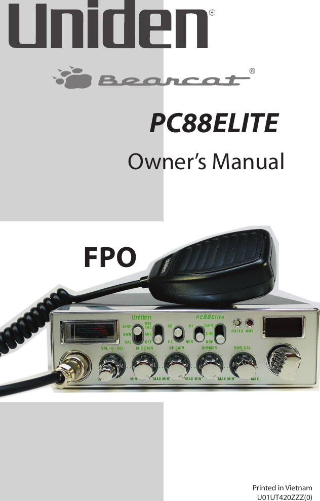
Uniden America UT420 AM 4W, Mobile CB Station Transceiver User Manual 1 Uniden EMC Report R0 1

Uniden America Corporation AM 4W, Mobile CB Station Transceiver 1 Uniden EMC Report R0 1

User Manual

 Test Report S/N:   45461429 R1.0 Test Report Issue Date:   2 March 2018   ©2016 Celltech Labs Inc.  This document is not to be reproduced in whole or in part without the expressed written permission of Celltech Labs Inc.   Page 61 of 80   EXHIBIT 11 – USER’S MANUAL  See attached
Owner’s ManualPrinted in VietnamU01UT420ZZZ(0)®PC88ELITEFPO
 © 2018 Uniden America CorporationUniden is a registered trademark of Uniden America Corporation.Bearcat is a registered trademark of Uniden America Corporation. Features, specifications, and availability of optional accessories are all subject to change without notice.
CONTENTSINTRODUCTION .......................................................................... 5SAFETY NOTICE ............................................................................................. 5CB LICENSE REQUIREMENT ......................................................................... 5UNPACKING ................................................................................................... 5FEATURES ...................................................................................................... 6EMERGENCY OPERATION ............................................................................ 6CONTROLS AND FUNCTIONS .................................................... 7INSTALLATION ............................................................................ 8MOBILE STATION INSTALLATION ................................................................ 8MOBILE STATION ANTENNA ........................................................................ 9MARINE INSTALLATION ............................................................................... 9CONNECTING THE POWER CORDS .............................................................. 9GROUND INFORMATION ............................................................................ 10Negative Ground System .......................................................................... 10USING YOUR PC88ELITE ............................................................................. 10TURN PC88ELITE ON/OFF .......................................................................... 10CB MODE ...................................................................................................... 10Basic Settings ............................................................................................ 10PA MODE ...................................................................................................... 11TO TRANSMIT ............................................................................ 11MULTI-FUNCTION METER ........................................................ 12PREVENTIVE MAINTENANCE .................................................. 12MAINTENANCE ......................................................................... 13TROUBLESHOOTING ................................................................ 13SERVICING YOUR TRANSCEIVER  ........................................... 14SPECIFICATIONS ....................................................................... 14
CHANNEL FREQUENCY LIST .................................................... 15FCC PART 15/ICC COMPLIANCE .............................................. 17FCC COMPLIANCE ....................................................................................... 17IC COMPLIANCE .......................................................................................... 17ONE-YEAR EXTENDED WARRANTY ........................................ 18RADIO CODE DEFINITIONS  ..................................................... 2010-CODES ..................................................................................................... 20
5PC88ELITEPROFESSIONAL MOBILE CB RADIOINTRODUCTIONYour Uniden PC88Elite is a high-quality communications device designed for use in the Citizens Band Radio Service. It will operate on any of the 40 AM frequencies authorized by the Federal Communications Commission (FCC).SAFETY NOTICEThe antenna used for this transceiver must be properly installed and maintained and must provide a separation distance of at least 17.32 inches (44 cm) from all persons and must not be collocated or operated in conjunction with any other antenna or transmitter.  Never transmit if any person is closer than the specified distance to the antenna. Note that Uniden does not specify or supply any antenna with this radio. While a 0 dBi gain antenna is normal for a typical installation, the above limit applies to any antenna with up to 3 dBi gain.CB LICENSE REQUIREMENTU.S. users no longer need to apply for a license to use a CB radio. However, CB radio is still considered a “license by rule” service. This means that, while the FCC permits CB station operation without station identification, station operators are still required to comply with the Communications Act and with the rules of CB Radio Service. (For more information on U.S. radio rules, visit the FCC website at www.fcc.gov.)UNPACKINGCarefully unpack your PC88Elite and check the contents against this list: PC88Elite CB 2-way mobile radio Microphone
6 Mounting Bracket Kit DC Power Cord User’s Guide Part 95 Subpart D (FCC Rules)If any items are missing or damaged, contact your place of purchase immediately.FEATURES Mic Gain Control- Adjust sensitivity for optimal transmission quality RF Gain Control - Control receiving sensitivity to pull in or block out faint signals PA/CB Switch - Easily switch between CB transmissions and PA output Backlit Controls and Display - Simplies night operation Direct tune Channels 9 and 19 - Access emergency channels quickly and easily with a single switch 40 Channel Operations- Operates on all 40 standard CB channels Channel Indicator - Easily see the current channel Variable Dimmer Control - Control the backlight brightness High/Normal Tone - Select a high or normal tone Analog S/RF/SWR/ meter - Built-in Power and SWR metersEMERGENCY OPERATION1.  Set the switch to CH9 or turn Channel Selector knob to Channel 9.2.  Press the microphone PTT switch and speak clearly.3.  If there is no response, select an active channel and ask that party to relay your emergency broadcast on Channel 9.All channels except Channel 9 may be used for normal communication. Channel 9 is reserved by the FCC for emergency communication involving the immediate safety of individuals or protection of property. Channel 9 may also be used to render assistance to others.This is an FCC rule and applies to all operators of CB radios.
7CONTROLS AND FUNCTIONS1.  4 pole Microphone Socket2.  ON OFF - VOLUME: Turns radio on or o; adjusts speaker volume.3.  SQUELCH: Reduces background noise when there is no incoming signal.4.  MIC GAIN: Adjusts microphone sensitivity for transmission and PA mode.5.  RF GAIN: Improves reception in strong signal areas.6.  DIMMER: Fine tunes the backlight intensity.7.  SWR CAL: Calibrates the meter for Standing Wave Ratio (SWR) measurements.8.  Channel knob: Selects channel.9.  Channel Display: Displays current channel selection.10.  RX/TX LED/ANT LED: Red-transmitting; green-receiving.  ANT LED: Indicates a high SWR condition in antenna system. Check antenna, cable, and connections.11.  CH9/CH19/NOR switch: Tunes to emergency channels 9 or 19, or normal (non-emergency) channels.12.  Tone switch. Select High or Normal tone.13.  CB/PA switch: Selects CB (Citizen’s Band) or PA (Public Address). Do not use PA function unless an external speaker is connected.14.  NB/ANL/ANL/OFF switch: Reduces external noise and interference from vehicle ignition systems.
815.  S/RF/SWR/ CAL switch: Selects meter function. S/RF - normal; SWR and CAL are for SWR measurements only. See page 12 for calibration procedures.16.  Multi-function meter: Measures SWR, RF and S signal strength.17.  POWER connector: Connects DC power to transceiver.18.  EXT. SP. jack: Connects optional 8-ohm 4-watt speaker to remotely monitor the receiver.When the external speaker is plugged in, the internal speaker is o.19.  PA SP. jack: Connects external 8-ohm, 4-watt speaker.To prevent acoustic feedback, separate the microphone from the speaker when operating the PA at high output levels.20.  Antenna socket: Connects antenna cable to transceiver.INSTALLATIONMOBILE STATION INSTALLATIONPlan the location of the transceiver and microphone bracket before beginning installation.1.  Select a location that is convenient for operating the radio, but does not interfere with the driver or passenger.2.  Install bracket with self-tapping screws provided.3.  Connect wiring. (See instructions for Connecting the Power Cords.)4.  Attach the microphone bracket to the side of the radio.5.  Attach radio to bracket.
9MOBILE STATION ANTENNABecause the maximum power output of the transmitter is limited by the FCC, the quality of your antenna is very important. To achieve the maximum transmission distance, we strongly recommend that you install only a high quality antenna. You have just purchased a superior transceiver - don’t diminish its performance by installing an inferior antenna.Only a properly matched antenna system will allow maximum power transfer from the 50 ohm transmission line to the radiating element.Your Uniden dealer is qualified to help you select the proper antenna for your requirements. A whip style antenna may be used for automobile installation.A short “loaded” whip antenna is easier to install on an automobile. However, the efficiency of the short whip antenna is less than that of a full quarter-wave whip antenna.MARINE INSTALLATIONConsult your dealer for information regarding marine installation. It is important to adequately ground the system and to prevent electrolysis between the fittings in the hull and the water.CONNECTING THE POWER CORDSUniden recommends connecting the power lead to the Ignition Switch Accessory Terminal. This way, the transceiver is automatically turned off when the ignition switch is turned off. As an alternative, the power cord may be connected to an available terminal on the fuse block or to a point in the wiring harness. However, take care to prevent a short circuit. If in doubt, contact your vehicle dealer for information. This transceiver may be installed and used in any 12-volt DC negative or positive ground system vehicle.
10GROUND INFORMATIONMost newer U.S. and foreign made cars and small trucks use a negative ground system. Some older cars, and some new large trucks, use a positive ground system.With a negative ground system, the negative (-) battery terminal is usually connected to the vehicle motor block. If you cannot determine the polarity system of your vehicle, contact your vehicle dealer for information.Negative Ground SystemFor negative ground systems, connect the red DC power cord from the transceiver to the positive (+) battery  terminal or other convenient point.Then connect the black power cord to the vehicle chassis or negative (-) battery terminal.USING YOUR PC88ELITERefer to the PC88Elite call out diagram on page 7 for the referenced switches and knobs. TURN PC88ELITE ON/OFFTurn the VOL knob clockwise until the unit turns on and the display backlight turns on.Turn the VOL knob counter-clockwise to turn the unit off.CB MODEBe sure that the power source, antenna, and micropone are properly connected before proceeding.Basic Settings1.  Turn the unit on. Set the volume to a comfortable level.2.  Set switch to CB.
113.  Turn the CH knob to select a CB channel.4.  Set noise limitations switch to NB/ANL.5.  Adjust squelch.•  Adjust outer Squelch knob fully clockwise so only strong signals can get through.   •  Adjust outer Squelch knob fully counter-clockwise until you hear a hiss. Everything gets through - noise, weak signals, and strong signals.•  Slowly adjust outer Squelch knob back clockwise until the hiss stops. Only clearer signals get through.Set SQUELCH only when the radio is not receiving a strong signal.6.  Adjust RF GAIN knob to set RF Gain sensitivity.7.  Adjust MIC GAIN knob to set microphone sensitivity.8.  Set meter switch to S/RF.PA MODEUsing the PA mode requires an optional speaker. 1.  Switch to PA. 2.  Press and hold PTT to speak.3.  Release when nished. To prevent acoustic feedback, separate the microphone from the speaker when operating the PA at high output levels.If you are in PA mode but not pressing PTT, the radio receives CB transmissions and transmits them through the PA speaker. You cannot respond to the transmission.TO TRANSMITPerform a voltage Standing Wave Ratio (SWR) measurement prior to using the transmitter. An SWR ratio in excess of 2:1 may damage the transmitter.Be sure to read and understand Part 95, FCC Rules and Regulations before operating your transmitter.1.  Select a channel.2.  Adjust MIC GAIN.3.  When the channel is clear, press the microphone PTT and speak.
12MULTI-FUNCTION METERSWR Meter: Measures the standing wave ratio (SWR) of the antenna, received signal strength, or RF output. Use this meter to check the antenna system or to adjust your antenna to the proper length.To Measure SWR:1.  Set the meter switch to CAL.2.  Press and hold microphone PTT switch (Transmit).3.  Calibrate meter with SWR knob by adjusting the needle to the ▼ mark.4.  Move the meter switch to the SWR position while pressing the microphone PTT switch. Measure the SWR from the meter reading.5.  Release the PTT switch.A reading following two is acceptable. Higher readings indicate a problem in the antenna system. Problems may be caused by humidity, vibration, or corrosion. Check both ends of the coaxial cable connector. Also check for damage to the cable or antenna.RF Meter: Measures RF Output Power for transmitter. To use, set the meter switch at S/RF. Press microphone PTT switch to read transmitting power.S-Meter: Measures incoming signal strength. To use, set the meter switch at S/RF. The meter swings to indicate signal strength.i.e. S 3, S 5, S 7 . . .PREVENTIVE MAINTENANCEEvery six months:1.  Check the Standing Wave Ratio (SWR).2.  Be sure all electrical connections are tight.3.  Inspect antenna coaxial cable for wear or breaks in shielding.4.  Be sure all screws and mounting hardware are tight.
13MAINTENANCEThe PC88Elite is designed to give you years of trouble-free service. There are no user-serviceable parts inside. Except for the fuse in the DC power cord, no maintenance is required.To replace a blown fuse:1.  Press ends of the fuse holder together. Twist to open.2.  Carefully separate the two pieces.3.  Remove the fuse and inspect. If blown, replace with the same type fuse. Use only the fuse specied for your PC88Elite. Failure to do so may void your warranty.TROUBLESHOOTINGIn the event of system malfunction, perform the following procedures: Problem SuggestionUnit does not power up Check the ignition key position.Check power cord connections. Check fuse. Check vehicle electrical system.No reception Check microphone connection. Set CB/PA to CB. Check VOL and SQ. Check antenna. Check antenna connection. Adjust RF Gain. Poor Reception Check VOL and SQ. Be sure antenna SWR is normal.Adjust RF Gain.No Transmission Set CB/PA switch to CB. Check microphone connection.Adjust MIC Gain. Low Transmission Be sure antenna SWR is normal.Adjust MIC Gain. Calibration does not move the meter needle to the left sideAdjust the antenna height.Check all antenna connections.If you do not get satisfactory results after performing these checks, visit ww.uniden.com for troubleshooting information and FAQs.
14SERVICING YOUR TRANSCEIVER It is the user’s responsibility to see that this radio is operating at all times in accordance with the FCC Citizens Radio Service regulations. We highly recommend that you consult a qualified radio/telephone technician for servicing and aligning this CB radio product. When ordering parts, be sure to specify the correct model number and serial number of the unit. SPECIFICATIONSGENERALChannel: 40CB Frequency Range: 26.965 - 27.405 MHzFrequency Control: Phase Locked Loop (PLL) synthesizerFrequency Tolerance: ±0.002%Operating Temperature: CB:  -22°F to 140°F (-30°C to 60°C)Microphone: Plug-in type; 600 ohms dynamicInput: 13.8VDCCurrent Drain: TX:  AM Full Modulation: 2.1A (max)RX:  Squelched, 0.4 A; with maximum audio  output, 1.2A (nominal)Size (W x D x H):  7-9/32 in. x 8-57/64 in. x 2-13/64 in. (without knobs and jacks)Weight: 4 lb, 3 oz with microphoneAntenna Connector: M TypeMeter: Illuminated: indicates relative power out-put and received signal strength SWR.Accessories:  DC Power Cord Microphone Microphone HangerMounting BracketTRANSMITTERPower Output: 4 wattsModulation:  High- and Low-Level, Class B amplitude modulation
15Frequency Response: 300 - 3000 HzOutput Impedance: 50 ohm, unbalancedRECEIVERSensitivity at 10 dB (S+N)/N: <1 µV for 10 dB, (S+N)/NSelectivity: 6 dB @ 7 kHz; 60 dB @ 10 kHzImage Rejection: 80 dB typicalAdjacent-CH Rejection: 60 dB typicalIF Frequencies: Double Conversion: 1st: 10,695 MHz2nd: 455 kHzAutomatic Gain Control: Less than 10 dB change in audio output for inputs from 10 to 50,000 µV.RF Gain Control: Adjustable for optimum signal receptionNoise Blanker: RF typeSquelch: Adjustable; threshold <1 µVAudio Output Power: 4 WattsFrequency Response: 300 to 3000 HzDistortion: Less than 7% at 3 Watts, 1000 HzInternal Speaker: 8 ohms, roundExternal Speaker (not supplied): 8 ohms; disables internal speaker when connectedPA SYSTEMPower Output: 4 Watts into external speakerExternal Speaker for PA Speaker (not supplied):8 ohms when CB/PA switch in in PA. The PA also monitors the receiver; separate jack provided. Specications shown are typical and subject to change without notice. CHANNEL FREQUENCY LISTCHANNELNUMBERFREQUENCY (MHz) RX TX1 26.965 O O2 26.975 O O3 26.985 O O4 27.005 O O5 27.015 O O
16CHANNELNUMBERFREQUENCY (MHz) RX TX6 27.025 O O7 27.035 O O5 27.055 O O9 27.065 O O10 27.075 O O11 27.085 O O12 27.105 O O13 27.115 O O14 27.125 O O15 27.135 O O16 27.155 O O17 27.165 O O18 27.175 O O19 27.185 O O20 27.205 O O21 27.215 O O22 27.225 O O23 27.255 O O24 27.235 O O25 27.245 O O26 27.265 O O27 27.275 O O28 27.285 O O29 27.295 O O30 27.305 O O31 27.315 O O32 27.325 O O33 27.335 O O34 27.345 O O35 27.355 O O36 27.365 O O
17CHANNELNUMBERFREQUENCY (MHz) RX TX37 37.375 O O38 27.385 O O39 27.395 O O40 27.405 O OEmergency channels 9 and 19 are direct tune channels and do not need to be set through the Channel knob.FCC PART 15/ICC COMPLIANCEFCC COMPLIANCEThis device complies with Part 15 of the FCC rules. Operation is subject to the following two conditions: (1) This device may not cause harmful interference, and (2) this device must accept any interference received, including interference that may cause undesired operation.Changes or modifications not expressly approved by the party responsible for compliance could void your authority to operate the equipment.Avis de conformité à la FCC : Ce dispositif a été testé et s’avère conforme à l’article 15 des règlements de la Commission fédérale des communications (FCC). Ce dispositif est soumis aux conditions suivantes: 1) Ce dispositif ne doit pas causer d’interférences nuisibles et; 2) Il doit pouvoir supporter les parasites qu’il reçoit, incluant les parasites pouvant nuire à son fonctionnement.Tout changement ou modification non approuvé expressément par la partie responsable pourrait annuler le droit à l’utilisateur de faire fonctionner cet équipement.IC COMPLIANCEThis device complies with Industry Canada license-exempt RSS standard(s). Operation is subject to the following two conditions: (1) this device may not cause interference, and (2) this device must accept any
18interference, including interference that may cause undesired operation of the device.Changes or modifications not expressly approved by the party responsible for compliance could void your authority to operate the equipment.Cet appareil est conforme aux normes RSS exemptes de licences d’Industrie Canada. Son fonctionnement est soumis aux deux conditions suivantes : (1) cet appareil ne doit pas causer d’interférences nuisibles et (2), il doit pouvoir accepter les interférences, incluant celles pouvant nuire à son fonctionnement normal.Tout changement ou modification non approuvé expressément par la partie responsable pourrait annuler le droit à l’utilisateur de faire fonctionner cet équipement.ONE-YEAR EXTENDED WARRANTYImportant: Evidence of original purchase is required for warranty service.WARRANTOR: UNIDEN AMERICA CORPORATION (“Uniden”)ELEMENTS OF WARRANTY: Uniden warrants, for one year, to the original retail owner, this Uniden Product to be free from defects in materials and craftsmanship with only the limitations or exclusions set out below.WARRANTY DURATION: This warranty to the original user shall terminate and be of no further effect one year after the date of original retail sale. The warranty is invalid if the Product is (A) damaged or not maintained as reasonable or necessary, (B) modified, altered, or used as part of any conversion kits, subassemblies, or any configurations not sold by Uniden, (C) improperly installed, D) serviced or repaired by someone other than an authorized Uniden service center for a defect or malfunction covered by this warranty, (E) used in any conjunction with equipment or parts or as part of any system not manufactured by Uniden, or (F) installed or programmed by anyone other than as detailed by the owner’s manual for this product.
19STATEMENT OF REMEDY: In the event that the product does not conform to this warranty at any time while this warranty is in effect, warrantor will either, at its option, repair or replace the defective unit and return it to you without charge for parts, service, or any other cost (except shipping and handling) incurred by warrantor or its representatives in connection with the performance of this warranty. Warrantor, at its option, may replace the unit with a new or refurbished unit. THE LIMITED WARRANTY SET FORTH ABOVE IS THE SOLE AND ENTIRE WARRANTY PERTAINING TO THE PRODUCT AND IS IN LIEU OF AND EXCLUDES ALL OTHER WARRANTIES OF ANY NATURE WHATSOEVER, WHETHER EXPRESS, IMPLIED OR ARISING BY OPERATION OF LAW, INCLUDING, BUT NOT LIMITED TO ANY IMPLIED WARRANTIES OF MERCHANTABILITY OR FITNESS FOR A PARTICULAR PURPOSE. THIS WARRANTY DOES NOT COVER OR PROVIDE FOR THE REIMBURSEMENT ORPAYMENT OF INCIDENTAL OR CONSEQUENTIAL DAMAGES. Some states do not allow this exclusion or limitation of incidental or consequential damages so the above limitation or exclusion may not apply to you.LEGAL REMEDIES: This warranty gives you specific legal rights, and you may also have other rights which vary from state to state. This warranty is void outside the United States of America.PROCEDURE FOR OBTAINING PERFORMANCE OF WARRANTY: If, after following the instructions in the owner’s manual you are certain that the Product is defective, pack the Product carefully (preferably in its original packaging). The Product should include all parts and accessories originally packaged with the Product. Include evidence of original purchase and a note describing the defect that has caused you to return it. The Product should be shipped freight prepaid, by traceable means, to warrantor at:Uniden America Corporation C/O Saddle Creek 743 Henrietta Creek Road Roanoke, TX  76262
20RADIO CODE DEFINITIONS 10-CODESThe following list contains common “10-Codes” used by CB radio operators for faster communication and better understanding. Code Meaning Code Meaning10-1 Received poorly  10-34 Trouble at this station 10-2 Receiving well  10-35 Condential information 10-3 Stop transmitting  10-36 Correct time is 10-4 OK, message received  10-37 Wrecker needed at 10-5 Relay message  10-38 Ambulance needed at 10-6 Busy, stand by  10-39 Your message is delivered 10-7 Out of service, leaving air  10-41 Please turn to channel 10-8 In service, subject to call  10-42 Trac accident at 10-9 Repeat message  10-43 Trac tie up at 10-10 Transmission completed, standing by 10-44 I have a message for you 10-11 Talking too rapidly  10-45 All units within range please report 10-12 Visitors present  10-50 Break channel 10-13 Advise Weather/ Road conditions 10-60 What is next message number 10-16 Make pickup at  10-62 Unable to copy, use phone 10-17 Urgent business 10-63 Net directed to 10-18 Anything for us?  10-64 Net clear 10-19 Nothing for you, return to base 10-65 Awaiting your next message/as-signment 10-20 My location is  10-67 All units comply 10-21 Call by telephone  10-70 Fire at 10-22 Report in person to  10-71 Proceed with transmission in sequence 10-23 Stand by  10-77 Negative contact 10-24 Completed last assignment  10-81 Reserve hotel room for 10-25 Can you contact  10-82 Reserve room for
21Code Meaning Code Meaning10-26 Disregard last information  10-84 My telephone number is 10-27 I am moving to channel  10-85 My address is 10-28 Identify your station  10-91 Talk closer to microphone 10-29 Time is up for contact  10-93 Check my frequency on this channel 10-30 Does not conform to FCC rules 10-94 Please give me a long count 10-32 I will give you a radio check  10-99 Mission completed, all units secure 10-33 EMERGENCY TRAFFIC  10-200 Police needed at If you do not get satisfactory results after performing the above checks, visit www.uniden.com for troubleshooting help and FAQs.

Navigation menu