Uniden America UU360 2.4 GHz Wireless Microphone User Manual WHAMx4 Paper OMNEW
Uniden America Corporation 2.4 GHz Wireless Microphone WHAMx4 Paper OMNEW
Users Manual
Wireless Handheld Access Microphone
Owner’s
Manual
WHAMx4
WHAMx4 Paper OMNEW.fm Page 1 Thursday, January 27, 2005 2:34 PM

FCC Information
2
FCC Information
This device complies with Part 15 of the FCC Rules.
Operation is subject to the following two conditions:
(1) This device may not cause harmful interference.
(2) This device must accept any interference
received, including interference that may cause
undesired operation.
Important: Changes or modifications to this unit not
expressly approved by Uniden could void your
authority to operate this unit.
FCC RF Exposure Information
Warning! Read this information before using the
radio. In August 1996 the Federal Communications
Commission (FCC) of the United States with its
action in Report and Order FCC 96-326 adopted an
updated safety standard for human exposure to
radio frequency electromagnetic energy emitted by
FCC regulated transmitters.
Those guidelines are consistent with the safety
standard previously set by both U.S. and
international standards bodies. The design of the
radio complies with the FCC guidelines and these
international standards.
Warning! It is up to the user to properly operate this
radio transmitter to insure safe operation. Please
adhere to the following:
Use only the supplied or an approved antenna.
Unauthorized antennas, modifications, or
attachments could impair call quality, damage the
radio, or result in violation of FCC regulations.
FCC Information
WHAMx4 Paper OMNEW.fm Page 2 Thursday, January 27, 2005 2:34 PM

FCC Information 3
Do not use the radio with a damaged antenna. If a
damaged antenna comes into contact with the skin,
a minor burn may result. Please contact your local
dealer for a replacement antenna.
Body-Worn Operation
This device was tested for typical body-worn
operations using the supplied belt-clip.
To maintain compliance with FCC RF exposure
requirements, Body-worn operations are restricted
to the supplied belt-clip.
For hand-held operation, the radio should be held 1
inch from the user’s face. The use of accessories
that do not satisfy these requirements may not
comply with FCC RF exposure requirements and
should be avoided.
For more information about RF exposure, please
visit the FCC web site at www.fcc.gov.
WHAMx4 Paper OMNEW.fm Page 3 Thursday, January 27, 2005 2:34 PM
The term “IC:” before the radio certification number only signifies that
Industry Canada technical specifications were met.
"Operation is subject to the following two conditions: (1) this device
may not cause interference, and (2) this device must accept any
interference, including interference that may cause undesired
operation of the device."

Contents
4
Contents
Introduction 7
Understanding Your Microphone 9
About This Manual 9
How The Microphone’s Controls Appear in This Man-
ual 9
Setting Up the Microphone 10
Charging the Battery 10
A Look at the Microphone 11
A Look at the Display 14
Operation 16
Turning the Microphone On and Off 16
Adjusting the Volume 16
Adjusting the Squelch/
Checking the Battery Level 16
Using Triple Watch 17
Using WX/Alert 18
Using STEP/SCAN 18
Using MEM/UIC 19
Using Select/SCRAM 20
Using HAIL/INTERCOM 20
Using LIGHT/LOC 21
Using Distress 22
Using MENU/H/L 22
Using DSC Call 22
Using Standby 26
Using Call Waiting 27
Using Fog Horn 29
Setting Up the Microphone 30
Using the Directory 31
Adjusting the Local Time 33
Turning Daylight Saving On or Off 33
Programming a FIPS Code 33
Using Auto Channel Switch 34
Contents
WHAMx4 Paper OMNEW.fm Page 4 Thursday, January 27, 2005 2:34 PM

Contents 5
Using Position Reply 35
Using a Group MMSI 35
Using the Scrambler 36
Exiting a Menu 36
Setting Up the System 37
Adjusting the Contrast 37
Adjusting the Key Beep 38
DSC Alarm Level 38
Adjusting the WX Alarm Level 39
Using Self Test 39
Adjusting the VOX Sensitivity Level 40
Using Handset Paging 40
Care and Maintenance 41
Specifications 42
Appendix 43
Reference Information 43
Three Year Limited Warranty 46
WHAMx4 Paper OMNEW.fm Page 5 Thursday, January 27, 2005 2:34 PM

Introduction
6
Introduction
Your Uniden WHAMx4 2.4 GHz Wireless
Microphone is the next generation in wireless
handheld microphones, and is compatible with new
Uniden Marine radios. It combines state-of-the-art
technology with rugged durability and ease of use.
The microphone's all solid-state design and
conservatively-rated components and materials
make it an ideal choice for harsh marine
environments. The microphone's large display and
backlit control buttons make it easy to use even in
extreme lighting and weather conditions.You can
use up to four WHAMx4 microphones with the same
marine radio.
You should read the rest of this Operating Guide
thoroughly to acquaint yourself with all of your
microphone's features and functions. Save your
receipt as proof-of-purchase in case you ever need
to have warranty service on the microphone.
Features, specifications, and availability of optional
accessories are all subject to change without notice.
Note: Your microphone meets the stringent JIS7
waterproof specification. This means that the micro-
phone can be submerged to a depth of 1 meter for
up to 30 minutes without incurring damage.
Introduction
WHAMx4 Paper OMNEW.fm Page 6 Thursday, January 27, 2005 2:34 PM

Introduction 7
Introduction
Intercom Input - You can use the microphone to
control a radio from almost anywhere aboard your
vessel, and each WHAM x 4 user can communicate
with each other. You can also use the radio's
intercom function to communicate with each WHAM
x 4 user. You can use the microphone to call
handset-to-handset, handset to radio, handset to
multiple stations including the radio, handset to
second radio, and radio to individual, group, or all
handsets. You can even use a second base radio as
an intercom
VOX - You can connect and use a VOX microphone
with the microphone.
Outrange Alert - The microphone alerts you if you
are moving out of its range.
Auto Handset Registration - The microphone
automatically registers itself with your radio.
Handset Paging - You can send a tone to the
microphone, to make it easier to find it you it gets
lost.
Display Backlight/Key Light Adjustment - You
can adjust the brightness of the display and the
keys on the microphone to make them easier to see
in extreme conditions.
Key Beep Volume Adjustment - You can adjust
the volume of the tone you hear when you press a
key.
Battery Level Display - The microphone displays
the status of the battery.
Floating Handset - The microphone floats, making
it easy to retrieve if you drop it.
Feature Highlights
WHAMx4 Paper OMNEW.fm Page 7 Thursday, January 27, 2005 2:34 PM

Understanding Your Microphone
8
Understanding Your Microphone
About This Manual
The screen displays used in this manual are
representations of what might appear when you use
your microphone. Since what you see depends on
the frequencies for your area and the settings you
select, you might notice some differences between
what is in this manual and what appears on your
microphone's display. Buttons you press appear in
bold type and text that appears on the display
appears in italic type.
How The Microphone’s Controls Appear
in This Manual
To help navigate the microphone's menus, the steps
shown in this manual describe the displays you see
and the keys you press or control you operate to get
a desired result.
The first thing you will need to do is charge the
microphone’s battery. See “Charging the Battery”
on Page 9 if you need any help doing this.
Understanding Your Microphone
WHAMx4 Paper OMNEW.fm Page 8 Thursday, January 27, 2005 2:34 PM

Setting Up the Microphone 9
Setting Up the Microphone
Charging the Battery
Need this information.
Engine Noise Suppression
Interference from the noise generated by the
electrical systems of engines is sometimes a
problem with microphones. Your microphone has
been designed to be essentially impervious to
ignition noise and alternator noise. However, in
some installations it may be necessary to take
measures to further reduce the effect of noise
interference.
In severe cases of noise interference, it may be nec-
essary to install a noise suppression kit. Contact the
dealer where you purchased the microphone for
more information.
Setting Up The Microphone
WHAMx4 Paper OMNEW.fm Page 9 Thursday, January 27, 2005 2:34 PM
Setting Up the Microphone
10
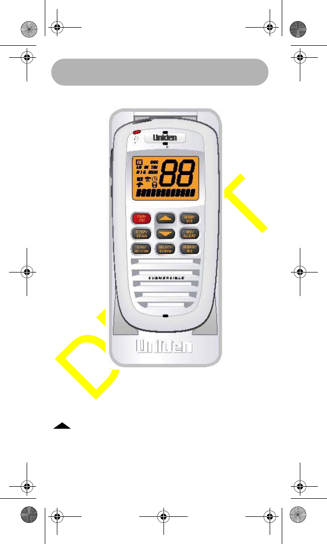
A Look at the Microphone
POWER/VOLUME - Hold down for 2 seconds to
turn the microphone on or off. Briefly press to select
the volume setting mode.
- Press to scroll up through the channels and
menu options. Hold down to increase scrolling
speed.
WHAMx4 Paper OMNEW.fm Page 10 Thursday, January 27, 2005 2:34 PM

Setting Up the Microphone 11
- Press to scroll down through the channels
and menu options. Hold down to increase scrolling
speed.
MENU HI/LO - Press to enter and exit the menu
mode. Hold down to change transmit power from
high to low. Hold down again to change transmit
power to high.
SELECT/SCRAM - Press in normal channel mode to
display the time, date, latitude, longitude, SOG
(speed over ground), and COG (course over ground).
Press in menu mode to select menu items. Hold
down to turn on the Scrambler for the current
channel.
16/9/TRIPLE WATCH - Press to tune to Channel 9
and Channel 16 and to use Triple Watch.
HAIL/INTERCOM - Press to turn the hailer on or off.
Hold down for 2 seconds to use the radio’s intercom
feature.
SQUELCH - Press to turn on the squelch setting
mode.
STEP/SCAN - Hold down to scan through all
channels in memory.
MEM/UIC - Press to place the currently selected
channel in memory. Press again to delete a channel
from memory. Hold down to change UIC mode.
WX/ALERT - Press to listen to the active weather
channel in your area. Hold down in weather alert
mode to turn on weather alert.
PTT - Press to transmit.
WHAMx4 Paper OMNEW.fm Page 11 Thursday, January 27, 2005 2:34 PM
Setting Up the Microphone
12
DISTRESS - Hold down for 5 seconds to turn on
distress transmit. The microphone counts down dur-
ing distress. If you release the key before the count-
down is finished, distress is automatically cancelled.
LIGHT/LOCK - Press to turn on the display and key-
pad backlight at its lowest level. Press again to
change the backlight to medium level. Press again
to change the backlight to high level. Press again to
turn off the backlight.
Hold down for 2 seconds to turn on keylock. All keys
are locked except PTT. To unlock the keypad, hold
down LIGHT/LOCK for 2 seconds or turn off the
microphone then turn it on again.
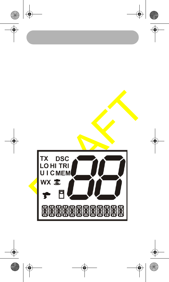
A Look at the Display
Status Icons
TX - Appears while the microphone is transmitting.
WHAMx4 Paper OMNEW.fm Page 12 Thursday, January 27, 2005 2:34 PM

Setting Up the Microphone 13
LO - Shows the transmit output power is set to 1
watt on the output channel.
HI - Shows the transmit output power is set to 25
watts on the output channel.
MEM - Indicates if a channel has been placed into
channel scanning memory.
TRI- Appears when the microphone is on a working
channel and is watching channel 16 and channel 9.
Also, additionally if watching the weather channel.
WX - Appears when the microphone is in the
weather mode.
- Appears when the weather alert channel
watch is active and blinks when the alert is acti-
vated.
U I C - Shows the channel mode (USA, INT, or
CAN).
DSC - Appears when the microphone is in the DSC
mode, including receiving DSC calls. It also shows
that the microphone is connected to the main radio
(by RF). It blinks when the microphone is close to
out of range, or when completely out of range.
GPS is connected to the microphone. The
signal wave portions of this icon will blink sequen-
tially to indicate that the GPS data being received is
valid.
This icon shows that the microphone is
connected to the main radio (by RF). It blinks when
the WHAMx4 is close to out of range, or when
completely out of range.
WHAMx4 Paper OMNEW.fm Page 13 Thursday, January 27, 2005 2:34 PM

Operation
14
Operation
Turning the Microphone On and Off
Hold down POWER/VOLUMEto turn on the
microphone. If the main radio is turned on, the
channel displayed will be the current channel
selected on the main Radio.
Hold down POWER/VOLUME again to turn off the
microphone.
Adjusting the Volume
Briefly press POWER/VOLUMEto adjust the
volume, then repeatedly press to turn the
volume up or to turn the volume down. Briefly
press POWER/VOLUME again to turn off volume
mode.
The microphone remember the last setting selected
before you turn it off.
Adjusting the Squelch/
Checking the Battery Level
Pressing this key will activate the Squelch setting
mode. When the Squelch setting mode is active,
pressing the UP or DOWN keys will adjust the set-
ting. Pressing the Squelch key again will deactivate
the Squelch setting mode. Also, the user can press
any key (except the UP and DOWN arrow keys) to
deactivate the Squelch setting mode. The Squelch
control will have 10 settings 0-9. The WHAMx4 will
remember the last setting selected before being
turned off.The default setting will be set to 4. The
following screen shows the Squelch setting mode.
Operation
WHAMx4 Paper OMNEW.fm Page 14 Thursday, January 27, 2005 2:34 PM

Operation 15
Pressing and holding the Squelch key will activate
the battery level display screen. The battery level
range will be 0~9 (0 being empty and 9 being full).
Any other key will deactivate this screen.
Using Triple Watch
When pressed, this key will immediately tune to
channel 16. This will occur no matter what channel
the radio is currently tuned to. When the key is
pressed a second time from the channel 16 display
mode, the WHAMx4 and the radio will instantly tune
to channel 9. A third press of the 16/9 key will then
go back to the original working channel that the user
started from.
The TRIPLE WATCH function will be activated if a
user is on a channel other than 16 or 9 and presses
and holds the 16/9 key for 2 seconds. The TRI icon
will then be displayed and the radio will check chan-
nel 16 every 2 seconds and then channel 9 immedi-
ately afterward, then return to the original working
channel.
NOTE: If the channel other than 16 and 9 is a
weather channel, the radio will automatically enter
the TRIPLE WATCH mode and will operate the
same as the MHS350.
*NOTE: If the weather alert is activated, the radio
will also work the same as the MHS350 by going
from the channel other than 16 or 9 (working chan-
nel) to 9 then 16 then back to the working channel.
Every 7 seconds the radio will also check the active
weather channel for the weather alert tone.
NOTE: If FIPS codes are assigned and the weather
alert is activated, the SAME weather function will
WHAMx4 Paper OMNEW.fm Page 15 Thursday, January 27, 2005 2:34 PM

Operation 16
not work in the TRIPLE WATCH mode. The radio
will only search for the 1050Hz tone.
Using WX/Alert
Pressing the WX/Alert key will allow the user to lis-
ten to the active NOAA weather channel in the local
area. Upon pressing the key, the weather channel
number that is active will be displayed in the chan-
nel display. The WX icon for weather will also be
displayed.
*NOTE: The weather channels can be changed by
pressing the UP arrow Key (increasing) or pressing
the DOWN arrow key (decreasing). The radio will
always return to the last weather channel selected.
This will even apply if the radio is turned off and then
turned back on again.
Pressing and holding the WX/Alert key for 2 sec-
onds will place the radio into the weather alert
mode. A flashing WX icon will indicate that the radio
is in weather alert mode. If FIPS codes are pro-
grammed, the icon will still flash and the nature of
the alert will be displayed in the text area of the dis-
play.
Using STEP/SCAN
The user will press this key to activate the step
operation. Every time this key is pressed, the radio
will step to the next channel that has been placed
into Memory (see MEM section). Pressing and hold-
ing this key for ~2 seconds will activate the channel
scan feature and the 2 segment channel numbers
will show the channels that are being scanned,
starting with the lowest channel number to the high-
WHAMx4 Paper OMNEW.fm Page 16 Thursday, January 27, 2005 2:34 PM

Operation 17
est. Any time that the scan is activated, the TRIPLE
WATCH function will also be activated and the TRI
icon will be displayed. During the scan mode the
radio will automatically check channels 16 and 9
every two seconds in the scan operation.
NOTE: The user will be able to press and hold the
16/9 key to take the radio out of TRIPLE watch but
still continue to SCAN.
Using MEM/UIC
Pressing this key briefly will place the displayed
channel into memory. Once a channel has been
programmed into memory, the MEM icon will be dis-
played each time the channel is shown in the LCD
screen. All channels will have the ability to be
stored in memory for scanning (except Weather
channels). Pressing this key briefly again will
remove the channel from memory.
Pressing and holding this key for ~2 seconds will
change the radio mode from USA to INTERNA-
TIONAL, to CANADIAN channel modes.
NOTE: The radio needs to remember which channel
was last selected in each of U,I,C so that when the
radio is switched modes the next time these modes
are selected the last channel is displayed. Also, this
will apply even if the radio is turned off. The initial
default channel for each mode is channel 16.
NOTE: To delete a channel from the memory, the
user will tune to the channel that they wish to delete
and press the MEM key. At that time the MEM icon
will be deactivated.
WHAMx4 Paper OMNEW.fm Page 17 Thursday, January 27, 2005 2:34 PM

Operation 18
Using Select/SCRAM
Pressing this key briefly while in the Menu mode will
select the menu items. Pressing and holding this
key will activate the Scramble mode for the selected
channel. Briefly pressing this key during the normal
channel operation mode, will activate the following
scrolling information : Current Local Time, Current
Position (Latitude/Longitude), SOG (Current Speed
Over Ground, and COG (Current Course Over
Ground). Pressing this key briefly again will deacti-
vate the scrolling information and return the display
to show the current channel name.
*NOTE: The channel mode display information will
be the priority and will be displayed whenever the
radio receives an incoming transmission or when
the radio is transmitting. The user can also toggle
back and forth between the two displays by pressing
the SELECT key from the channel display screen.
Using HAIL/INTERCOM
Pressing this key briefly will activate the Hailer fea-
ture. To adjust the outgoing volume, press the UP
arrow key to increase and the DOWN arrow key to
decrease. To adjust the incoming Hail volume,
briefly press the Volume key, then the UP arrow key
to increase and the DOWN arrow to decrease. The
following screen shows the Hailer mode. Press the
Hail key again briefly to exit the Hail mode.
Press the select key or the PTT key to choose the
Hailer mode.
Press and hold the Hail key for ~2 seconds to acti-
vate the Intercom feature. The user can now choose
WHAMx4 Paper OMNEW.fm Page 18 Thursday, January 27, 2005 2:34 PM

Operation 19
the units that they want to talk to: base radio 1, base
radio 2, WHAM 2, WHAM 3, WHAM 4, All, Group 1,
or Group 2. For which WHAM’s will be on the list will
depend on which WHAM number the user is using (
for the above example, the user is using WHAM 1).
There are 2 user programmable Groups for the
intercom. The following shows the Intercom select
screen.
Pressing the Select key or the PTT key will choose
the Intercom mode.
NOTE: The user has to set-up the Group 1 and
Group 2 in the Setup menu.
NOTE: Base Radio 2 will only be active in the menu
after the WHAMx4 is registered to recognize this
radio for Intercom purposes only.
NOTE: To use the PA feature, the user would just
install a non-listen-back type of speaker horn.
Using LIGHT/LOC
Press this key briefly to activate the Low backlight
setting. Press this key for a second time to select
the Medium backlight setting. Press this key a third
time to select the High backlight setting. Press this
key a fourth time to select the backlight Off setting.
Press and hold this key for ~2 seconds to activate
the Keylock feature. The only active key while in the
keylock mode is the PTT key. Either by pressing the
Light/Lock key for ~2 seconds, while in the Keylock
mode, or by turning off then on the WHAMx4 will
disable the Keylock feature.
WHAMx4 Paper OMNEW.fm Page 19 Thursday, January 27, 2005 2:34 PM

Operation 20
Using Distress
This key will be used to send a distress signal.
Please refer to the documents previously noted in
Section 4 (Documents Required To Build a DSC
radio) for more details on this feature.
Using MENU/H/L
Pressing this key briefly will activate the menu. The
menu will control the following categories: DSC
CALL, SETUP, SYSTEM. Within each of these cat-
egories, there will be submenu options that are out-
lined in the flowchart below. Pressing this key for ~2
seconds will change the transmit output power for
the currently selected channel from HI to LO or from
LO to HI depending on the current setting. Changing
to HI power is dependent on the particular FCC/IC
channel power restriction.
Using DSC Call
This section will detail the operation of the DSC
functions.
Using Individual Call
This option will allow the user to select a name from
their directory and make a call to that one individual.
Press the SELECT key and the first name alphabet-
ically will be displayed on the LCD. By pressing the
DOWN arrow key, the user will be able to scroll
through the names list until the EXIT option is dis-
played. At this point the user can press the SELECT
key to exit the MENU mode. If the user presses the
DOWN arrow key again while in this menu, the first
name will be displayed again (wrap around feature).
When the Individual menu is first entered, pressing
WHAMx4 Paper OMNEW.fm Page 20 Thursday, January 27, 2005 2:34 PM

Operation 21
the UP arrow key will move to the bottom of the
names list (wrap around feature). At any time while
in this menu, pressing the MENU key will move the
display back up to the DSC CALL menu.
By using the UP and DOWN arrow buttons, choose
a desired name, then press the SELECT key to
send the name of the person that is highlighted and
the WHAMX4 will continually scroll from right to left.
This information as well as a loud ringing tone will
come from the callers radio until the person who is
being called presses their PTT key to reply (or the
call times out after 5 minutes) which will disarm the
ringing tone from the radio.
NOTE: The Individual call information is setup using
the DIRECTORY menu.
NOTE: When the call is first made both the
WHAMx4, the main radio, and the called radio will
display channel 70 while the signal is received.
After all of the data is received, the receiving radio
will change channels to the channel that the trans-
mitting radio first sent the transmission out on.
Example: Radio one makes an individual call on
channel 17 and radio two is on channel 20. The
receiving radio will automatically change to channel
17 once the signal is received. The receiving radio
will also display the name of the party that has
called and the indicator of INDIVIDUAL.
Using Group
This function will be used to send a message to the
group of MMSI numbers.
WHAMx4 Paper OMNEW.fm Page 21 Thursday, January 27, 2005 2:34 PM

Operation 22
Starting from the Channel display mode, the user
will press the Menu key and the following screen will
appear.
Press the SELECT key and use the DOWN / UP
keys to display the following screen.
Press the SELECT key to send the GROUP call. Or
scroll down to Exit, then press SELECT to exit back
to the radio mode. By pressing the MENU key while
in this menu will return the radio to the DSC CALL
menu. When the GROUP CALL has been sent, the
following screen will be displayed until either a radio
in the group presses their PTT button or the call
times out after 5 minutes.
Using ALL SHIPS
This function will be used to send a message to all
ships. There will be three types of transmissions
that may be sent, URGENCY, SAFETY, ROUTINE.
Starting from the Channel display mode, the user
will press the Menu key.
Press the SELECT key and the DOWN or UP arrow
keys until the ALL Ships menu option is displayed .
The user will then use the DOWN or UP keys to
select the option call type that they wish to send.
Once the desired option is highlighted, the user will
press the SELECT key to send the call. Upon send-
ing the call the WHAMx4 will display the channel
mode screen with channel 70 showing. The radio
will go to the specified channel above based upon
the type of call that is being made. (Either 16 or the
channel that the transmission was made from).
WHAMx4 Paper OMNEW.fm Page 22 Thursday, January 27, 2005 2:34 PM

Operation 23
NOTE: When sending either an URGENCY or
SAFETY message, both radios will automatically
move to channel 70 until all of the data is received
and then both radios will go to channel 16 for trans-
missions and replies. The URGENCY transmission
will need to send a siren type audio tone while the
SAFETY and ROUTINE options may just send a
regular calling tone. The ROUTINE transmission
will go to channel 70 until all data is transmitted,
then the WHAMx4, the main radio, and the called
radios will go to the channel that the transmission
originated from.
NOTE: The receiving radio will display ALL SHIPS
and the name of the sender as illustrated below.
This display will occur for any type of ALL SHIPS
call.
Using Geographical Call
This option will only be available in the DSC call
section of the menu if there is an external GPS mod-
ule attached to the NMEA0183 jack. This operation
will work exactly the same as an INDIVIDUAL call
except that the receiving radio will display the fol-
lowing screen.
Position Request
This function will be used to request the position of
another DSC radio.
Starting from the Channel display mode, the user
will press the Menu key and the following screen will
appear.
Using the Down and Up key to scroll to the desired
name, then press the Select key to transmit the
WHAMx4 Paper OMNEW.fm Page 23 Thursday, January 27, 2005 2:34 PM

Operation 24
Position Request command. The following screen
will be displayed while the WHAMx4 is waiting for
the called radio to answer.
When the called radio answers, and contains posi-
tion information, the information appears on the
microphone’s display.
Position Send
The feature will allow the WHAMx4 to send the cur-
rent radio position (Lat/Long/Time/Date) if both, the
radio is connected to a GPS and is receiving valid
position information. The following explains the
operation of this feature starting with the normal
channel screen.
When the WHAMx4 receives a position send
request from another radio, the WHAMx4 will either,
automatically send the position/time/date informa-
tion, display the confirmation, and alert the user by
ringing the radio (press any key to disable the ring-
ing).
Using Standby
The WHAMx4 will allow the user to place the radio
in an unattended mode. This will not allow an
incoming DSC call. The user will need to place the
radio in this mode if they will be away from the radio
and not wish to answer any calls. The following
screens illustrate how this function is activated.
Starting from the Channel display mode, the user
will press the Menu key and the following screen will
appear.
Press the Down or Up arrow keys to display the
Standby feature.
WHAMx4 Paper OMNEW.fm Page 24 Thursday, January 27, 2005 2:34 PM

Operation 25
NOTE: The user can press any key on the
WHAMx4 or the PTT key to deactivate this feature.
When this mode is activated the WHAMx4 will
receive quick beep tones indicating that a call is
coming in. The WHAMx4 will automatically reply to
the call on channel 70 and then return to the work-
ing channel with the screen shown directly above.
Using Call Waiting
This feature allows the user to view a list of received
calls that came into the WHAMX4 while either in
STANDBY mode or if a call timed out after 5 minutes
and went into the Call Wait log.
Starting from the Channel display mode, the user
will press the Menu key and the following screen will
appear.
Press the Down or Up arrow keys to display the
CALL WAIT option. The following screen will be dis-
played.
Press the Select key and the following screen will
give the user three options to view the logged mes-
sages, DISTRESS, INDIVIDUAL, or the EXIT
option. By using the DOWN and UP arrow keys, the
WHAMx4 will display the desired choice.
From this screen, the user can press the SELECT
key and use the DOWN and UP arrow keys to scroll
through the logged calls.
The user can then press the SELECT key to get fur-
ther information about the call that came in.
NOTE: If the call that is being viewed in the log
came in without GPS information, the user will press
in on the SELECT key.
WHAMx4 Paper OMNEW.fm Page 25 Thursday, January 27, 2005 2:34 PM

Operation 26
The user can either choose to select SEND by
pressing the SELECT key or can use the DOWN or
UP arrow to display the EXIT option.
Choosing the Send option will act as just like an
INDIVIDUAL call.
Choosing the EXIT option will take the user back
one level to the list of names. The user can use the
DOWN or UP arrow keys scroll to the bottom of the
list of names and choose the EXIT option and con-
tinue to back out of the menu options one level at a
time.
NOTE: In the CALL WAIT log, the DISTRESS cate-
gory must be able to store the last 20 calls that
came in purging and deleting the oldest of the 20 to
receive the new incoming. The INDIVIDUAL cate-
gory must be able to store the last 50 incoming calls
that came in purging and deleting the oldest of the
50 to receive the new incoming.
This screen will display the callers’ date and time
that the call was received. The user will be able to
send a DSC call back to the waiting message be
pressing the SELECT key, or the user may select
EXIT by using the DOWN or UP arrow keys and
back up one level in the CALL WAIT menu.
NOTE: If a call comes in and is not received, a call
in absence indicator will be displayed. If the receiv-
ing radio is in STANDBY mode, the screen will show
the following (the entire scrolling text will be blink-
ing).
Using Fog Horn
This feature allows the user to generate fog horn
sounds from the optional hailer horn/horns attached
WHAMx4 Paper OMNEW.fm Page 26 Thursday, January 27, 2005 2:34 PM

Operation 27
to the main radio. There are fixed sounds depending
on the following conditions.
AUTOMATIC – (Automatic) Fog horn from the fol-
lowing list depending on GPS (stopped, moving,
powerboat, etc…)
MANUAL - (Manual) Use of the horn signal for
passing.
UNDERWAY – (Automatic) Fog signal for Power
Boat underway.
STOP – (Automatic) Fog signal for vessel that is
stationary (stopped).
SAIL – (Automatic) Fog signal for sailboat, fishboat,
towboat.
TOW – (Automatic) Fog signal for vessels under
tow.
ANCHOR – (Automatic) Fog signals for any vessel
at anchor.
AGROUND – (Automatic) Fog signals for any ves-
sel aground.
YELP – (Manual) Yelp type siren for Police, Fish &
Game, US Coast Guard.
From the Menu, use the UP and DOWN arrow keys
to highlight the fog horn feature and press the
Select key.
For all selections, except automatic, after selecting
an option the WHAMx4 will return to the main menu.
For the Automatic setting, the following screen will
be displayed.
WHAMx4 Paper OMNEW.fm Page 27 Thursday, January 27, 2005 2:34 PM

Operation 28
Setting Up the Microphone
This portion of the menu system deals with features
that the user may wish to change, however, these
features are mostly adjusted on the initial setup of
the radio or WHAMx4. Most of these features are
not changed as commonly as the items in the sys-
tem section of the menu.
The user will press the MENU key and use the
DOWN or UP arrow keys to display the SETUP
option. By pressing the SELECT key, the WHAMx4
will enter the SETUP mode. By pressing the DOWN
or UP arrow keys and then the SELECT key, the fol-
lowing System options are entered.
Using the Directory
This feature in the setup menu will allow the user to
set up a directory of other boaters with DSC capable
radios that have an MMSI. The following screens
will allow the user to setup and alphanumeric iden-
tity as well as the corresponding MMSI number.
The following screens and commands will illustrate
the operation of this feature.
Press the SELECT key.
Use the UP and DOWN arrows to move through the
alphabet until the desired letter/number is reached
(example “A”). At that time the user will press the
SELECT key and the next space will start flashing.
The same process will be repeated until the alpha
tag is complete. Once completed, the second
space after MMSI will start flashing and the same
process will be used to program in the MMSI num-
ber.
WHAMx4 Paper OMNEW.fm Page 28 Thursday, January 27, 2005 2:34 PM

Operation 29
Pressing the SELECT key will return to the Directory
menu. If there are already entries in the directory,
pressing the UP and DOWN arrow keys will scroll
through the names alphabetically. Also, the UP and
DOWN arrow keys will wrap around once the end of
the directory has been reached.
Located at the last positions of the Directory are
NEW, MODIFY, DELETE, and EXIT.
*NOTE: Please see the following as a list of the
alpha characters that will be available for program-
ming:
ABCDEFGHIJKLMNOPQRSTUVWXYZabcdefghij
klmnopqrstuvwxyz1234567890.,/’:+-& and
(BLANK).
1.15.2Channel Tag (Name)
This item in the Setup menu will allow the user to
change the normal channel tags (names). This is
necessary when the user needs to change the
channel tag depending what the channel’s autho-
rized use is for that area. From the SETUP Menu,
press the DOWN or UP arrow keys until the follow-
ing screen is displayed.
NOTE: The user will need to place the WHAMx4
onto the desired channel before they can change
the channel tag for that channel.
Pressing the UP or DOWN arrow keys will scroll
through a list of preprogrammed channel names.
Pressing the SELECT key will select one of these
names. OR, from the Channel Name screen, press-
ing select twice will highlight the first character of the
channel name and using the UP and DOWN arrow
WHAMx4 Paper OMNEW.fm Page 29 Thursday, January 27, 2005 2:34 PM

Operation 30
keys will select a new first character. After choosing
the first character, pressing the SELECT key will
flash the second character. Repeating this process
for a maximum of a 12 character channel name.
Pressing the SELECT key again will return the radio
to the Setup mode.
Adjusting the Local Time
This feature will allow the user to fine tune the Local
Time for any location in North America. This feature
allows adjustment to the Local Time by +/- 1 hour.
From the SETUP Menu, press the DOWN or UP
arrow keys.
Pressing the Select key will now allow the user to
adjust the local time.
Turning Daylight Saving On or Off
This feature allows the user to select the automatic
daylight savings for the Clock feature. From the
SETUP Menu, press the DOWN or UP arrow keys
until the following screen is displayed.
Pressing the SELECT key will accept this setting
and return the radio to the System menu.
Programming a FIPS Code
This option from the menu system will allow the user
the ability to add FIPS codes in order to activate the
Specific Area Message Encoding (S.A.M.E.)
weather alert system. The following screens will be
used to program FIPS codes and to activate the
weather alert.
Press the SELECT key and use the DOWN or UP
keys desired location of the FIPS code that the user
WHAMx4 Paper OMNEW.fm Page 30 Thursday, January 27, 2005 2:34 PM

Operation 31
wants to enter then press the SELECT key. If a
FIPS code has not yet been entered to the location,
the number 0 will be flashing in the first location. If a
FIPS code has already been programmed into the
location, the first digit of that code will be blinking.
To increase the number, press the UP arrow key.
Press the DOWN arrow key to decrease. Below are
the screens and commands to program a FIPS
code.
Press the SELECT key. The first zero will be blink-
ing and the user will Press the UP arrow key to
show a 5. The user will then press the SELECT key
to move to the next blinking zero.
This process will be repeated for all 6 digits of the
FIPS code. When the final digit is programmed,
pressing the DOWN or UP arrow key will move to
the next location. This process can be used to input
up to all 30 FIPS codes. To exit the FIPS code pro-
gramming screen, the user will press the MENU
key. Upon pressing the Menu key, the user will
come back to the following screen.
Note : There will be a minimum of 20 FIPS memory
locations.
Using Auto Channel Switch
This item in the Setup menu will allow the user turn
on or off the automatic channel change during a
DSC call. This is necessary when the user is using
the radio, and because of safety reasons, does not
want the radio to switch channels.
Pressing the SELECT key will accept this setting
and return the radio to the Setup menu.
WHAMx4 Paper OMNEW.fm Page 31 Thursday, January 27, 2005 2:34 PM

Operation 32
Using Position Reply
This item in the Setup menu will allow the user turn
on or off the automatic Position Reply when another
DSC radio asks for the users position. This is neces-
sary when the user does not want other radios know
his position. From the SETUP Menu, press the
DOWN or UP arrow keys until the following screen
is displayed.
Using a Group MMSI
This feature allows the user to setup an MMSI num-
ber so that they can make a single call to a group of
boats. Below are the operational screens for pro-
gramming the group MMSI number.
Press the SELECT key to show the MMSI program-
ming screen.
The first zero will be flashing. The user will use the
UP or DOWN arrow keys to increase or decrease
the zero to a number such as 6. Pressing the UP
arrow key will increase the number; pressing the
DOWN arrow key will make the number decrease.
Once the correct number is displayed, the user will
press the SELECT key to confirm and the next zero
will blink. This process will be repeated until all 9
digits are confirmed. (See Below)
After the final digit is selected, pressing the SELECT
key will confirm the MMSI entry and the Display will
show the following screen. If the user presses the
MENU key while in the MMSI entry screen, the radio
will exit the MENU mode without retaining the MMSI
number.
WHAMx4 Paper OMNEW.fm Page 32 Thursday, January 27, 2005 2:34 PM

Operation 33
The user can now use the DOWN and UP arrow
keys to display and SELECT to exit the Menu.
Using the Scrambler
This option requires the user to install the optional
Scramble PC board into the main radio. If the
optional PC board is not installed, the WHAMx4 will
display the following message indicating that this
feature is not available.
Pressing the select key will activate the next screen.
After the 3 digit scramble code has been entered,
the WHAMx4 will return to the Setup menu screen.
Exiting a Menu
This option will allow the user to quickly exit the
menu options screen and return back to the channel
display screen. This option is found in the DCS
CALL, SYSTEM, and SETUP sections of the menu
system. A user will move to the EXIT option (using
the DOWN and UP arrow keys) and pressing the
SELECT key in order to exit the menu system and
return to the channel display mode.
Setting Up the System
This portion of the menu system deals with options
that the user may wish to adjust based upon condi-
tions or preferences. The user will press the MENU
key and use the DOWN or UP arrow keys to display
the SYSTEM option. By pressing the SELECT key,
the radio will enter the SYSTEM mode.
Adjusting the Contrast
This option will allow the user to change the contrast
levels of the WHAMx4 LCD. Setting this feature
WHAMx4 Paper OMNEW.fm Page 33 Thursday, January 27, 2005 2:34 PM

Operation 34
when, using the WHAMX4 DOES NOT affect the
contrast setting on the main radio or other WHAMX4
units that may be operational on the system. This
feature will use the DOWN and UP arrow keys to
change the contrast level on the LCD screen. The
contrast will change on the LCD will be shown in the
channel area of the display. Pressing the UP arrow
key will increase the contrast. Pressing the DOWN
arrow key will decrease the amount of contrast.
Once the contrast level appears to the users’ satis-
faction, the SELECT key will be pressed and the
radio will return to the channel display screen. Upon
returning to the channel display screen all informa-
tion will be the same as it was before the user
entered the menu system.
NOTE: This function needs to have a reset in case
the LCD screen becomes unreadable due to envi-
ronmental changes. The default setting should be
level four of seven on the LCD. To reset all of the
features to the factory settings the user will hold in
the Menu key while turning the radio on. THIS
WILL NOT RESET THE MMSI.
Adjusting the Key Beep
This feature will allow the user to turn on or off the
key beep tones. From the SETUP Menu, press the
DOWN or UP arrow keys until the following screen
is displayed.
Pressing the SELECT key will accept this setting
and return the radio to the System menu.
WHAMx4 Paper OMNEW.fm Page 34 Thursday, January 27, 2005 2:34 PM

Operation 35
DSC Alarm Level
This menu option enable the user to select the type
of alarm that will be used when receiving a DSC
alert or call. The idea is that normally the alert or
ring is a fixed level. This option will allow the user to
choose a fixed type of alarm or a slowly increasing
alarm. The slowly increasing alarm would allow the
user to “any key” shut off the alarm before the alarm
level gets loud.
Pressing the Select key will activate the next
screen.
By using the UP or DOWN arrows, the user can dis-
play the alarm choice and then press the Select key.
If the Menu key is pressed, then no change in alarm
type will be entered. Pressing the Select key will
save the alarm choice and return to the System
menu.
Adjusting the WX Alarm Level
This menu option will enable the user to select the
type of alarm sound they will hear when there is an
Emergency/Weather alert. From the System menu,
Select the WX Alarm Level option.
By pressing the Select key, the following options are
available.
By using the UP or DOWN arrows, the user can dis-
play the alarm choice and then press the Select key.
If the Menu key is pressed, then no change in alarm
type will be entered. Pressing the Select key will
save the alarm choice and return to the System
menu.
WHAMx4 Paper OMNEW.fm Page 35 Thursday, January 27, 2005 2:34 PM

Operation 36
Using Self Test
This menu item will activate, through the WHAMx4,
a self test of the main radio. The main radio con-
stantly monitors these items, but there are time
when a user may want to run a diagnostic on the
main radio. This test will include the current
WHAMx4 link signal condition, by reading the RSSI
level. The self test will include the following items.
These items will be displayed one-by-one until all
items have been displayed. Any items that have
problems detected will continue to scroll after the
test is complete. To cancel showing the failed items,
either press the menu or select keys to return to the
System menu.
Antenna Condition (OK, Open, Shorted)
GPS Condition (OK, No Data Flow, Not Connected)
WHAM (OK, Poor Signal)
Battery (OK, Too Low, Too High)
Adjusting the VOX Sensitivity Level
This menu option will allow the user to adjust the
VOX sensitivity level for the environment they are
using the optional headset.
From the System menu, use the UP and DOWN
arrow keys to activate the next screen.
Press the Select key to activate the next screen.
Press the UP and Down arrow keys to choose the
VOX sensitivity level (Of, 1, 2, 3) and press the
Select key to save or the Menu key to exit. Either
way the System menu is Selected.
WHAMx4 Paper OMNEW.fm Page 36 Thursday, January 27, 2005 2:34 PM

Operation 37
Using Handset Paging
The menu item is used to find a misplaced WHAMx4
Handset. This feature will allow the user to find any-
one of, or all handsets (upto 3 from any WHAMx4).
From the Main Menu, use the UP or Down arrow
keys to display the next screen.
Press the Select key to activate the next screen.
By using the UP and DOWN arrow key, the user can
choose which handset or all handsets (2, 3, 4, AL)
(assuming for this example that we are using hand-
set number 1 to find a missing handset). Pressing
the Select key will activate the handset page and
the missing handset should start beeping (the hand-
set should beep for 1 minute unless any key is
pressed on that handset. If either the Select key or
the Menu key is pressed, the Main menu screen is
selected.
WHAMx4 Paper OMNEW.fm Page 37 Thursday, January 27, 2005 2:34 PM

Care and Maintenance 38
Care and Maintenance
Your WHAMx4 Wireless Microphone is a precision
electronic instrument and you should treat it
accordingly. Due to its rugged design, very little
maintenance is required. However, a few precau-
tions should be observed.
• If the antenna has been damaged, you should
not transmit except in the case of an emergency.
A defective antenna may cause damage to your
microphone.
• You are responsible for continued FCC technical
compliance of your microphone.
• You are urged to arrange for periodic
performance checks with your Uniden Marine
dealer.
Care and Maintenance
WHAMx4 Paper OMNEW.fm Page 38 Thursday, January 27, 2005 2:34 PM

Specifications 39
Specifications
NEED THESE
Specifications
WHAMx4 Paper OMNEW.fm Page 39 Thursday, January 27, 2005 2:34 PM

Appendix 40
Appendix
Reference Information
USA/Canadian/International
Channel Frequencies
Ch.
No.
US CAN INT RX TX Status Full Name 12-Character Name
1”A” X 156.0500 156.0500 Simplex VESSEL TRAFFIC
SYSTEM/COMMERCIAL
VTS/COMMERCL
3”A” X 156.1500 156.1500 Simplex COAST GUARD, GOVT
ONLY
CG ONLY
5”A” X 156.2500 156.2500 Simplex VESSEL TRAFFIC
SYSTEM/COMMERCIAL
VTS/COMMERCL
6X 156.3000 156.3000 Simplex INTER-SHIP SAFETY SAFETY
7”A” X 156.3500 156.3500 Simplex COMMERCIAL COMMERCIAL
8X 156.4000 156.4000 Simplex COMMERCIAL COMMERCIAL
9X 156.4500 156.4500 Simplex NON COMMERCIAL NON COMMERCL
10 X 156.5000 156.5000 Simplex COMMERCIAL COMMERCIAL
11 X 156.5500 156.5500 Simplex VESSEL TRAFFIC
SYSTEM
VSL TRAFFIC
12 X 156.6000 156.6000 Simplex VESSEL TRAFFIC
SYSTEM
VSL TRAFFIC
13 X 156.6500 156.6500 Simplex,
1W
BRIDGE TO BRIDGE BRDG TO BRDG
14 X 156.7000 156.7000 Simplex VESSEL TRAFFIC
SYSTEM
VSL TRAFFIC
15 X 156.7500 Inhibit Receive
Only
ENVIRONMENTAL ENVIRONMENTL
16 X 156.8000 156.8000 Simplex DISTRESS, SAFETY,
CALLING
DITRESS
17 X 156.8500 156.8500 Simplex,
1W
GOVT MARITIME
CONTROL
GOVERNMENT
18”A” X 156.9000 156.9000 Simplex COMMERCIAL COMMERCIAL
19”A” X 156.9500 156.9500 Simplex COMMERCIAL COMMERCIAL
20”A” X 157.0000 157.0000 Simplex PORT OPERATION PORT OPERATN
21”A” X 157.0500 157.0500 Simplex COAST GUARD ONLY COAST GUARD
22”A” X 157.1000 157.1000 Simplex COAST GUARD COAST GUARD
23”A” X 157.1500 157.1500 Simplex COAST GUARD ONLY COAST GUARD
24 X 161.8000 157.2000 Duplex MARINE OPERATOR MAR OPERATOR
25 X 161.8500 157.2500 Duplex MARINE OPERATOR MAR OPERATOR
26 X 161.9000 157.3000 Duplex MARINE OPERATOR MAR OPERATOR
27 X 161.9500 157.3500 Duplex MARINE OPERATOR MAR OPERATOR
28 X 162.0000 157.4000 Duplex MARINE OPERATOR MAR OPERATOR
61”A” X 156.0750 156.0750 Simplex COAST GUARD COAST GUARD
63”A” X 156.1750 156.1750 Simplex VESSEL TRAFFIC
SYSTEM
VSL TRAFFIC
64”A” X 156.2250 156.2250 Simplex COMMERCIAL COMMERCIAL
65”A” X 156.2750 156.2750 Simplex PORT OPERATION PORT OPERATN
66”A” X 156.3250 156.3250 Simplex PORT OPERATION PORT OPERATN
67 X 156.3750 156.3750 Simplex,
1W
BRIDGE TO BRIDGE BRDG TO BRDG
68 X 156.4250 156.4250 Simplex NON COMMERCIAL NON COMMERCL
69 X 156.4750 156.4750 Simplex NON COMMERCIAL NON COMMERCL
70 X 156.5250 Inhibit Receive
Only
DIGITAL SELECTIVE
CALLING
DSC REC ONLY
71 X 156.5750 156.5750 Simplex NON COMMERCIAL NON COMMERCL
72 X 156.6250 156.6250 Simplex NON COMMERCIAL
(SHIP-SHIP)
NON COMMERCL
73 X 156.6750 156.6750 Simplex PORT OPERATION PORT OPERATN
74” X 156.7250 156.7250 Simplex PORT OPERATION PORT OPERATN
75 X 156.775 156.775 Simplex,
1W
PORT OPERATION PORT OPERATN
76 X 156.825 156.825 Simplex,
1W
PORT OPERATION PORT OPERATN
77 X 156.8750 156.8750 Simplex,
1W
PORT OPERATION
(SHIP-SHIP)
PORT OPERATN
78”A” X 156.9250 156.9250 Simplex NON COMMERCIAL NON COMMERCL
79”A” X 156.9750 156.9750 Simplex COMMERCIAL COMMERCL
80”A” X 157.0250 157.0250 Simplex COMMERCIAL‘ COMMERCIAL
81”A” X 157.0750 157.0750 Simplex COAST GUARD COAST GUARD
82”A” X 157.1250 157.1250 Simplex COAST GUARD COAST GUARD
83”A” X 157.1750 157.1750 Simplex GOVERNMENT GOVERNMENT
84” X 161.8250 157.2250 Duplex MARINE OPERATOR MAR OPERATOR
85 X 161.8750 157.2570 Duplex MARINE OPERATOR MAR OPERATOR
86 X 161.9250 157.3250 Duplex MARINE OPERATOR MAR OPERATOR
87 X 161.9750 157.3750 Duplex MARINE OPERATOR MAR OPERATOR
88 X 162.0250 157.4250 Duplex MARINE OPERATOR MAR OPERATOR
Appendix
WHAMx4 Paper OMNEW.fm Page 40 Thursday, January 27, 2005 2:34 PM

Appendix 41
Ch.
No.
US
A
CAN INT RX TX Status Full Name 12-Character Name
88”A” X 157.4250 157.4250 Simplex COMMERCIAL (SHIP-
SHIP)
COMMERCIAL
1X
160.6500 156.0500 Duplex MARINE OPERATOR MAR OPERATOR
2X
160.7000 156.1000 Duplex MARINE OPERATOR MAR OPERATOR
3X
160.7500 156.1500 Duplex MARINE OPERATOR MAR OPERATOR
4”A” X 156.2000 156.2000 Simplex CANADIAN COAST
GUARD
COAST GUARD
5”A” X 156.2500 156.2500 Simplex VESSEL TRAFFIC
SYSTEM
VSL TRAFFIC
6X
156.3000 156.3000 Simplex INTER-SHIP SAFETY SAFETY
7”A” X 156.3500 156.3500 Simplex COMMERCIAL COMMERCIAL
8X
156.4000 156.4000 Simplex COMMERCIAL COMMERCIAL
9X
156.4500 156.4500 Simplex BOATER CALLING
CHANNEL
CALLING
10 X 156.5000 156.5000 Simplex COMMERCIAL COMMERCIAL
11 X 156.5500 156.5500 Simplex VESSEL TRAFFIC
SYSTEM
VSL TRAFFIC
12 X 156.6000 156.6000 Simplex VESSEL TRAFFIC
SYSTEM
VSL TRAFFIC
13 X 156.6500 156.6500 Simplex,
1W
BRIDGE TO BRIDGE BRDG TO BRDG
14 X 156.7000 156.7000 Simplex VESSEL TRAFFIC
SYSTEM
VSL TRAFFIC
15 X 156.7500 156.7500 Simplex ENVIRONMENTAL ENVIRONMENTL
16 X 156.8000 156.8000 Simplex DISTRESS, SAFETY,
CALLING
DITRESS
17 X 156.8500 156.8500 Simplex,
1W
STATE CONTROL STATE CNTRL
18”A” X 156.9000 156.9000 Simplex COMMERCIAL COMMERCIAL
19”A” X 156.9500 156.9500 Simplex CANADIAN COAST
GUARD
COAST GUARD
20 X 161.6000 157.0000 Duplex,
1W
PORT OPERATION PORT OPERATN
21”A” X 157.0500 157.0500 Simplex CANADIAN COAST
GUARD
COAST GUARD
22”A” X 157.1000 157.1000 Simplex CANADIAN COAST
GUARD
COAST GUARD
23 X 161.7500 157.1500 Duplex CANADIAN COAST
GUARD
COAST GUARD
24 X 161.8000 157.2000 Duplex MARINE OPERATOR MAR OPERATOR
25 X 161.8500 157.2500 Duplex MARINE OPERATOR MAR OPERATOR
26 X 161.9000 157.3000 Duplex MARINE OPERATOR MAR OPERATOR
27 X 161.9500 157.3500 Duplex MARINE OPERATOR MAR OPERATOR
28 X 162.0000 157.4000 Duplex MARINE OPERATOR MAR OPERATOR
60 X 160.6250 156.0250 Duplex MARINE OPERATOR MAR OPERATOR
61”A” X 156.0750 156.0750 Simplex CANADIAN COAST
GUARD
COAST GUARD
62”A” X 156.1250 156.1250 Simplex CANADIAN COAST
GUARD
COAST GUARD
64 X 160.8250 156.2250 Duplex MARINE OPERATOR MAR OPERATOR
64”A” X 156.2250 156.2250 Simplex MARINE OPERATOR MAR OPERATOR
65”A” X 156.2750 156.2750 Simplex SEARCH AND RESCUE SRCH RESCUE
66”A” X 156.3250 156.3250 Simplex,
1W
PORT OPERATION PORT OPERATN
67 X 156.3750 156.3750 Simplex BRIDGE TO BRIDGE BRDG TO BRDG
68 X 156.4250 156.4250 Simplex NON COMMERCIAL NON COMMERCL
69 X 156.4750 156.4750 Simplex NON COMMERCIAL NON COMMERCL
70 X 156.5250 Inhibit Receive
Only
DIGITAL SELECTIVE
CALLING
DSC REC ONLY
71” X 156.5750 156.5750 Simplex NON COMMERCIAL NON COMMERCL
72 X 156.6250 156.6250 Simplex NON COMMERCIAL NON COMMERCL
73 X 156.6750 156.6750 Simplex PORT OPERATION PORT OPERATN
74 X 156.7250 156.7250 Simplex PORT OPERATION PORT OPERATN
77 X 156.8750 156.8750 Simplex,
1W
PORT OPERATION PORT OPERATN
78”A” X 156.9250 156.9250 Simplex INTER SHIP INTER SHIP
79”A” X 156.9750 156.9750 Simplex INTER SHIP INTER SHIP
80”A” X 157.0250 157.0250 Simplex INTER SHIP INTER SHIP
81”A” X 157.0750 157.0750 Simplex CANADIAN COAST
GOARD
COAST GUARD
82”A” X 157.1250 157.1250 Simplex CANADIAN COAST
GUARD
COAST GUARD
83” X 161.7750 157.1750 Duplex CANADIAN COAST
GOARD
COAST GOARD
83”A” X 157.1750 157.1750 Simplex CANADIAN COAST
GOARD
COAST GOARD
84 X 161.8250 157.2250 Duplex MARINE OPERATOR MAR OPERATOR
85 X 161.8750 157.2750 Duplex MARINE OPERATOR MAR OPERATOR
86 X 161.9250 157.3250 Duplex MARINE OPERATOR MAR OPERATOR
87 X 161.9750 157.3750 Duplex MARINE OPERATOR MAR OPERATOR
88 X 162.0250 157.4250 Duplex MARINE OPERATOR MAR OPERATOR
WHAMx4 Paper OMNEW.fm Page 41 Thursday, January 27, 2005 2:34 PM

Appendix 42
Weather Channel Frequencies
Ch.
No.
US
A
CAN INT RX TX Status Full Name 12-Character Name
1X
160.6500 156.0500 Duplex MARINE OPERATOR MAR OPERATOR
2X
160.7000 156.1000 Duplex MARINE OPERATOR MAR OPERATOR
3X
160.7500 156.1500 Duplex MARINE OPERATOR MAR OPERATOR
4X
160.8000 156.2000 Duplex MARINE OPERATOR MAR OPERATOR
5X
160.8500 156.2500 Duplex MARINE OPERATOR MAR OPERATOR
6X
156.3000 156.3000 Simplex INTER-SHIP SAFETY SAFETY
7X
160.9500 156.3500 Duplex MARINE OPERATOR MAR OPERATOR
8X
156.4000 156.4000 Simplex COMMERCIAL (SHIP-
SHIP)
COMMERCIAL
9X
156.4500 156.4500 Simplex BOATER CALLING
CHANNEL
CALLING
10 X 156.5000 156.5000 Simplex COMMERCIAL COMMERCIAL
11 X 156.5500 156.5500 Simplex VESSEL TRAFFIC
SYSTEM
VSL TRAFFIC
12 X 156.6000 156.6000 Simplex VESSEL TRAFFIC
SYSTEM
VSL TRAFFIC
13 X 156.6500 156.6500 Simplex BRIDGE TO BRIDGE BRDG TO BRDG
14 X 156.7000 156.7000 Simplex VESSEL TRAFFIC
SYSTEM
VSL TRAFFIC
15 X 156.7500 156.7500 Simplex,
1W
ENVIRONMENTAL ENVIRONMENTL
16 X 156.8000 156.8000 Simplex DISTRESS, SAFETY,
CALLING
DITRESS
17 X 156.8500 156.8500 Simplex,
1W
GOVT MARINE CONTROL GOVERNMENT
18 X 161.5000 156.9000 Duplex PORT OPERATION PORT OPERATN
19 X 161.5500 156.9500 Duplex COMMERCIAL COMMERCIAL
20 X 161.6000 157.0000 Duplex PORT OPERATION PORT OPERATN
21 X 161.6500 157.0500 Duplex PORT OPERATION PORT OPERATN
22 X 161.7000 157.1000 Duplex PORT OPERATION PORT OPERATN
23 X 161.7500 157.1500 Duplex MARINE OPERATOR MAR OPERATOR
24 X 161.8000 157.2000 Duplex MARINE OPERATOR MAR OPERATOR
25 X 161.8500 157.2500 Duplex MARINE OPERATOR MAR OPERATOR
26 X 161.9000 157.3000 Duplex MARINE OPERATOR MAR OPERATOR
27 X 161.9500 157.3500 Duplex MARINE OPERATOR MAR OPERATOR
28 X 162.0000 157.4000 Duplex MARINE OPERATOR MAR OPERATOR
60 X 160.6250 156.0250 Duplex MARINE OPERATOR MAR OPERATOR
61 X 160.6750 156.0750 Duplex MARINE OPERATOR MAR OPERATOR
62 X 160.7250 156.1250 Duplex MARINE OPERATOR MAR OPERATOR
63 X 160.7750 156.1750 Duplex MARINE OPERATOR MAR OPERATOR
64 X 160.8250 156.2250 Duplex MARINE OPERATOR MAR OPERATOR
65 X 160.8750 156.2750 Duplex MARINE OPERATOR MAR OPERATOR
66 X 160.9250 156.3250 Duplex MARINE OPERATOR MAR OPERATOR
67 X 156.3750 156.3750 Simplex BRIDGE TO BRIDGE BRDG TO BRDG
68 X 156.4250 156.4250 Simplex NON COMMERCIAL NON COMMERCL
69 X 156.4750 156.4750 Simplex NON COMMERCIAL NON COMMERCL
70 X 156.5250 Inhibit Receive
Only
DIGITAL SELECTIVE
CALLING
DSC REC ONLY
71 X 156.5750 156.5750 Simplex NON COMMERCIAL NON COMMERCL
72 X 156.6250 156.6250 Simplex NON COMMERCIAL NON COMMERCL
73 X 156.6750 156.6750 Simplex PORT OPERATION PORT OPERATN
74 X 156.7250 156.7250 Simplex PORT OPERATION PORT OPERATN
77 X 156.8750 156.8750 Simplex PORT OPERATION
(SHIP-SHIP)
PORT OPERATN
78 X 161.5750 156.9250 Duplex PORT OPERATION PORT OPERATN
79 X 161.5750 156.9750 Duplex PORT OPERATION PORT OPERATN
80 X 161.6250 157.0250 Duplex PORT OPERATION PORT OPERATN
81 X 161.6750 157.0750 Duplex PORT OPERATION PORT OPERATN
82 X 161.7250 157.1250 Duplex PORT OPERATION PORT OPERATN
83 X 161.7750 157.1750 Duplex PORT OPERATION PORT OPERATN
84 X 161.8250 157.2250 Duplex MARINE OPERATOR MAR OPERATOR
85 X 161.8750 157.2750 Duplex MARINE OPERATOR MAR OPERATOR
86 X 161.9250 157.3250 Duplex MARINE OPERATOR MAR OPERATOR
87 X 161.9750 157.3750 Duplex MARINE OPERATOR MAR OPERATOR
88 X 162.0250 157.4250 Duplex MARINE OPERATOR MAR OPERATOR
Ch. No. RX Frequency Description (Receive Only)
WX01 162.5500 Weather Information (
WX02 162.4000 Weather Information (
WX03 162.4750 Weather Information (
WX04 162.4250 Weather Information (
WX05 162.4500 Weather Information (
WX06 162.5000 Weather Information (
WX07 162.5250 Weather Information (
WX08 161.6500 Weather Information (
WX09 161.7750 Weather Information (
WX10 163.2750 Weather Information (
WHAMx4 Paper OMNEW.fm Page 42 Thursday, January 27, 2005 2:34 PM

Three Year Limited Warranty 43
Three Year Limited Warranty
WARRANTOR: UNIDEN AMERICA CORPORATION
(“Uniden”)
ELEMENTS OF WARRANTY: Uniden warrants, for three
years, to the original retail owner, this Uniden Product to
be free from defects in materials and craftsmanship with
only the limitations or exclusions set out below.
WARRANTY DURATION: This warranty to the original
user shall terminate and be of no further effect 36 months
after the date of original retail sale. The warranty is invalid
if the Product is (A) damaged or not maintained as reason-
able or necessary, (B)
modified, altered, or used as part of any conversion kits,
subassemblies, or any
configurations not sold by Uniden, (C) improperly installed,
(D) serviced or repaired by someone other than an autho-
rized Uniden service center for a defect or malfunction
covered by this warranty, (E) used in any conjunction with
equipment or parts or as part of any system not manufac-
tured by Uniden, or (F) installed or programmed by anyone
other than as detailed by the Operating Guide for this
product.
STATEMENT OF REMEDY: In the event that the product
does not conform to this
warranty at any time while this warranty is in effect, war-
rantor will repair the defect and return it to you without
charge for parts, service, or any other cost (except ship-
ping and handling) incurred by warrantor or its representa-
tives in connection with the performance of this warranty.
THE LIMITED WARRANTY SET FORTH ABOVE IS THE
SOLE AND ENTIRE WARRANTY PERTAINING TO THE
PRODUCT AND IS IN LIEU OF AND EXCLUDES ALL
OTHER WARRANTIES OF ANY NATURE
WHATSOEVER, WHETHER EXPRESS, IMPLIED OR
ARISING BY OPERATION OF LAW, INCLUDING, BUT
NOT LIMITED TO ANY IMPLIED WARRANTIES OF
MERCHANTABILITY OR FITNESS FOR A PARTICULAR
Limited Three-Year Warranty
WHAMx4 Paper OMNEW.fm Page 43 Thursday, January 27, 2005 2:34 PM

Three Year Limited Warranty 44
PURPOSE. THIS
WARRANTY DOES NOT COVER OR PROVIDE FOR
THE REIMBURSEMENT OR PAYMENT OF INCIDENTAL
OR CONSEQUENTIAL DAMAGES. Some states do not
allow this exclusion or limitation of incidental or conse-
quential damages so the above limitation or exclusion may
not apply to you.
LEGAL REMEDIES: This warranty gives you specific legal
rights, and you may also have other rights which vary from
state to state. This warranty is void outside the United
States of America.
PROCEDURE FOR OBTAINING PERFORMANCE OF
WARRANTY: If, after following the instructions in this
Operating Guide you are certain that the Product is defec-
tive, pack the Product carefully (preferably in its original
packaging). Include
evidence of original purchase and a note describing the
defect that has caused you to return it. The Product should
be shipped freight prepaid, by traceable means, or
delivered, to warrantor at:
Uniden America Corporation
Parts and Service Division
4700 Amon Carter Blvd.
Ft. Worth, TX 76155
(800) 235-3874, 8 AM to 5 PM Central,
Monday through Friday
WHAMx4 Paper OMNEW.fm Page 44 Thursday, January 27, 2005 2:34 PM

Three Year Limited Warranty 45
WHAMx4 Paper OMNEW.fm Page 45 Thursday, January 27, 2005 2:34 PM

Three Year Limited Warranty 46
WHAMx4 Paper OMNEW.fm Page 46 Thursday, January 27, 2005 2:34 PM

Three Year Limited Warranty 47
WHAMx4 Paper OMNEW.fm Page 47 Thursday, January 27, 2005 2:34 PM

REGISTER ONLINE TODAY!
THANK YOU FOR BUYING A UNIDEN PRODUCT.
May be covered under one or more of the following U.S. patents.
4,398,304 4,409,688 4,455,679 4,461,036 4,521,915 4,597,104
4,627,100 4,841,302 4,888,815 4,932,074 4,947,456 5,014,348
5,199,109 5,408,692 5,428,826 5,438,688 5,448,256 5,465,402
©2004. Uniden America Corporation, Fort Worth, Texas
Contains additional foreign articles. Custom manufactured in China.
UBZZ01324ZZ
FOR
WWW.UNIDEN.COM
ACCESSORIES,
GO ONLINE &
WHAMx4 Paper OMNEW.fm Page 48 Thursday, January 27, 2005 2:34 PM