Uniden UM425 VHF DSC User Manual To The 6523143c Ef72 4c42 Abec C779dc6b90dd
User Manual: Uniden UM425 VHF DSC to the manual
Open the PDF directly: View PDF ![]() .
.
Page Count: 68

UM425 VHF DSC
Marine Radio
UM425 VHF OM.indd 1 28/9/11 11:55:11 AM
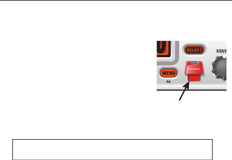
Making a distress call
2
Lift the red cover. Press and hold the DISTRESS
button for three seconds. The UM425 transmits your
boat’s location every few minutes until you receive a
response.
NOTE: If the radio displays ENTER USER MMSI,
cancel the automatic distress call and make a
normal voice distress call.
Lift the red cover
and press the
DISTRESS button.
Making a voice distress call
Speak slowly -- clearly -- calmly.
Make sure your radio is on. 1.
On the microphone, press the 2. 16/9-TRI button to switch to Channel 16 (156.8
MHz). (If the corner of the display does not show 16, press the 16/9-TRI button
again until it does.)
Press the 3. PUSH TO TALK button on the microphone and say:
"MAYDAY --MAYDAY-- MAYDAY."
Say "4. THIS IS {name or call sign of your boat}."
Say "5. MAYDAY {name or call sign of your boat}."
Tell where you are: (what navigational aids or landmarks are near, or read the 6.
latitude and longitude from your GPS).
State the nature of your distress, e.g. are you sinking, medical emergency, man 7.
overboard, on re, adrift, etc.
Give number of persons aboard and conditions of any injured persons. 8.
Estimate present seaworthiness of your ship, e.g. how immediate is the danger 9.
due to ooding or re or proximity to shore.
Briey describe your ship (length, type, color, hull). 10.
Say: "11. I WILL BE LISTENING ON CHANNEL 16."
End message by saying "12. THIS IS {name or call sign of your boat}, OVER."
Release the 13. PUSH TO TALK button and listen.
If you do not get an answer after 30 seconds, repeat your call, beginning at
step 3, above.
Making a DSC DISTRESS Call
For future reference, write your boat’s name & call sign here:
NOTE: There is no ofcial VHF DSC shore infrastructure in Australia. Vessels
tting VHF DSC equipment should realise that this equipment can only be used
for vessel - to - vessel alerting in the Australian region. There is no ofcial
shore-based infrastructure but there are a number of volunteer marine rescue
(VMR) stations that have installed VHF DSC and a check with your local VMR
should be made.
UM425 VHF OM.indd 2 28/9/11 11:55:11 AM

Making a distress call
3
UM425 VHF OM.indd 3 28/9/11 11:55:11 AM

4
Table of Contents
Making a DSC DISTRESS Call .......................................................................................2
Making a voice distress call .........................................................................................2
Table of Contents ...................................................................................... 4 (this page)
Introduction .....................................................................................................................6
Features.......................................................................................................................6
Manual overview ..........................................................................................................6
Conventions ..............................................................................................................6
Terms used in this manual ........................................................................................7
Getting Started ................................................................................................................8
What's included ....................................................................................................................... 8
Parts of the radio ..................................................................................................................... 9
Turning on the radio .............................................................................................................. 12
Setting the UIC channel mode (USA/CAN/INT) .................................................................. 12
How It Works .................................................................................................................12
Normal mode operation .............................................................................................13
Using the radio in normal mode ..............................................................................14
Normal mode with Triple and Dual Watch ..............................................................15
Scan mode.................................................................................................................16
Using the radio in scan mode .................................................................................16
Scan mode with Triple and Dual Watch ..................................................................17
Using Your Radio ..........................................................................................................18
Making a voice MAYDAY call .....................................................................................19
Setting the volume .....................................................................................................19
Setting the squelch level ............................................................................................19
Changing the channel ................................................................................................20
Making a transmission ...............................................................................................20
Boosting the transmission power ............................................................................20
Choosing Triple Watch or Dual Watch ....................................................................21
Changing display and sound options .........................................................................22
Contrast ..................................................................................................................22
Lamp adjust ............................................................................................................22
Turning the key beep on and off .............................................................................22
Setting the GPS position manually ............................................................................22
Using Digital Selective Calling (DSC) Features .........................................................24
What is DSC? ............................................................................................................24
Advanced DSC features ............................................................................................24
Getting an MMSI number...........................................................................................25
Entering MMSI numbers ............................................................................................25
Individual or user MMSI number .............................................................................25
Group MMSI number ..............................................................................................26
Using the directory .....................................................................................................27
Making DSC calls ......................................................................................................29
Calling a single station (Individual Call) ..................................................................30
Calling a particular group of stations (Group Call) ..................................................31
Calling all stations (All-Ships Call) ............................................................................... 31
Making an automatic distress call ............................................................................... 32
Canceling an automatic distress call ......................................................................32
Receiving a DSC call .................................................................................................33
Receive log ................................................................................................................33
Returning a call .......................................................................................................34
Making a Test Call (Test) ...........................................................................................35
Receiving a test call ................................................................................................36
Table of Contents
UM425 VHF OM.indd 4 28/9/11 11:55:12 AM

5
Table of Contents (Cont'd)
Table 1 - Terms used in this manual ................................................................................7
Table 2 - Rear panel connector functions ........................................................................9
Table 3 - Front panel button functions ............................................................................10
Table 4 - Microphone button functions ........................................................................... 11
Table 5 - Normal mode status messages .......................................................................14
Table 6 - Character and text entry order ........................................................................28
Table 7 - Receive log .....................................................................................................34
Table 8 - Common GPS receivers and connections ......................................................46
Table 9 - Radio specifications ........................................................................................54
Table 10 - International Channel Frequencies and Channel Tag ...................................57
Table 11 - USA Channel Frequencies and Channel Tag ................................................59
Table 12 - Canadian Channel Frequencies and Channel Tag .......................................61
Table 13 - NMEA Input Parameters ...............................................................................63
Enabling automatic test call reply ...........................................................................36
Requesting another station's position (POS Request) ..............................................36
Receiving a position request (Position Reply) ...........................................................37
Enabling automatic position reply ...........................................................................37
Sending your own position (Position Send) ................................................................38
Putting the radio into standby......................................................................................38
Disabling automatic channel switching .......................................................................39
Renaming Channels .....................................................................................................40
Installing the Hardware ................................................................................................41
Mounting the radio .....................................................................................................41
Connecting the radio..................................................................................................43
Connecting accessories.............................................................................................45
Connecting to a GPS receiver ................................................................................45
Configuring the GPS ...............................................................................................47
Connecting to a charplotter ....................................................................................48
Connecting to an external speaker .........................................................................48
Connecting to an external PA speaker ...................................................................49
Using the PA feature ...............................................................................................50
Maintenance and Troubleshooting .............................................................................51
Common questions ...............................................................................................................51
Engine Noise Suppression ................................................................................................... 53
Specifications ...............................................................................................................54
Channel and frequencies ......................................................................................................57
NMEA Operation ................................................................................................................... 63
NMEA Input ........................................................................................................................ 63
NMEA Output ..................................................................................................................... 63
Regulations and Safety Warnings ......................................................................................... 64
Basic radio guidelines ................................................................................................64
DSC: Frequently Asked Questions ............................................................................64
Antenna Selection and Installation ............................................................................65
Two Year Limited Warranty ..........................................................................................66
Mounting Bracket Template .........................................................................................67
List of Tables
UM425 VHF OM.indd 5 28/9/11 11:55:12 AM

6
Introduction
Features
Watertight Radio Housing: •
Meets the worldwide JIS6 water resistant specication means it is able to
withstand powerful water jets without damage.
Rugged Waterproof Speaker Microphone:•
With Channel Select, One-Touch 16/9 and Triple Watch Select Keys.
Meets the worldwide JIS7 waterproof specications; submersible at 1.0
metre depth for 30 minutes.
Large, dot matrix display•
Advanced DSC Class D functions, including Test Calling•
Built-in PA output•
Channel select buttons on the microphone•
Memory scan mode•
Lets you save channels to memory and monitor them in quick succession.
Transmitter Power Level Select•
Lets you boost the transmitter power from 1 watt to 25 watts for added
transmission distance.
Battery level display and tone•
Sounds an alert tone if the battery voltage goes too high or too low.
Triple Watch Operation•
Checks the emergency channel 16 and channel 9 in the background.
All marine VHF channels for the International, U.S. and Canadian •
waters
Manual overview
Conventions
This manual uses several different type styles to help you distinguish
between different parts of the radio:
• BOLD SMALL CAPITALS indicates an actual button or knob on the radio
or microphone.
• Upper and Lower case bold indicates a connector or label on the
radio.
• Italics indicate text on the display, such as menu options, prompts,
and conrmation messages.
Introduction
UM425 VHF OM.indd 6 28/9/11 11:55:12 AM

7
Introduction
DSC Digital Selective Calling. A VHF radio standard for
communicating among boats and sending automated
distress calls.
GPS Global Positioning System
NMEA National Marine Electronics Association. The
organization that governs standards for electronic
equipment used on boats. NMEA 0183 is the standard
for serial data communication used by GPS receivers.
MMSI Maritime Mobile Service Identity number. A unique,
nine-digit number that identies you and your boat
when making DSC calls. It is also used by the Coast
Guard if you send an automated distress call.
Station Any DSC radio, whether it’s operated on a boat, at a
marina, or by a shore station.
Table 1 - Terms used in the manual
UM425 VHF OM.indd 7 28/9/11 11:55:12 AM
Getting Started
8
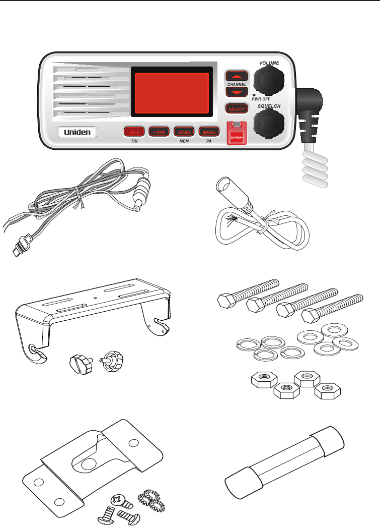
What's included
07
1 Watt INT
Memory
Scanning Channels
01,03,05,06,07,08
VHF DSC TRANSCEIVER
UM425 VHF
UM425 Radio
DC Power Cable Accessory Cable
Mounting Bracket and
knobs Mounting Hardware
Microphone Hanger and
Mounting Hardware
Spare Fuse 250V 6A
Getting Started
UM425 VHF OM.indd 8 28/9/11 11:55:13 AM
9
Getting Started
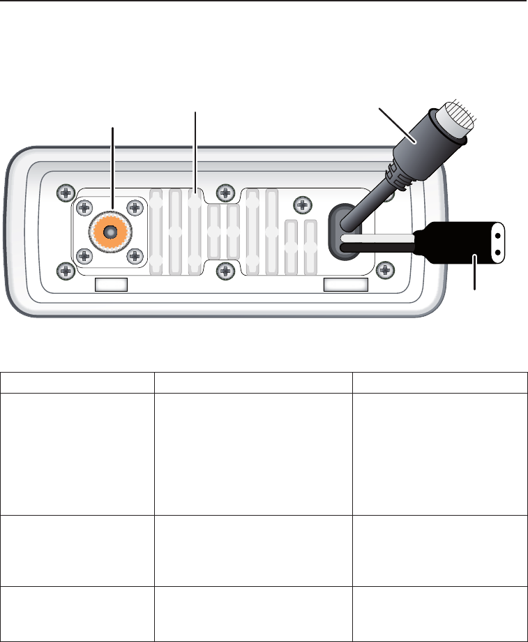
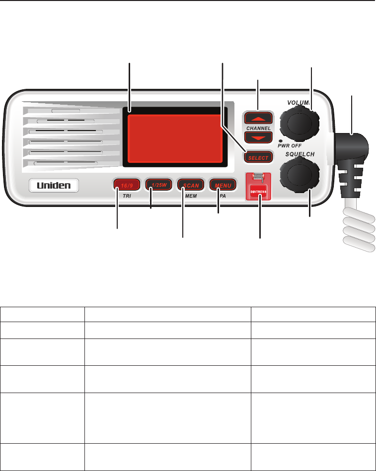
Parts of the radio
13.8V DC
ANTENNA
Antenna
connector
(SO238)
Heat sink
Power
connector
Accessory
connector
Table 2 - Rear panel connector functions
Connector Connects to For details, see
Antenna connector External VHF antenna with
a male PL259 (SO238)
connector and 50 Ω
impedance.
Minimum 1.2m, 3dB rated
antenna for sailboats, 2.4m, 6
dB rated for power boats.
Connecting the radio,
page 44.
Power connector Nominal 13.8 VDC power
supply with negative ground
(10.8 VDC to 15.6 VDC)
(Red wire +, black wire -).
Connecting the radio,
page 43.
Accessory connector GPS receiver, GPS
chartplotter, external speaker,
external PA speaker.
Connecting accessories,
page 45.
UM425 VHF OM.indd 9 28/9/11 11:55:14 AM
Getting Started
10
07
1 Watt INT
Memory
Scanning Channels
01,03,05,06,07,08
VHF DSC TRANSCEIVER
UM425 VHF
LCD
display
SELECT
button
CHANNEL UP &
DOWN buttons
VOLUME-PWR
(power) knob
(turn clockwise
to increase
volume)
Microphone
cord
16/9-TRI
(triple/
dual-watch)
button
1/25W
button
SCAN-MEM
(channel
memory)
button
MENU-PA
(public
address)
button DISTRESS
button
SQUELCH knob
(turn clockwise
to decrease
channel noise)
Button Press to... Press and hold to...
SELECT Choose an option on a menu.
CHANNEL UP Move up one channel at a time. Move quickly up the
channels.
CHANNEL DOWN Move down one channel at a time. Move quickly down the
channels.
16/9-TRI 1st press: Go to Channel 16.
2nd press: Go to Channel 9.
3rd press: Go back to the original
channel.
Go into Triple Watch or
Dual Watch mode (see
page 15).
DISTRESS Select the nature of your distress
for a distress call.
Transmit a distress call.
Table 3 - Front panel button functions
UM425 VHF OM.indd 10 28/9/11 11:55:14 AM
11
Getting Started
Button Press to... Press and hold to...
1/25W Change the transmit power (see
page 20).
MENU-PA Display the radio menu. Use the public address
(PA) function.
SCAN-MEM Start scanning the channels saved
in memory.
Save a channel into
memory or remove a
channel from memory.
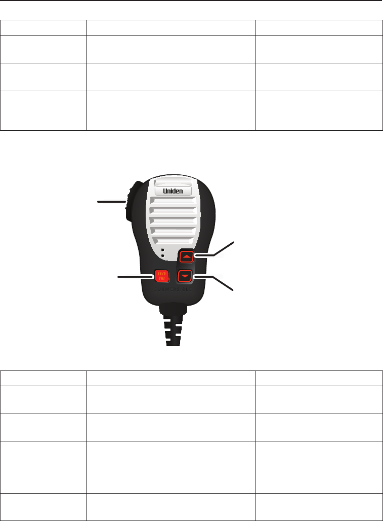
16/9
TRI
MIC
MIC
PUSH-
TO-TALK
button
16/9 TRI
(Triple/Dual-
Watch) button
▲
(up) button
(move up a channel)
▼
(down) button
(move down a channel)
Table 4 - Microphone button functions
Button Press to... Press and hold to...
▲
Move up one channel at a time. Move quickly up the
channels.
▼
Move down one channel at a time. Move quickly down the
channels.
16/9-TRI 1st press: Go to Channel 16.
2nd press: Go to Channel 9.
3rd press: Go back to the original
channel.
Go into Triple Watch or
Dual Watch mode (see
page 15).
PUSH TO TALK Cancel scanning and stay on a
channel.
Talk on a channel.
UM425 VHF OM.indd 11 28/9/11 11:55:15 AM
How It Works
12
Turning on the radio
Turn the VOLUME-PWR knob clockwise to turn on the radio. As it powers on,
the radio displays the user MMSI number; if there is no MMSI set, the radio
displays MMSI not entered.
When it powers on, the radio selects the last channel used.
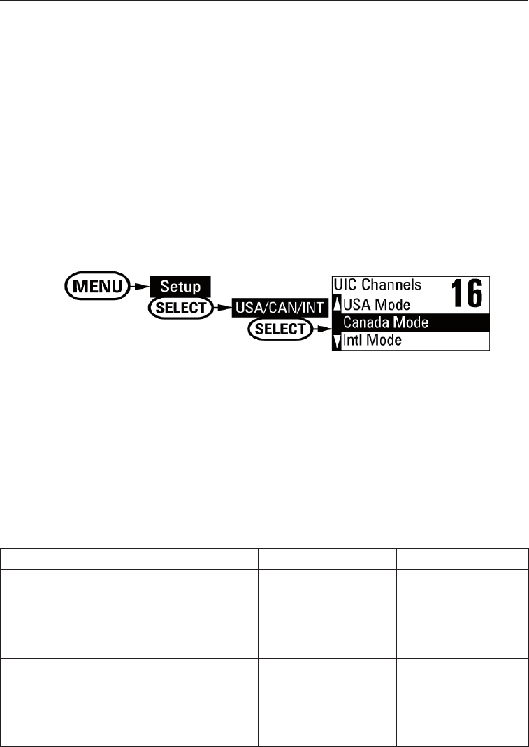
Setting the UIC channel mode (USA/CAN/INT)
NOTE: This menu selection is hidden by default. To access this feature; Turn
on the radio while holding down SCAN and
▲
buttons. The feature will
be hidden again from the menu when power is turned off. The radio comes
preset to use the UIC channels assigned for International waters. If you are
operating in an area that uses Canadian or United States UIC channels, you
will need to change the channel mode.
Press the 1. MENU-PA button to display the menu, and choose the Setup
sub-menu.
Select 2. USA/CAN/INT. The screen displays the UIC channel setup.
Highlight the channel mode you want to use: US (3. USA mode),
Canadian (Canada mode), or international (Intl mode).
Press the 4. SELECT button. The radio activates the new channel mode
and exits the menu.
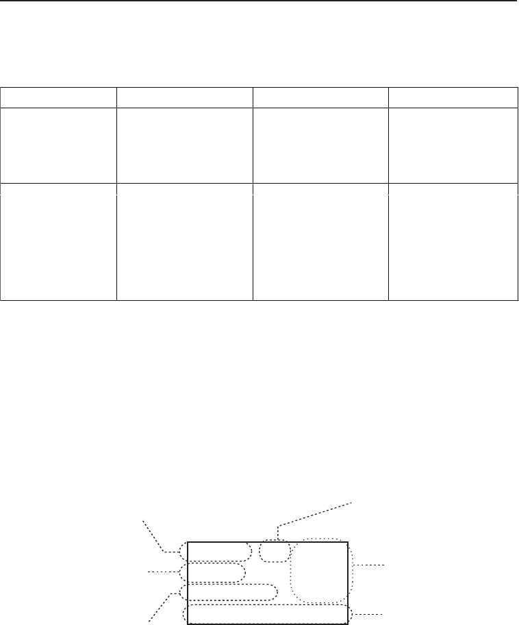
How It Works
The UM425 has two basic modes of operation:
Operation mode What it does: Use it when: To turn it on/off:
Normal mode Monitors a single
marine radio
channel and lets
you talk on that
channel.
You want to talk to
another station on a
specic channel.
(default mode)
Scan mode Monitors all the
channels you save
into memory.
You have a small
group of channels
you use most often
and want to check
them for trafc.
Press the SCAN-
MEM button.
UM425 VHF OM.indd 12 28/9/11 11:55:15 AM
13
How It Works
NOTE: You are required to monitor channel 16 whenever your boat is under-
way. You should have either Triple Watch or Dual Watch on at all times.
In addition to the two main operation modes, the UM425 also provides two differ-
ent “watch” modes which you can activate during any of the two basic modes. In
the watch modes, the radio briey checks for activity on a specic channel, then
returns to its previous mode.
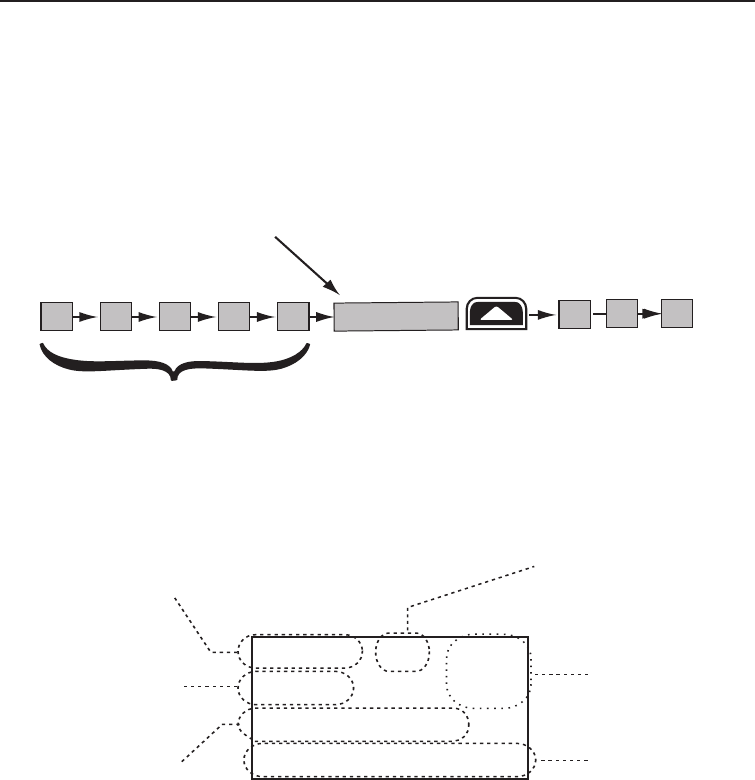
Normal mode operation
Normal mode monitors whatever channel you select, and you can transmit on
that channel also.
While using normal mode, the display lets you see the following information
(not all indicators will display at the same time):
25
Marine Operator
25 Watts INT
Memory
GPS Data OK
Transmit power
(1 W or 25 W)
Current channel
is stored in
memory
Status messages
(see the status
message table)
Current
channel
number
Current channel
name (if the name
is too long, the
name line scrolls)
Channel mode
(USA, CANadian,
or INTernational)
Watch mode What it does: Use it when: To turn it on/off:
Triple Watch Checks for activity
on channels 16
and 9 every two
seconds.
You want to monitor
a channel yet
maintain a watch on
channels 16 and 9.
Press and hold the
16/9-TRI button for
two seconds.
Dual Watch Checks for activity
on channel 16 every
two seconds.
You want to monitor
a channel yet
maintain a watch on
channel 16.
Change Triple
Watch to Dual
Watch in the setup
menu, then press
and hold the 16/9-
TRI button for two
seconds.
UM425 VHF OM.indd 13 28/9/11 11:55:15 AM

How It Works
14
Table 5 - Normal mode status messages
Message Meaning
GPS Data OK The radio is receiving valid GPS data.
Check GPS The radio is not receiving valid GPS data: check the GPS status screen and
the GPS connection.
Input Position The radio has been unable to receive valid GPS data for at least four hours;
it can no longer track your position. You need to manually input your position
(see Setting the GPS position manually on page 22).
Battery Low The battery voltage output is too low (below 10.5 VDC).
Battery High The battery voltage output is too high (above 16.0 VDC).
Triple Watch Triple Watch is turned on.
Dual Watch Dual Watch is turned on.
Using the radio in normal mode
• To transmit, press and hold the PUSH TO TALK button on the
microphone. Release the button when you are nished talking.
• For the best sound quality, hold the microphone about two inches from
your mouth while you’re talking.
• Press the CHANNEL UP button on the radio or the
▲
button on the
microphone to move up one channel at a time. Press and hold either
button to scroll quickly up the channels.
• Press the CHANNEL DOWN button on the radio or the
▼
button on
the microphone to move down one channel at a time. Press and hold
either button to scroll quickly down the channels.
• To change the transmit power, press the 1/25W button. The transmit
power switches between 1 watt and 25 watts each time you press the
1/25W button.
UM425 VHF OM.indd 14 28/9/11 11:55:15 AM
15
How It Works
09 16 09 16 09 16
Every 2 seconds, the radio
checks channels 9 & 16.
with Triple Watch on
Monitoring Channel 25
Press and hold the 16/9-TRI button (on the radio or the microphone) for two
seconds to turn Triple/Dual Watch on or off. (To change between Triple or
Dual Watch, see page 21.)
Normal mode with Triple and Dual Watch
If you activate Triple Watch while operating in normal mode, the radio checks
channels 16 and 9 every two seconds; with Dual Watch turned on, the radio
only checks channel 16. The radio will not check channels 16 or 9 while you
are actively transmitting; it waits until your transmission is nished and then
checks the channels.
UM425 VHF OM.indd 15 28/9/11 11:55:15 AM
How It Works
16
Scan mode
You can save channels into memory and then use scan mode to monitor
those channels. When the radio detects a signal on a channel, it pauses on
that channel as long as the signal is received; when the transmission stops,
the radio will continue scanning.
11
1008 1312 17
15 20
14
The radio scans about
5 channels in 1 second.
When it detects a signal, the radio stays on the
channel until you press the
CHANNEL
UP
button or the
signal stops.
Resume scan
In scan mode, you can get the following information from the display (some
indicators will not always be displayed):
1 Watt INT
Memory
Scanning Channels
01,03,05,06,07,08
07
Transmit power
last used
Channel mode
(USA, CANadian,
or INTernational)
Current
channel being
scanned
Scan list (if the
text is too long,
the line scrolls)
All scanned
channels must
be in memory
Normal scan
mode or Triple/
Dual-watch on
Using the radio in scan mode
You cannot transmit while in scan mode.•
You must have two or more channels in memory to start a scan.•
To save a channel into memory, select the channel, then press and •
hold the SCAN-MEM button for two seconds. Memory will show on the
display.
UM425 VHF OM.indd 16 28/9/11 11:55:16 AM
17
How It Works
To remove a channel from memory, set the radio to that channel, then •
press and hold the SCAN-MEM button for two seconds. Memory will no
longer show on the display.
To activate scan mode, press the • SCAN-MEM button. Press the SCAN-
MEM button again to return to the previous mode.
When the radio automatically stops on a channel, press the • CHANNEL
UP button to leave that channel and resume scanning.
To end the scan, press the microphone • PUSH TO TALK button or the
SCAN-MEM button. The radio remains on the last scanned channel.
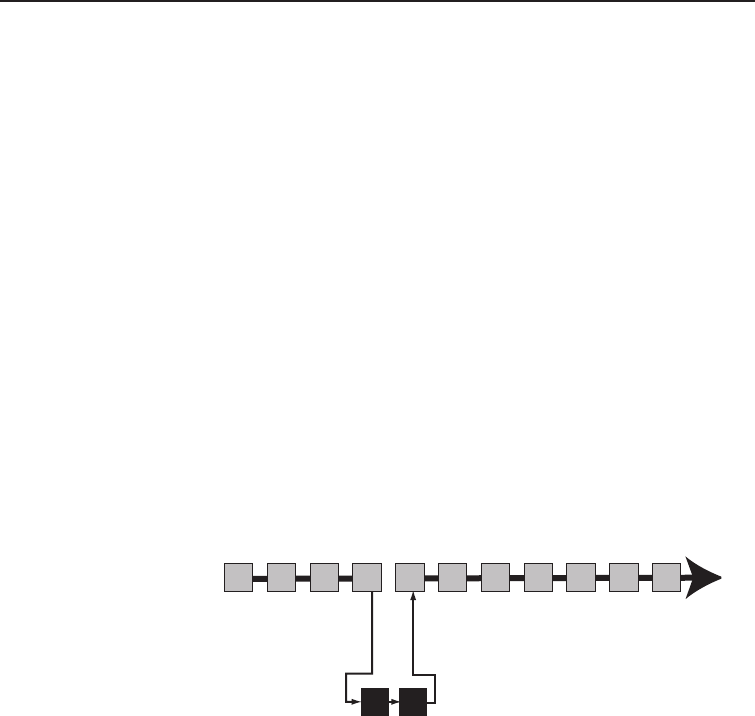
Scan mode with Triple and Dual Watch
If you activate Triple Watch while
operating in scan mode, the radio
checks channels 16 and 9 every
two seconds, then goes on to
scan the next channel; with Dual
Watch turned on, the radio only
checks channel 16:
09 16
Every 2 seconds,
the radio checks
channels 9 & 16
then goes on to
the next channel.
with Triple Watch on
Memory Channel Scan
08 252417151413121110 20
Reversed 16 & 9
UJ-SW 20061215 #17
Press and hold the 16/9-TRI button (on
the radio or the microphone) for two
seconds to turn Triple/Dual Watch on or
off. (To change between Triple or Dual
Watch, see page 21.)
UM425 VHF OM.indd 17 28/9/11 11:55:16 AM
Using Your Radio
18
Individual
Group
All Ships
POS Request
Position Send
Test
Directory
Standby
Receive Log
Exit
USA/CAN/INT*
Dual/TriWatch
GPS Setup
Auto CH SW
POS Reply
Test Reply
Channel Name
Group MMSI
User MMSI
Exit
Contrast
Lamp Adjust
Key Beep
Exit
MENU
DSC Call SELECT
Setup SELECT
System SELECT
(Close Menu)
Exit SELECT
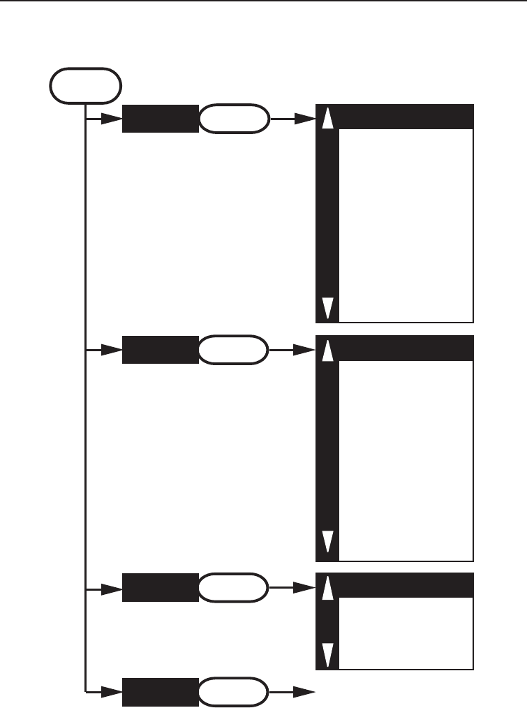
Using Your Radio
To display the radio menu, press the MENU-PA button. The menu has the
following options:
*USA/CAN/INT is hidden by default. See page 12 for instructions to access this
selection.
UM425 VHF OM.indd 18 28/9/11 11:55:16 AM
19
Using Your Radio
The currently selected item is highlighted in reversed out text. •
Press the • CHANNEL UP button on the radio or the
▲
button on the
microphone to move up a line in the menu; if you are at the top line in
the menu, the cursor jumps to the bottom of the menu.
Press the • SELECT button to choose the selected item.
Press the • CHANNEL DOWN button on the radio or the
▼
button on the
microphone to move down a line in the menu; if you are at the bottom
line of the menu, the cursor jumps to the top of the menu.
Press the • MENU-PA button to go back to the previous menu screen.
From any menu screen, choose• Exit or press the 16/9-TRI button to
close the menu screen.
Making a voice MAYDAY call
(see inside front cover)
Turn the volume knob clockwise to increase the speaker volume; turn it
counter-clockwise to decrease the volume.
Setting the volume
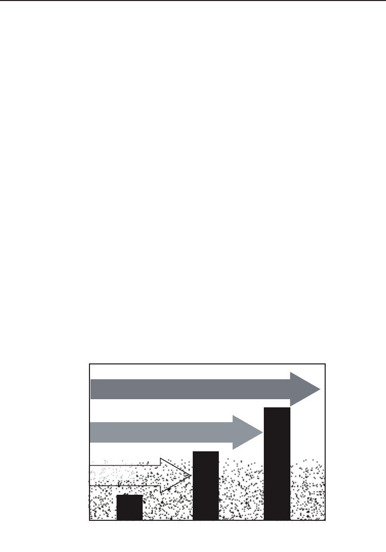
Setting the squelch level
The squelch feature reduces the level of static on the speaker by ltering out
the background channel noise. At the lowest squelch level, the speaker plays
all radio signals, including any noise on the channel. Setting the squelch
level higher lters out channel noise and lets only actual radio transmissions
through.
Weak signals
No
Squelch
Medium
Squelch
High
Squelch
Strong signals
Noise
UM425 VHF OM.indd 19 28/9/11 11:55:16 AM

Using Your Radio
20
While listening to a channel, adjust the SQUELCH knob until the noise is
ltered out and you can only hear the transmission. If you switch to a channel
with a lot of noise or with a weak transmission, you may need to adjust the
squelch level again.
NOTE: Setting the squelch level too high may prevent you from hearing
weaker transmissions. If you are having difculty hearing a transmission, try
setting the squelch level lower.
Changing the channel
Press the CHANNEL UP or CHANNEL DOWN buttons briey to scroll through the
channels one channel at a time. Press and hold the channel up or down
button to quickly scroll through the channels.
Making a transmission
To make a transmission, press and hold the microphone PUSH TO TALK button.
Release the PUSH TO TALK button when you're nished talking to let the other
party respond.
To prevent stuck microphone problems or situations where the • PUSH
TO TALK button is pushed accidentally, the radio limits your talk time
to 5 minutes in a single transmission. If you talk for over 5 minutes
continuously, the display shows RELEASE MIC BUTTON.
For the best sound quality, hold the microphone about two inches away •
from your mouth.
You cannot transmit while the radio is in scan mode.•
See the channel list on page 57 for a list of receive-only channels. •
Boosting the transmission power
In most situations, the 1 Watt transmission power is all you need. If you nd
yourself far away from other stations and have trouble getting a response,
you may need to boost the transmission power from 1 Watt to 25 Watts:
Select the channel you want to transmit on.1.
Push the 2. 1/25W button. The display shows 25 Watts in the upper left
hand corner.
The transmit power remains at 25 Watts until you change the setting 3.
back. Push the 1/25W button. The display shows 1 Watt.
NOTE: Don’t forget to change the transmission setting back to 1 Watt when
you move closer to other stations.
UM425 VHF OM.indd 20 28/9/11 11:55:16 AM
21
Using Your Radio
NOTE: By default, when you change to channel 16, the radio automatically
boosts the power to 25 Watts. Be sure to change the power back to 1 Watt if
you are not making an emergency transmission.
Some channels limit the power of transmission to 1 Watt so that there is less
interference between boaters attempting to use the channel at the same
time. If you switch to one of these channels, the radio changes back to 1 Watt
automatically. See the channel list on page 57 for a list of power-restricted
channels.
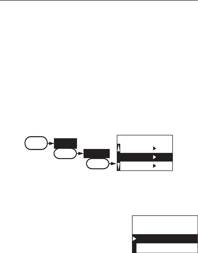
Choosing Triple Watch or Dual Watch
In Triple Watch mode, the radio briey checks channels 16 and 9 every two
seconds. In Dual Watch mode, the radio checks channel 16 only. Generally,
Triple Watch is used in areas where channel 9 is used as a hailing frequency,
while Dual Watch is used in areas where channel 16 is used for distress and
hailing. Your radio comes set to use Triple Watch; if you want to use Dual
Watch instead, you will have to select it in the setup:
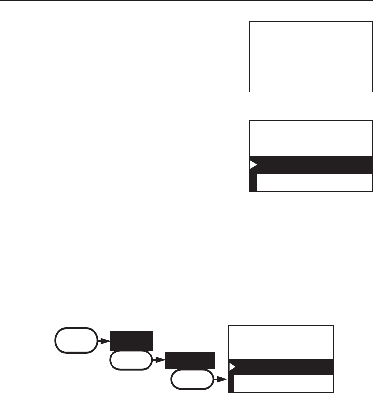
88
Dual Watch
Triple Watch
[Exit]
Dual/TriWatch
MENU Setup
SELECT
Dual/TriWatch
SELECT
Press the 1. MENU-PA button to display the menu.
Select 2. Setup and then Dual/Tri Watch.
Highlight3. Dual Watch and press the SELECT button. The radio
activates the new setting and returns to the Setup menu.
To reactive Triple Watch, repeat the procedure described above, but 4.
choose Triple Watch in step 3.
UM425 VHF OM.indd 21 28/9/11 11:55:16 AM
Using Your Radio
22
Changing display and sound options
Contrast
The UM425 display has 10 levels of contrast. To adjust the contrast, press
the MENU-PA while the radio is idle. Select System and then Contrast. Use
the CHANNEL UP and CHANNEL DOWN buttons to change the contrast to your
desired level then press the SELECT button.
To restore the default contrast setting, turn the radio off. Press the MENU-PA
button and hold it in while you turn the radio on.
Lamp adjust
The UM425 has 10 brightness levels on the display backlight. To adjust the
brightness, press the MENU-PA button while the radio is idle. Select System
and then Lamp Adjust. Use the CHANNEL UP and CHANNEL DOWN buttons to
change the brightness to your desired level then press the SELECT button.
Turning the key beep on and off
Key beep is the tone that sounds when you press a key or a button. To turn
off the key beep, press the MENU-PA while the radio is idle. Select System and
then Key Beep. Choose Off to turn off the key beep then press the SELECT
button.
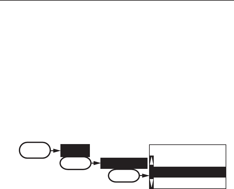
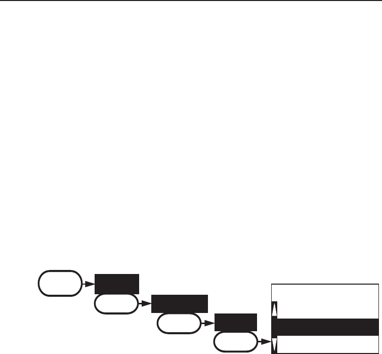
Setting the GPS position manually
If the radio is not receiving valid GPS data, the radio displays Input Position.
Follow the steps below to manually input your position.
NOTE: Be certain any manually-entered position is correct. If you enter the
wrong position and then make a DSC distress call, you will be telling the
Coast Guard to look in the wrong place.
Use the up and down
arrows to adjust each of
the values in turn.
16
--/-- 11:22U
---o --.- KT
35o 40.610 N
139o 46. 564 E
MENU Setup
SELECT
GPS Setup
SELECT
Position Set
SELECT
UM425 VHF OM.indd 22 28/9/11 11:55:16 AM

23
Using Your Radio
1. Display the menu and choose the Setup sub-menu.
2. Select GPS Setup and then choose Position Set.
3. The cursor highlights the hour. Use the CHANNEL UP and CHANNEL
DOWN buttons to set the displayed hours to match coordinated
universal time (UTC, also call Greenwich Mean Time and Zulu Time).
When the display matches UTC time, press the SELECT button.
4. The cursor moves to highlight the minutes. Use the CHANNEL UP and
CHANNEL DOWN buttons to adjust the minutes and press the SELECT-
button.
5. The cursor moves to highlight the degrees latitude. As you update
each value, the cursor moves to the next value in turn. At each number,
use CHANNEL UP and CHANNEL DOWN buttons to adjust the number and
press the SELECT button.
When you have entered the last value, the radio returns to the GPS Setup
menu.
UM425 VHF OM.indd 23 28/9/11 11:55:16 AM

Using Digital Selective Calling (DSC) Features
24
What is DSC?
Digital Selective Calling or DSC is a standard that allows you to call other
stations using their unique identication code (the Maritime Mobile Service
Identity or MMSI number), just like you would call a phone number. To call
another station, just enter that station’s MMSI number and choose the
voice channel you want to talk on. The radio uses channel 70 to transmit
your MMSI number to the other station along with the voice channel you
requested. If the other station accepts your call, both radios automatically
switch to the requested voice channel so you can talk to the other station.
DSC provides a system for automated distress calls. At the touch of a
button, the radio can transmit your MMSI number, the nature of your
distress, and your current position based on data from your GPS receiver.
The radio repeats the distress call every few minutes until it receives an
acknowledgement.
The DSC standard dedicates a VHF channel—channel 70—to digital
transmissions only. Since digital transmissions require less bandwidth voice
transmissions, channel 70 avoids the problems of busy voice channels.
Advanced DSC features
The UM425 supports the following DSC features:
Feature Menu Item Function
Individual Call Individual Contact another vessel from your directory.
Group Call Group Contact all vessels that share your group
MMSI code.
All Ships Call All Ships Broadcast to all vessels within range (used for
safety or advisory messages.)
Position Request POS Request Request the current location of another vessel.
Position Send Position Send Transmit your current location to another
vessel.
Test Call Test Make sure your radio is working and
congured correctly
Name and MMSI
Directory
Directory Store a list of 20 names and MMSI
identication codes for DSC calls.
Standby Mode Standby Automatically respond to all DSC calls with an
“Unavailable” status.
Received Call Log Receive Log Display the last 10 distress calls received by
the radio and the last 20 general calls.
Using Digital Selective Calling (DSC) Features
UM425 VHF OM.indd 24 28/9/11 11:55:16 AM

25
Using Digital Selective Calling (DSC) Features
Getting an MMSI number
In order to use DSC features, you must be assigned an MMSI number and
program that number into your radio. There are two kinds of MMSI numbers:
individual numbers for use by single boats and group numbers for use by
eets, boating organizations, event coordinators, etc.
You can get more information on MMSI numbers at these resources:
The dealer where you purchased the radio•
To Obtain an MMSI Code in Australia •
The Australian Maritime Safety Authority allocates MMSI. To apply for
an MMSI complete the MMSI Application form available for download
via www.amsa.gov.au/mmsi . This page has important information
about MMSI and DSC radio.
To Obtain an MMSI Code in NZ•
To obtain an MMSI for a VHF Recreational Radio contact the Ministry
of Economic Development - Radio Spectrum Management at;
Email: info@rsm.govt.nz or free phone 0508 776 4630.
The DSC radio owner should indicate they are seeking an MMSI for a
VHF Recreational Radio and would then need to supply the following;
• Name • VHF Call sign • Vessel Name • Vessel Details
The MMSI given will then be a unique number which will conform to the
ITU format.
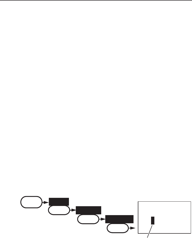
Entering MMSI numbers
Individual or user MMSI number
Follow the steps below to enter your individual or user MMSI number into the
radio:
NOTE: Be sure you have the correct User MMSI number before entering it
in the radio. The radio only allows you to enter the user MMSI once. If you
need to enter the User MMSI number for the second time, contact customer
service (see page 66 for contact information).
16
User MMSI
Use the up and down
arrows to adjust each of
the nine digits in turn.
0
_______
MENU Setup
SELECT
User MMSI
SELECT
1. Display the menu and choose the Setup sub-menu.
2. Select User MMSI. If an MMSI number was entered previously, the
screen displays it.
UM425 VHF OM.indd 25 28/9/11 11:55:17 AM
Using Digital Selective Calling (DSC) Features
26
3. Use the CHANNEL UP and CHANNEL DOWN buttons to change the rst of
the nine digits; the CHANNEL UP button increases the number and the
CHANNEL DOWN button decreases the number.
4. When the rst digit is correct, press the SELECT button. The cursor
moves to the next digit. Enter the remaining eight digits of the MMSI
number in the same way.
5. When the ninth digit is correct, press the SELECT button. The radio
displays the new MMSI number and asks you to conrm.
NOTE: Be sure you entered the number correctly before conrming the entry.
You can only save the user MMSI once. If the radio displays Cannot change
over 1 time, contact customer service (see page 66 for contact information).
6. To save this MMSI number, select Yes. To cancel this MMSI number,
select No. The radio returns to the Setup menu.
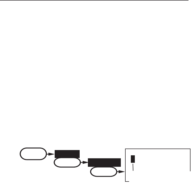
Group MMSI number
You can change the group MMSI number as often as you want. Follow the
steps below to enter a group MMSI number into the radio:
16
00
______
Group MMSI
Use the up and down
arrows to adjust the
remaining eight digits.
MENU
Setup
SELECT
Group MMSI
SELECT
1. Display the menu and choose the Setup sub-menu.
2. Select Group MMSI. If a group MMSI number was entered previously,
the screen displays it.
3. Group MMSI numbers always start with a 0, so that digit is already
entered for you. Use the CHANNEL UP and CHANNEL DOWN buttons to
change the second of the nine digits; the CHANNEL UP button increases
the number and the CHANNEL DOWN button decreases the number.
4. When the second digit is correct, press the SELECT button. The cursor
moves to the next digit. Enter the remaining seven digits of the MMSI
number in the same way.
UM425 VHF OM.indd 26 28/9/11 11:55:17 AM
27
Using Digital Selective Calling (DSC) Features
16
00
______
Group MMSI
Use the up and down
arrows to adjust the
remaining eight digits.
MENU
Setup
SELECT
Group MMSI
SELECT
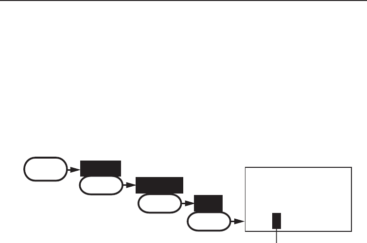
Using the directory
The directory lets you store up to 20 MMSI numbers of other stations so you
can call them quickly.
Follow the steps below to edit the MMSI numbers in your directory:
Use the up & down arrows to
scroll through the alphabet
for each character.
JOHN
123456789
16
MMSI
Name
MENU
DSC Call
SELECT
Directory
SELECT
New
SELECT
5. When the ninth digit is correct, press the SELECT button. The radio
displays the new MMSI number and asks you to conrm.
6. To save this MMSI number, select Yes. To cancel this MMSI number,
select No. The radio returns to the Setup menu.
1. Display the menu and choose the DSC Call sub-menu.
2. Select Directory. The screen displays any previously-entered MMSI
numbers and names.
3. To add a new MMSI number to the directory, select New.
4. The radio prompts you to enter the nine-digit MMSI number. Use the
CHANNEL UP and CHANNEL DOWN buttons to change the rst digit; the
CHANNEL UP button increases the number and the CHANNEL DOWN
button decreases the number.
5. When the rst digit is correct, press the SELECT button. The cursor
moves to the next digit. Enter the remaining eight digits of the MMSI
number in the same way.
6. When the ninth digit is correct, press the SELECT button.
7. The radio prompts you to enter a name for this MMSI number; the
name is what you will see in the directory list. Each name can be up
to 12 characters. Use the CHANNEL UP and CHANNEL DOWN buttons
to change the rst character. The channel buttons scroll through the
available characters according to the following table:
UM425 VHF OM.indd 27 28/9/11 11:55:17 AM
Using Digital Selective Calling (DSC) Features
28
CHANNEL UP button CHANNEL DOWN button
Capital letters (A through Z) One blank space
Lower-case letters (a through z) Numbers (0 through 9)
Punctuation (/ ‘ + -) Punctuation (/ ‘ + -)
Numbers (0 through 9) Lower-case letters (a through z)
One blank space Capital letters (A through Z)
Table 6 - Character and text entry order
8. When the rst character is correct, press the SELECT button. The cursor
moves to the next character. Enter the remaining 11 characters of
the name. If the name is shorter than 12 characters, press and hold
the SELECT button to complete the name entry. (If you press and hold
the SELECT button without entering a name, the radio uses the MMSI
number in the directory list.)
9. When you nish entering the name, the radio displays the new MMSI
number and name and asks you to conrm. To save this directory
entry, select Yes; to cancel this directory entry, select No. The radio
returns to the directory list.
10. To change an existing directory entry, select the entry you want to
change.
11. To delete the directory entry, select Delete. To edit the code, select
Edit, then use CHANNEL UP and CHANNEL DOWN buttons to edit the
MMSI number and the name.
12. When you are satised with the directory list, select Exit to close the
menu screen.
UM425 VHF OM.indd 28 28/9/11 11:55:17 AM
29
Using Digital Selective Calling (DSC) Features
CHANNEL UP button CHANNEL DOWN button
Capital letters (A through Z) One blank space
Lower-case letters (a through z) Numbers (0 through 9)
Punctuation (/ ‘ + -) Punctuation (/ ‘ + -)
Numbers (0 through 9) Lower-case letters (a through z)
One blank space Capital letters (A through Z)
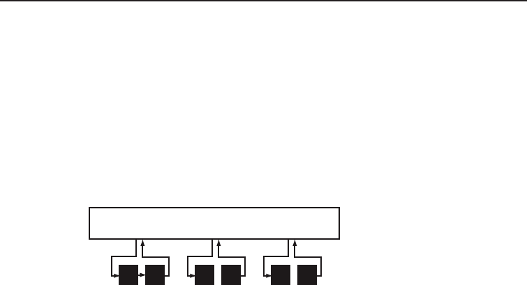
Making DSC Calls
There are essentially four different types of DSC voice calls:
Call type What it does When to use it
Distress Alerts all stations that you need
assistance and sends them your
current position.
In an emergency only.
Individual Calls a single station using the
User MMSI.
Any time you want to talk to
another station.
Group Calls all the stations that have the
same Group MMSI as yours.
Any time you want to talk with
the whole group you are traveling
with at the same time.
All ships Calls all stations in range of your
radio.
Safety warnings (e.g., debris
in the water) or an urgency
situation.
All ships call
Group
call
Individual
call
All ships call
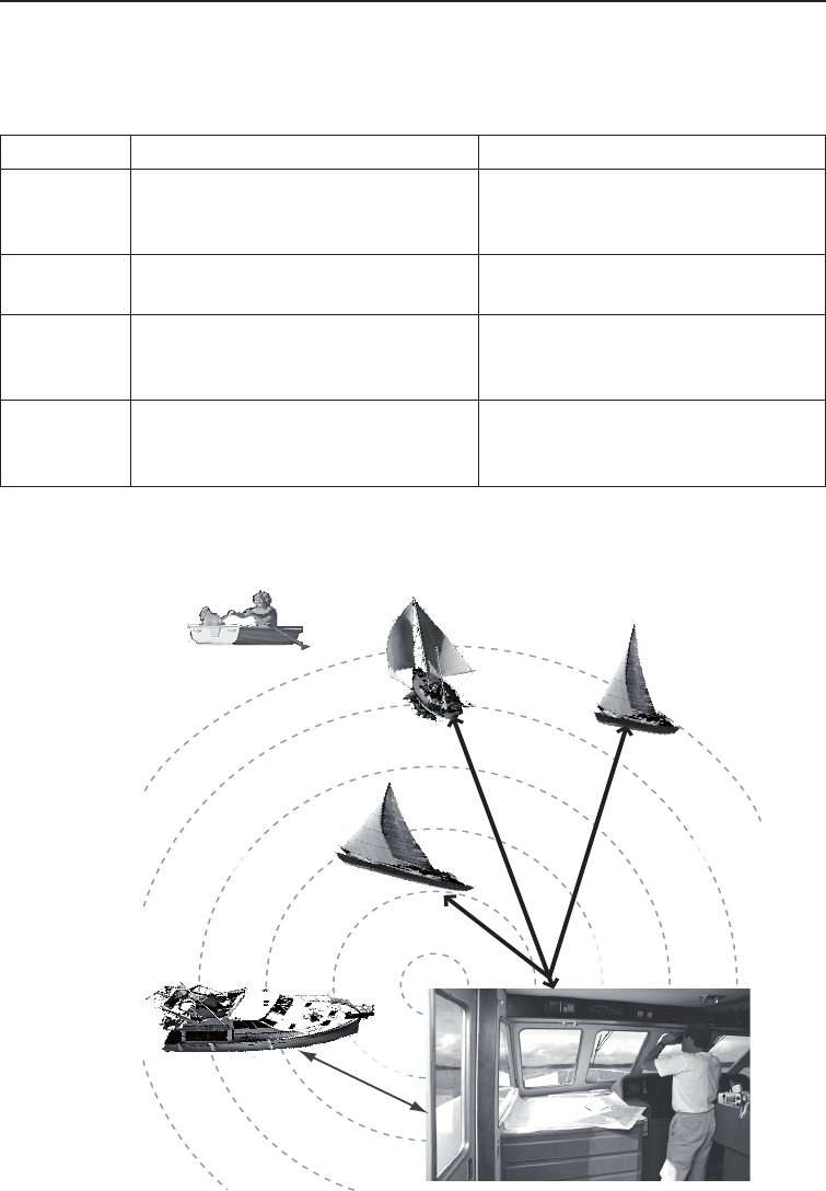
For examples of how you might use different call types, see the diagram
below:
(dotted circles) (dotted circles)
UM425 VHF OM.indd 29 28/9/11 11:55:17 AM

Using Digital Selective Calling (DSC) Features
30
Suppose you are coordinating safety for a sailboat race. Before the race
starts, you instruct all the racers to enter your group MMSI number into their
radios. During the race:
• Throughout the race, you use group calling to update the racers on the
time, race status, and any course corrections.
• A power boat full of spectators comes a little too close to the race path.
You use individual calling to contact the power boat and advise them to
stay clear of the race.
• You see a rowboat entering the area, but since it doesn’t have a radio,
you can’t communicate with the rowboat. You use all ships calling to
alert all the other boats in the area of the possible danger.
Calling a single station (Individual Call)
To call a single station with DSC, follow the steps below:
Press the 1. MENU-PA button to display the menu.
Choose the 2. DSC Call sub-menu, then select Individual.
The radio displays the names listed in your directory; use 3. CHANNEL UP
and CHANNEL DOWN buttons to highlight the directory entry you want to
call and press the SELECT button.
If you want to call a station that is not in your directory, select Manual.
The radio prompts you to enter the MMSI number you want to call.
Enter the MMSI number the same way you enter directory entries (see
page 27) Enter all nine digits and press the SELECT button.
The radio prompts you to select a response channel. Use 4. CHANNEL UP
and CHANNEL DOWN buttons to scroll through the available channels.
When you reach the channel you want to use for a response, press the
SELECT button.
The radio displays the MMSI number you are about to call and asks 5.
you to conrm. If you want to call the displayed MMSI number, select
Send. To cancel the call, select Cancel.
The radio automatically switches to channel 70 to transmit the call 6.
request.
UM425 VHF OM.indd 30 28/9/11 11:55:17 AM

31
Using Digital Selective Calling (DSC) Features
When the other station accepts the call, both radios switch to the se-•
lected response channel for voice transmission.
If the other station cannot respond on the channel you selected, the •
radio displays Not support CH.
Calling a particular group of stations (Group Call)
Group calling calls all the stations that share your group MMSI. You must
have a group MMSI programmed into the radio to make a group call, and
the stations (boats) you are calling must have this same group MMSI
programmed into their radios.
Calling all stations (All-Ships Call)
All ships calling contacts all DSC radios within range of your boat. You should
only use all ships calling in the event of a Safety warning (such as debris in
the water) or to request assistance in an Urgency (any situation where your
vessel has a serious problem but is not yet in distress).
Open the menu and select the 1. DSC Call sub-menu.
Select 2. All Ships, and then choose whether this is an Urgency call or a
Safety call.
The radio asks you to conrm the call. Select 3. Send to continue with the
call or select Cancel to cancel the call.
The radio automatically switches to channel 70 to transmit the call 4.
request then automatically switches to channel 16, the designated
response channel for all-ships calling.
Press the 1. MENU-PA button to display the menu.
Choose the 2. DSC Call sub-menu and select Group.
The radio prompts you to select a response channel. Use the 3. CHANNEL
UP and CHANNEL DOWN buttons to scroll through the available channels.
When you reach the channel you want to use for a response, press the
SELECT button.
The radio asks you to conrm the call. Select 4. Send to continue with the
call or select Cancel to cancel the call.
The radio switches to channel 70 to transmit the call request then 5.
automatically switches to the selected response channel.
UM425 VHF OM.indd 31 28/9/11 11:55:17 AM

Using Digital Selective Calling (DSC) Features
32
Making an automatic distress call
If you have programmed your MMSI number, the UM425 can transmit an
automated distress call with your current location and nature of the distress.
The radio then monitors the channel 16 for a response and repeats the
distress call every few minutes until it receives an acknowledgement.
To send an automatic distress call, press and hold the DISTRESS button
for three seconds. If no MMSI number has been programmed, the radio
prompts you to enter your MMSI number.
If you want to include the nature of your distress in the distress call, use the
distress procedure below:
1. Press the DISTRESS button.
2. The radio displays the list of distress conditions; use the CHANNEL UP
and CHANNEL DOWN buttons to highlight the nature of your distress,
then press and hold the DISTRESS button for three seconds.
• Undesignated
• Fire
• Flooding
• Collision
• Grounding
• Capsizing
• Sinking
• Adrift
• Abandoning
• Piracy/Armed
• Overboard
3. If no MMSI number has been programmed, the radio prompts you to
enter your MMSI number.
Canceling an automatic distress call
While the radio is waiting for a response, it gives you the option of canceling
the call. To cancel the distress call, highlight Cancel and press the SELECT
button.
UM425 VHF OM.indd 32 28/9/11 11:55:17 AM
33
Using Digital Selective Calling (DSC) Features
Receiving a DSC call
If your radio receives an individual DSC call from another station, it sounds
an incoming call tone and displays the name or MMSI number of the station
calling you. To respond to the call, select Send: Able-Comply; the radio sends
an acknowledgement and automatically switches to the designated response
channel. To reject the call, select Send: Unable-Comply; the radio advises the
other station that you are unable to respond to the call.
If the DSC request contains a response channel that you are not allowed to
use, the radio displays Not Support CH; your only response option is Send:
Unable-Comply.
If the radio receives a group or all ships call, it sounds an incoming call tone
and automatically switches to the designated response channel.
Receive log
Just like your telephone’s caller ID list, your radio keeps track of the calls you
receive but do not answer. The receive log is useful if you have been off your
boat or away from your radio and want to see who has tried to contact you.
The radio displays the last 10 distress calls and the last 20 non-distress calls
that it received.
88
123456789
987654321
[Exit]
Distress Log
MENU
DSC Call
SELECT
Receive Log
SELECT
Distress
SELECT
Press the 1. MENU-PA button to display the menu.
Choose the 2. DSC Call sub-menu and then select Receive Log.
Select 3. Distress to see the last 10 distress call received by the radio.
Select Other to see the last 20 normal calls received by the radio, then
choose from Individual, Group or All Ships calls.
Calls are listed in the order they were received, with the newest call 4.
shown rst. The display blinks if there are new calls you have not
reviewed.
Select the call you want to see the details of. Use 5. CHANNEL UP and
CHANNEL DOWN buttons to see all of the information. The log displays
different information depending on type of call received. See the table
below for the information stored for each type of call:
UM425 VHF OM.indd 33 28/9/11 11:55:17 AM

Using Digital Selective Calling (DSC) Features
34
DSC Call Type Receive Log Information
Distress MMSI (or name), position, time, nature code.
Distress Acknowledge MMSI (or name), distress MMSI, position, time,
nature code.
Distress Relay MMSI (or name), distress MMSI, position, time,
nature code.
Distress Relay Acknowledge MMSI (or name), distress MMSI, position, time,
nature code.
Geographical MMSI (or name), category code.
All Ships MMSI (or name), category code.
Group MMSI (or name), category code.
Individual MMSI (or name), category code.
Individual Acknowledge MMSI (or name), Completed/Unattended, category
code.
Test MMSI (or name), category code.
Test Acknowledge MMSI (or name), category code.
Pos Reply MMSI (or name), position, time, category code.
Pos Request MMSI (or name), category code.
Pos Send MMSI (or name), position, time, category code.
6. Press the MENU-PA button to exit the detail screen and return to the log
menu.
7. From the log menu, select Exit to close the receive log and return to
the mode you were in.
Returning a call
You can return individual calls directly from the receive log. From the call
detail screen, press the CHANNEL DOWN button until Call Back appears at the
bottom of the display. Press the SELECT button to return that station's call.
Table 7 - Receive Log
UM425 VHF OM.indd 34 28/9/11 11:55:18 AM
35
Using Digital Selective Calling (DSC) Features
Making Test Calls (Test)
Press the 1. MENU-PA button to display the menu.
Choose the 2. DSC Call sub-menu, then select Test.
The radio displays the names listed in your directory; use the 3. CHANNEL
UP and CHANNEL DOWN buttons to highlight the directory entry you want
to send a test call to and press the SELECT button.
If you want to send a test call to a station that is not in your directory,
select Manual. The radio prompts you to enter the MMSI number you
want to call. Enter the MMSI number the same way you enter directory
entries (see page 27). Enter all nine digits and press the SELECT
button.
The radio displays the MMSI number you 4.
are about to call and asks you to conrm.
If you want to call the displayed MMSI
number, select Send. To cancel the call,
select Cancel.
The radio automatically switches to chan-5.
nel 70 to transmit the test call request,
then switches back to the last-used channel.
You can use the test call feature to make sure your radio is working and
congured correctly. To avoid overloading coastal receiving stations, you
should limit test calls to these stations to once a week.
NOTE: Many coastal stations have specic frequencies and MMSI numbers
you should use for making test calls. Be sure to check with the coastal station
before making a DSC test call.
16
[Manual]
John Henry
Sam Adams
Test
MENU
DSC Call
SELECT
Test
SELECT
16
Send
Cancel
Test
123456789
UM425 VHF OM.indd 35 28/9/11 11:55:18 AM
Using Digital Selective Calling (DSC) Features
36
Requesting another station's position (POS Request)
Anytime you need to know where another boat currently is—to nd your
boating partners, to respond to a request for assistance, etc.—you can send
a position request to their radio:
When the other station acknowledges 6.
the test call, the radio displays an ac-
knowledgement screen.
Receiving a test call
When another station sends you a test call,
the radio displays the test request screen:
To acknowledge the test call, select Reply
To reject the test call, select Cancel.
Enabling automatic test call reply
If you want the radio to automatically reply to all test call, you can enable
automatic test call reply.
Press the 1. MENU-PA button to display the menu.
Select 2. Setup and then Test Reply.
Highlight 3. Auto and press the SELECT button. The radio will
automatically send an acknowledgement when it receives a test call.
To disable automatic test call reply, repeat the steps above and select 4.
Manual.
16
Test
Acknowledged
123456789
Completed
16
Auto
Manual
Test Reply
MENU
Setup
SELECT
Test Reply
SELECT
16
Reply
Cancel
Test
123456789
UM425 VHF OM.indd 36 28/9/11 11:55:18 AM

37
Using Digital Selective Calling (DSC) Features
Press the 1. MENU-PA button to display the menu.
Choose the 2. DSC Call sub-menu, then select POS Request.
The radio displays the names listed in your directory; use 3. CHANNEL UP
and CHANNEL DOWN buttons to highlight the directory entry you want to
contact and press the SELECT button. If you want to contact a station
that is not in your directory, select Manual. The radio prompts you to
enter the MMSI number you want to call. Enter the MMSI number the
same way you enter directory entries (see page 27). Enter all nine
digits and press the SELECT button.
The radio displays the MMSI number you are about to contact and 4.
asks you to conrm. If you want to request the position of the displayed
MMSI number, select Send. To cancel the request, select Cancel.
When the other station responds, the radio displays the MMSI number, 5.
the longitude, and the latitude of the other station. If your radio is
connected to a chartplotter through the NMEA OUT connection (see
page 48), the position information will also be displayed on the plotter
screen.
If the other station does not have valid GPS data, the radio displays 6. No
Position.
Receiving a position request (Position Reply)
When another station requests your current position, the radio displays the
following screen:
88
Reply
Cancel
POS Request
JOHN HENRY
To send your current position to the other
station, select Reply; the radio transmits your
latitude and longitude to the other station. If
you select Reply but the radio does not have
valid GPS data, it transmits the reply code
with No Position.
To reject the position request, select Cancel.
Enabling automatic position reply
If you want the radio to automatically transmit your current position whenever
it receives a position request, you can enable automatic position reply. Most
boaters activate automatic position reply for safety reasons or because they
subscribe to a marine towing service. Sometimes—for example, in some
competitive situations--you may not want other stations to get your position
without your manual conrmation
UM425 VHF OM.indd 37 28/9/11 11:55:19 AM

Using Digital Selective Calling (DSC) Features
38
Press the 1. MENU-PA button to display the menu.
Select 2. Setup and then POS Reply.
Highlight 3. Auto and press the SELECT button. The radio will
automatically transmit your position when it receives a position request.
To disable automatic position reply, repeat the steps above and select 4.
Manual.
Sending your own position (Position Send)
If your radio is connected to a GPS receiver, you can send your boat’s
position to someone else. If you are requesting assistance or using an all
ships call to give a safety warning, you can send your current position so
other stations know where you are:
Press the 1. MENU-PA button to display the menu.
Choose the 2. DSC Call sub-menu, then select Position Send.
The radio displays the names listed in your directory; use 3. CHANNEL UP
and CHANNEL DOWN buttons to highlight the directory entry you want to
contact and press the SELECT button. If you want to contact a station
that is not in your directory, select Manual. The radio prompts you to
enter the MMSI number you want to call. Enter the MMSI number the
same way you enter directory entries (see page 27). Enter all nine
digits and press the SELECT button.
The radio displays the MMSI number you are about to contact and 4.
asks you to conrm. If you want to transmit your position to the
displayed MMSI number, select Send. To cancel the transmission,
select Cancel.
The radio transmits your MMSI number, your longitude, and your 5.
latitude to the other station.
Putting the radio into standby
If you are leaving your radio or do not wish to answer any DSC calls, you can
put your radio in standby mode. If your radio receives an individual call, it will
automatically respond with a message that indicates your radio is currently
"Unattended" on the display of the calling radio. Follow the steps below to put
your radio in standby:
UM425 VHF OM.indd 38 28/9/11 11:55:19 AM

39
Using Digital Selective Calling (DSC) Features
88
Unattended
1 Watt INT
Memory
DSC Standby
MENU DSC Call
SELECT
Standby
SELECT
1. Display the menu and choose the DSC Call sub-menu.
2. Select Standby to place your radio in standby mode. The radio displays
the standby screen, above.
3. To cancel standby and return to the mode your radio was in, press any
button.
Disabling automatic channel switching
If you are involved in a bridge-to-bridge call, you may not want the radio to
automatically switch channels when it receives a DSC call. In cases like this,
you can disable automatic channel switching. If you receive an individual call,
the radio will respond with an unattended code, just as if the radio were in
Standby.
Press the 1. MENU-PA button to display the menu.
Select 2. Setup and then Auto CH SW.
Highlight 3. Off and press the SELECT button. The radio will not
automatically switch channels until you reactivate this feature.
NOTE: Use this feature with caution. Deactivating automatic switching and
then forgetting it can make it hard for you to receive DSC calls.
UM425 VHF OM.indd 39 28/9/11 11:55:19 AM

Renaming Channels
40
If you discover that a marine radio channel has a different common name
in your local area, you can change the name of that channel to make it
easier for you to use (see the channel list on page 57 for the default channel
names). To rename a channel, follow the steps below:
Display the menu and choose the 1. Setup sub-menu.
Select 2. Channel Name. The screen displays the list of channels.
Use 3. CHANNEL UP and CHANNEL DOWN buttons to highlight the channel
you want to change and press the SELECT button.
Select 4. Rename to enter a new name for this channel. The radio
prompts you to enter a new name for this channel. Each name can be
up to 12 characters. Use the CHANNEL UP and CHANNEL DOWN buttons
to change the rst character. (See Table 6 Character and text entry
order on page 28 for the available characters and the order in which
they scroll).
When the rst character is correct, press the 5. SELECT button. The cursor
moves to the next character. Enter the remaining 11 characters of the
name. If the name is shorter than 12 characters, press and hold the
SELECT button to complete the name entry.
When you nish entering the name, the radio displays the new channel 6.
name and asks you to conrm. To save this new channel name, select
Yes; to cancel the change, select No. The radio returns to the channel
list.
To restore a channel back to its original name, select the channel and 7.
choose Default.
When you are satised with the channel list, select 8. Exit to close the
menu screen.
Renaming Channels
UM425 VHF OM.indd 40 28/9/11 11:55:19 AM
41
Installing the Hardware
Mounting the radio
The UM425 can sit at any angle in the mounting bracket so it can easily
accommodate the best location. First, determine the best place to mount the
radio. For optimum performance, nd a location that can:
• Properly support the weight of the radio, approximately 2 pounds or
0.9 kilograms. You may need to use some type of anchor with the
mounting screws to hold the radio, depending on the surface.
• Keep the battery leads as short as possible.
• Keep the antenna lead-in wire as short as possible.
• Allow free air ow around the heat sink on the rear of the radio.
• Avoid interference with the ship’s compass.
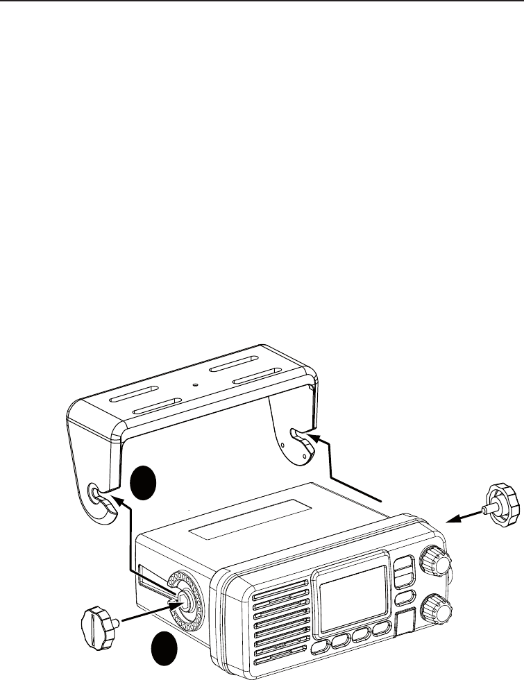
Install the radio into the mounting bracket, and connect the 1. power
cable and accessory cable.
1
2
Step 1:
Slide the radio
into the mounting
bracket.
Step 2:
Tighten the mounting knobs
to secure the radio in place.
Installing the Hardware
UM425 VHF OM.indd 41 28/9/11 11:55:20 AM
Installing the Hardware
42
Position the radio into the desired location. Mark the edges of the 2.
bracket on the mounting surface.
Remove the mounting bracket drill template from the back of the 3.
manual, and use the template to mark the drill holes on the mounting
surface.
Drill the holes for the mounting bracket; be sure to follow any special 4.
requirements of the mounting surface.
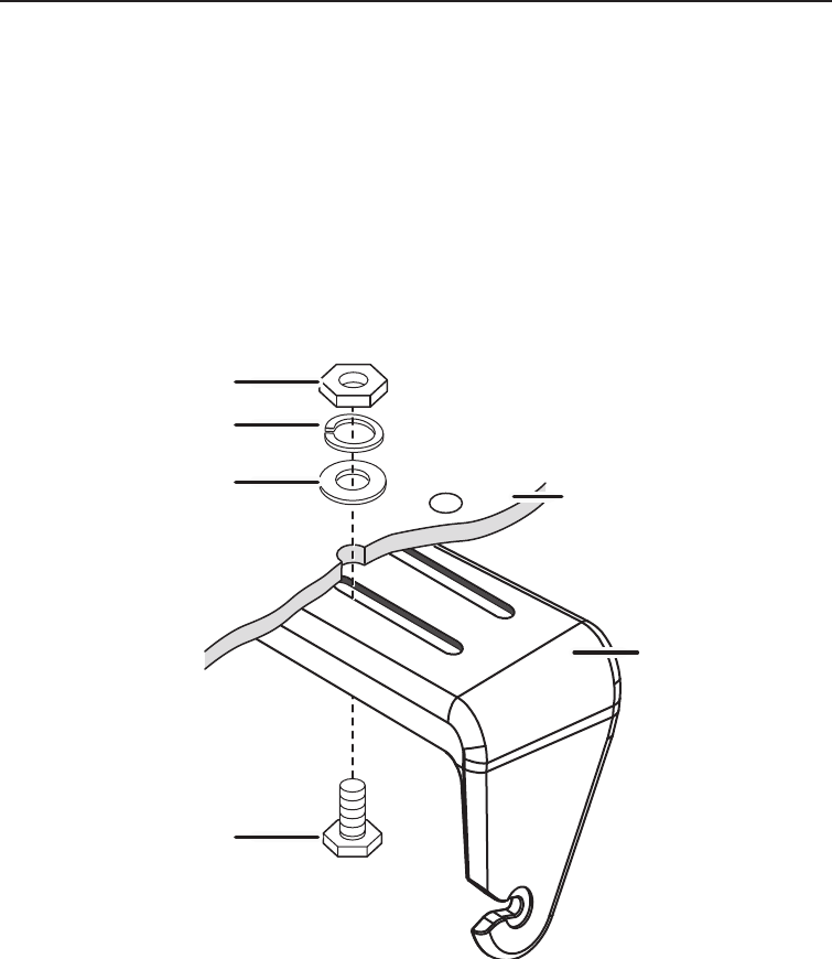
Remove the bracket from the radio, and use the mounting hardware to 5.
secure the bracket to the mounting surface.
Hex bolt
Washer
Spring washer
Hex nut
Mounting
bracket
Mounting
surface
Install the radio back into the mounting bracket.6.
UM425 VHF OM.indd 42 28/9/11 11:55:20 AM
43
Installing the Hardware
Connecting the radio
To operate correctly, your UM425 requires two electrical connections:
• providing it with power from the boat’s electrical system
• connecting a VHF-FM marine antenna to the antenna connector
Power supply requirements VHF antenna requirements
Nominal 13.8 VDC power supply with
a negative ground (10.8 VDC to 15.6
VDC).
Power leads should be kept as short
as possible. A direct connection to the
power supply is ideal.
Minimum of #14 AWG copper wire for
extensions up to 6m, 12 AWG wire for
extensions from 6m to 10m, or 10 AWG
wire for extensions from 10 to 18m
Male PL-259 connector
50 Ω impedance
Minimum 1.2m, 3 dB rated antenna for
sailboats or 2.4m, 6dB rated antenna for
powerboats
Minimum RG-58 lead-in wire for antenna
leads up to 6m to 10m, RG-8X for an-
tenna leads from 6m to 10m, or RG-8U
for antenna leads from 10m to 18m.
13.8V DC
Power
cable
Power
connector
Black wire
(-)
Red wire
(+)
UM425 VHF OM.indd 43 28/9/11 11:55:21 AM
Installing the Hardware
44
Connect the BLACK wire of the included 1. power cable to the
NEGATIVE (-) side of your power source.
Connect the RED wire of the included 2. power cable to the POSITIVE
(+) side of your power source.
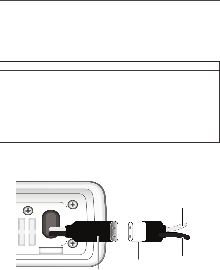
Connect the 3. power cable to the power connector on the back of the
UM425. (The power connector only ts one way.)
NOTE: To extend the life of the radio, use waterproof tape to seal
electrical connections.
Install your antenna according to the manufacturer’s instructions. 4.
See Antenna Selection and Installation on page 65 for more details. 5.
Connect the PL-259 connector from the antenna lead-in wire to the 6.
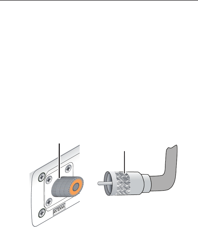
SO238 connector labeled ANTENNA on the back of the UM425.
Radio connector,
SO238 (female
PL-259)
Antenna lead-in
connector,
male PL-259
UM425 VHF OM.indd 44 28/9/11 11:55:21 AM
45
Installing the Hardware
Connecting accessories
Connecting to a GPS receiver
If you connect the radio to a GPS receiver, the radio can automatically
transmit your current position during an automated distress call or during a
normal DSC call.
The UM425 supports a standard NMEA0183 input from a GPS receiver.
Follow the steps below to connect the UM425 to your GPS receiver:
13.8V DC
Accessory
cable
Accessory
connector
Green: GPS Data IN (+)
Bare wire: Ground/ GPS Data IN (-)
Black: Ext. Speaker (-)/GND
Red: External Speaker (+)
Brown: PA Speaker (+)
Blue: PA Speaker (-)/ GND
Orange: NMEA OUT (-)
Yellow: NMEA OUT (+)
Line up
arrows to
connect
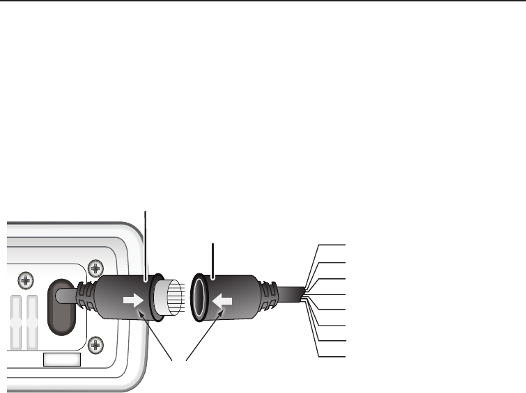
Disconnect the 1. accessory cable from the accessory connection on the
radio.
Connect the BARE wire of the included 2. accessory cable to the
GROUND WIRE on your GPS receiver.
Connect the GREEN wire of the included 3. accessory cable to the GPS
DATA OUTPUT WIRE on your GPS receiver. On page 46 is a table of
common GPS receivers and the proper connections:
NOTE: If not using the accessory connector make sure the cap is rmly secured.
UM425 VHF OM.indd 45 28/9/11 11:55:22 AM

Installing the Hardware
46
Table 8 - Common GPS receivers and connections
GPS Manufacturer Model Number(s)
GPS NMEA0183 OUTPUT
Wire Color
(Connect to GREEN WIRE
on UM425)
Ground Wire Color
(connect to BARE
WIRE on UM425)
Furuno GP1650, GP1850 White Black
Furuno GP30, GP36 White Blue
Garmin Fixed Mount
Models
Blue Black
Garmin Portable Models Brown Black
JRC 100 Series Green Black
JRC 200 Series White Black
JRC GPS500 Yellow Green
Lowrance / Eagle Fixed Mount
Models
White Black
Lowrance / Eagle Portable Models Orange Black
Magellan Fixed Mount
Models
Gray Black
Magellan Portable Models Orange Black
Northstar All Models Yellow Black
RayMarine 420 Yellow Brown
RayMarine 520 / 620 Blue Brown
RayMarine RL Series White Brown
Simrad All Models White Brown
Sitex Neptune, Nautilus Gray Brown
Standard CP150 / CP150C Green Yellow
Be certain all wire connections are secure and that all open wires are 4.
adequately covered.
If you are nished connecting all external accessories, line up the 5.
arrows on the side of the accessory cable and connector and connect
the accessory cable to the accessory connector on the back of the
UM425.
NOTE: To extend the life of the radio, use waterproof tape to seal
electrical connections.
UM425 VHF OM.indd 46 28/9/11 11:55:22 AM
47
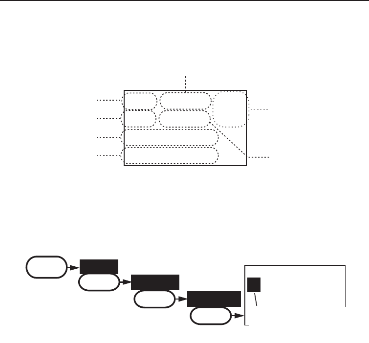
Installing the Hardware
When the GPS receiver is correctly connected, the display shows GPS Data
OK. If there is a problem with the GPS connection, the display shows Check
GPS. When the display shows GPS Data OK, press the SELECT button to
open the GPS status screen and see detailed GPS data:
16
06/20 11:00:00
208
o
30. 0 KT
35
o
40. 610 N
139
o
46. 564 E
Date
Time
Current
channel
Course
Latitude
Longitude Speed
Conguring the GPS
If the radio is receiving valid GPS data, it will automatically set the clock to
your local time based on the GPS location. You can adjust your local time
forward or back one hour if necessary (for example, if you are close to the
border of a time zone); you can also adjust for Daylight Savings Time.
Follow the steps below to adjust the time:
Display the menu and choose the 1. Setup sub-menu.
Select 2. GPS Setup and then choose Time Adjust.
The display shows your current local time. To adjust the time forward 3.
one hour, use the CHANNEL UP button. To adjust the time back one hour,
use the CHANNEL DOWN button. Press the SELECT button when you are
nished.
The display prompts you to conrm the setting: choose 4. Set to save the
new time or Cancel to exit time setup without saving. The radio returns
to the GPS Setup menu.
If your local area observes Daylight Savings Time, highlight5. Daylight
Save and press the SELECT button.
16
09 : 14
Time Adjust
Use the up or down
arrows to adjust the
time by one hour.
MENU Setup
SELECT
GPS Setup
SELECT
Time Adjust
SELECT
UM425 VHF OM.indd 47 28/9/11 11:55:22 AM

Installing the Hardware
48
Connecting to a charplotter
The UM425 provides a standard NMEA0183 GPS output that you can
connect to a chartplotter. When it receives another boat’s position data in a
DSC call, the radio sends the position data to the chartplotter so you can see
the location:
If Daylight Savings Time is currently in effect, select6. On. If Daylight
Savings Time is not currently in effect, select Off.
Press the 7. SELECT button. The radio activates the new time setting and
returns to the GPS Setup menu.
Disconnect the 1. accessory cable from the accessory connection on the
radio.
Connect the ORANGE wire of the 2. accessory cable to the NEGATIVE
(-) wire of your chartplotter’s NMEA data INPUT.
Connect the YELLOW wire of the 3. accessory cable to the POSITIVE
(+) wire of your chartplotter’s NMEA data INPUT
Be certain all wire connections are secure and that all open wires are 4.
adequately covered.
If you are nished connecting all external accessories, line up the 5.
arrows on the side of the accessory cable and connector and connect
the accessory cable to the accessory connector on the back of the
UM425.
NOTE: To extend the life of the radio, use waterproof tape to seal
electrical connections.
Connecting to an external speaker
You can use an external speaker to monitor the radio from a different part of
your boat or in a noisy environment. If you adjust the VOLUME-PWR knob on
the radio, it will also adjust the external speaker volume.
The UM425 supports an external speaker with the following specications:
• Minimum impedance of 4 Ohms
• Minimum power handling of 10 Watts
UM425 VHF OM.indd 48 28/9/11 11:55:22 AM

49
Installing the Hardware
Disconnect the 1. accessory cable from the accessory connection on
the radio.
Connect the BLACK wire of the 2. accessory cable to the GROUND
WIRE of your external speaker.
Connect the RED wire of the 3. accessory cable to the POSITIVE (+)
WIRE of your external speaker.
Be certain all wire connections are secure and that all open wires are 4.
adequately covered.
If you are nished connecting all external accessories, line up the 5.
arrows on the side of the accessory cable and connector and connect
the accessory cable to the accessory connector on the back of the
UM425.
NOTE: To extend the life of the radio, use waterproof tape to seal
electrical connections.
Connecting to an external PA speaker
If you connect the radio to a PA speaker, you can use the PA feature to make
announcements to other boats and people nearby.
The UM425 supports an external PA speaker with the following specications:
• Minimum impedance of 4 Ohms
• Minimum power handling of 10 Watts
1. Disconnect the accessory cable from the accessory connection on the
radio.
2. Connect the BLUE wire of the accessory cable to the GROUND
WIRE of your PA system.
3. Connect the BROWN wire of the accessory cable to the POSITIVE
(+) WIRE of your PA system.
4. Be certain all wire connections are secure and that all open wires are
adequately covered.
5. If you are nished connecting all external accessories, line up the
arrows on the side of the accessory cable and connector and connect
the accessory cable to the accessory connector on the back of the
UM425.
NOTE: To extend the life of the radio, use waterproof tape to seal
electrical connections.
UM425 VHF OM.indd 49 28/9/11 11:55:22 AM

Installing the Hardware
50
Press and hold the microphone 2.
PUSH TO TALK button. Speak clearly
in your normal voice (you don’t have
to shout). Use the VOLUME-PWR knob
on your UM425 to adjust the volume of the PA speaker.
Release the 3. PUSH TO TALK button when you're nished talking.
To turn off the PA feature and return to the radio mode you were using, 4.
press and hold the MENU-PA button for two seconds again.
PA
Public Address
Mode Selected
Using the PA feature
Press and hold the 1. MENU-
PA button for two seconds
to activate the PA feature.
The display shows PA in the
upper right hand corner.
UM425 VHF OM.indd 50 28/9/11 11:55:22 AM

51
Maintenance and Troubleshooting
Maintenance and Troubleshooting
Due to its rugged design, the UM425 requires very little maintenance. Howev-
er, it is a precision electronic instrument, so you should follow a few precau-
tions:
If the antenna has been damaged, you should not transmit except in •
the case of an emergency. A defective antenna may cause damage to
your radio.
You should arrange for periodic performance checks with your Uniden •
dealer.
Common questions
Problem Things to Try
The radio won’t power on. Check the power connections.
Check the fuse.
Check the master battery switch and branch
circuit that connect to the radio.
The radio won’t transmit. Make sure you are not in scan mode.
Make sure you are not trying to transmit on a
receive-only channel (see the channels and
frequency tables starting on page 57).
Make sure you are transmitting at the correct
power level for this channel (see the channels and
frequency tables starting on page 57).
Make sure the duration of each transmission is
less than 5 minutes.
Noise comes out of the
speaker all the time
Adjust the squelch level; it is probably too low.
I can’t hear anything (no vol-
ume) from the speaker.
Adjust the squelch level; it is probably too high.
I can transmit, but no one can
hear me.
Check your UIC channel settings (see Setting the
UIC channel mode (USA/CAN/INT) on page 12).
I can’t read the display. Adjust the contrast and backlight brightness level
(see page 22)
The display is too bright at
night.
Adjust the backlight brightness level.
(see page 22)
I can’t see any words on the
display.
Reset the radio back to the default contrast level:
turn off the radio; hold the menu key and turn it
back on.
UM425 VHF OM.indd 51 28/9/11 11:55:22 AM

Maintenance and Troubleshooting
52
Problem Things to Try
I’m not getting any GPS data
on my display.
Make sure your GPS receiver is correctly
connected (see Connecting to a GPS receiver).
Make sure your GPS receiver is working properly.
Make sure that your GPS receiver supports the
NMEA parameters described in NMEA Operation
on page 63.
I can’t make Group DSC calls. Make sure the Group MMSI was entered
correctly.
Where can I nd my radio’s
serial number?
Look on the bottom side of the radio
The radio won’t let me enter
my User MMSI. What do I do?
Contact customer service by visiting the customer
support page on www.uniden.com.au or
www.uniden.co.nz.
UM425 VHF OM.indd 52 28/9/11 11:55:22 AM

53
Maintenance and Troubleshooting
Engine Noise Suppression
Interference from the noise generated by the electrical systems of engines
is sometimes a problem with radios. The UM425 has been designed to be
essentially impervious to ignition noise and alternator noise. However, in
some installations it may be necessary to take measures to further reduce the
effect of noise interference. The UM425 radio DC battery wires, antenna lead,
and accessory cables should be routed away from the engine and engine
compartment, and from power cabling carrying high currents. In severe cases
of noise interference, it may be necessary to install a noise suppression kit.
Contact the dealer where you purchased the radio for more information.
UM425 VHF OM.indd 53 28/9/11 11:55:22 AM
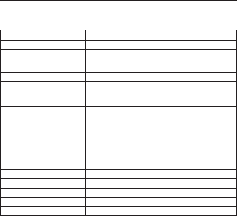
Specifications
54
Table 9 - Radio specications
(All specications are subject to change without notice.)
General
Controls VO L U M E -PW R , Squelch
Status Indicators Transmit power, Scan mode, Triple Watch mode, Battery
High, Battery low, USA, CAN, INT, Memory, GPS status
and Channel Display
Display LCD (Full Dot Matrix)
Buttons 16/9-Tri, Scan-Mem, Channel Up, Channel Down, Menu-
PA, Select, 1/25W, and Distress.
Connectors Antenna, accessory, and DC power
Size H 66.6 mm x W 162.6 mm x L 128 mm (without Heat Sink)
H 2.62 inches x W 6.40 inches x L 5.04 inches (without
Heat Sink)
Weight 0.93kg (2.05 pounds)
Supply Voltage Nominal 13.8V DC, negative ground (10.8 VDC to 15.6
VDC)
Standard Accessories Mounting bracket and hardware, DC power cable,
microphone hanger, spare fuse, accessory cable
Antenna Impedance 50 Ω nominal
Microphone Rugged 2 kΩ condenser mic element with coiled cord
Speaker 45 mm (1.77 inch), 8 Ω
Operating Temperature Range –15 °C to + 55 °C (+5 °F to +131 °F)
Shock and Vibration Meets or exceeds EIA standards, RS152B and RS204C
Specications
UM425 VHF OM.indd 54 28/9/11 11:55:22 AM

55
Specifications
Transmitter
Power Output 1 watt or 25 watt (user selectable)
Power Requirement 25 watts output: 6A@13.8V DC
Modulation ±5 kHz deviation
Hum and Noise Signal-to-Noise 45 dB with 3 kHz deviation with 1000 Hz modulating
frequency (nominal)
Audio Distortion Less than 8% with 3 kHz deviation with 1000 Hz
modulating frequency
Spurious Suppression -45 dBm @ Hi, -55 dBm @ Lo
Output Power Stabilization Built-in automatic level control (ALC)
Frequency Range 156 to 158 MHz
Frequency Stability ±1.5kHz @ –15°C to + 55°C
Receiver
Frequency Range 156 to 162 MHz
Sensitivity 0.25 μV for 12 dB SINAD
Circuit Dual Conversion Super Heterodyne PLL (Crystal for DSC)
Squelch Sensitivity 0.2 μV Threshold
Spurious Response 75 dB
Adjacent Channel Selectivity 78 dB @ ±25 kHz
Audio Output Power 2.5 watts (10% Distortion, 8 Ω load)
Power Requirement 400 mA @ 13.8V DC at squelched, 1000 mA @ 13.8V DC
at maximum audio output
IF Frequencies 1st 41.925 MHz, 2nd 455 kHz (1st 21.7 MHz, 2nd 455 kHz
for DSC)
UM425 VHF OM.indd 55 28/9/11 11:55:22 AM

Specifications
56
UM425 VHF OM.indd 56 28/9/11 11:55:22 AM

57
Specifications
Table 10 - International Channel Frequencies and Channel Tag
Ch No. RX Freq TX Freq Status Full Name
1 160.6500 156.0500 Duplex Marine operator
2 160.7000 156.1000 Duplex Marine operator
3 160.7500 156.1500 Duplex Marine operator
4 160.8000 156.2000 Duplex Marine operator
5 160.8500 156.2500 Duplex Marine operator
6 156.3000 156.3000 Simplex Inter-ship safety
7 160.9500 156.3500 Duplex Marine operator
8 156.4000 156.4000 Simplex Commercial (ship-ship)
9 156.4500 156.4500 Simplex Boater calling channel
10 156.5000 156.5000 Simplex Commercial
11 156.5500 156.5500 Simplex Vessel trafc system
12 156.6000 156.6000 Simplex Vessel trafc system
13 156.6500 156.6500 Simplex Bridge to bridge
14 156.7000 156.7000 Simplex Vessel trafc system
15 156.7500 156.7500 Simplex, 1W Environmental
16 156.8000 156.8000 Simplex Distress, Safety, Calling
17 156.8500 156.8500 Simplex, 1W Govt maritime control
18 161.5000 156.9000 Duplex Port operation
19 161.5500 156.9500 Duplex Commercial
20 161.6000 157.0000 Duplex Port operation
21 161.6500 157.0500 Duplex Port operation
22 161.7000 157.1000 Duplex Port operation
23 161.7500 157.1500 Duplex Marine operator
24 161.8000 157.2000 Duplex Marine operator
25 161.8500 157.2500 Duplex Marine operator
26 161.9000 157.3000 Duplex Marine operator
27 161.9500 157.3500 Duplex Marine operator
28 162.0000 157.4000 Duplex Marine operator
60 160.6250 156.0250 Duplex Marine operator
61 160.6750 156.0750 Duplex Marine operator
62 160.7250 156.1250 Duplex Marine operator
63 160.7750 156.1750 Duplex Marine operator
64 160.8250 156.2250 Duplex Marine operator
65 160.8750 156.2750 Duplex Marine operator
66 160.9250 156.3250 Duplex Marine operator
67 156.3750 156.3750 Simplex Bridge to bridge
68 156.4250 156.4250 Simplex Non commercial
69 156.4750 156.4750 Simplex Non commercial
70 ( 156.5250 156.5250 ) DSC Only DSC
Channel and frequencies
UM425 VHF OM.indd 57 28/9/11 11:55:23 AM
Specifications
58
Ch No. RX Freq TX Freq Status Full Name
71 156.5750 156.5750 Simplex Non commercial
72 156.6250 156.6250 Simplex Non commercial
73 156.6750 156.6750 Simplex Port operation
74 156.7250 156.7250 Simplex Port operation
75 156.7750 156.7750 Simplex, 1W Port operation
76 156.8250 156.8250 Simplex, 1W Port operation
77 156.8750 156.8750 Simplex Port operation (ship-ship)
78 161.5250 156.9250 Duplex Port operation
79 161.5750 156.9750 Duplex Port operation
80 161.6250 157.0250 Duplex Port operation
81 161.6750 157.0750 Duplex Port operation
82 161.7250 157.1250 Duplex Port operation
83 161.7750 157.1750 Duplex Port operation
84 161.8250 157.2250 Duplex Marine operator
85 161.8750 157.2750 Duplex Marine operator
86 161.9250 157.3250 Duplex Marine operator
87 157.3750 157.3750 Simplex Marine operator
88 157.4250 157.4250 Simplex Marine operator
Table 10 - International Channel Frequencies and Channel Tag
(cont'd)
UM425 VHF OM.indd 58 28/9/11 11:55:23 AM

59
Specifications
Table 11 - USA Channel Frequencies and Channel Tag
Ch No. RX Freq (MHz) TX Freq (MHz) Status Full Name
1 “A” 156.0500 156.0500 Simplex Vessel trafc system/
Commercial
5 “A” 156.2500 156.2500 Simplex Vessel trafc system /
Commercial
6 156.3000 156.3000 Simplex Inter-ship safety
7 “A” 156.3500 156.3500 Simplex Commercial
8 156.4000 156.4000 Simplex Commercial
9 156.4500 156.4500 Simplex Non commercial
10 156.5000 156.5000 Simplex Commercial
11 156.5500 156.5500 Simplex Vessel trafc system
12 156.6000 156.6000 Simplex Vessel trafc system
13 156.6500 156.6500 Simplex, 1W Bridge to bridge
14 156.7000 156.7000 Simplex Vessel trafc system
15 156.7500 Inhibit Receive Only Environmental
16 156.8000 156.8000 Simplex Distress, Safety, Calling
17 156.8500 156.8500 Simplex, 1W Govt maritime control
18 “A” 156.9000 156.9000 Simplex Commercial
19 “A” 156.9500 156.9500 Simplex Commercial
20 161.6000 157.0000 Duplex Port operation
20 “A” 157.0000 157.0000 Simplex Port operation
21 “A” 157.0500 157.0500 Simplex Coast guard only
22 “A” 157.1000 157.1000 Simplex Coast guard
23 “A” 157.1500 157.1500 Simplex Coast guard only
24 161.8000 157.2000 Duplex Marine operator
25 161.8500 157.2500 Duplex Marine operator
26 161.9000 157.3000 Duplex Marine operator
27 161.9500 157.3500 Duplex Marine operator
28 162.0000 157.4000 Duplex Marine operator
63 “A” 156.1750 156.1750 Simplex Vessel trafc system
65 “A” 156.2750 156.2750 Simplex Port operation
66 “A” 156.3250 156.3250 Simplex Port operation
67 156.3750 156.3750 Simplex, 1W Bridge to bridge
68 156.4250 156.4250 Simplex Non commercial
69 156.4750 156.4750 Simplex Non commercial
70 ( 156.5250 156.5250 ) DSC Only DSC
71 156.5750 156.5750 Simplex Non commercial
72 156.6250 156.6250 Simplex Non commercial (ship-ship)
73 156.6750 156.6750 Simplex Port operation
74 156.7250 156.7250 Simplex Port operation
75 156.775 156.7750 Simplex, 1W Port operation
UM425 VHF OM.indd 59 28/9/11 11:55:23 AM

Specifications
60
Table 11 - USA Channel Frequencies and Channel Tag (cont'd)
The "A" indicates simplex use of the ship station transmit side of an international duplex channel, and that operations are different from that of
international operations on that channel.
Ch No. RX Freq (MHz) TX Freq (MHz) Status Full Name
76 156.825 156.8250 Simplex, 1W Port operation
77 156.8750 156.8750 Simplex, 1W Port operation (ship-ship)
78 “A” 156.9250 156.9250 Simplex Non commercial
79 “A” 156.9750 156.9750 Simplex Commercial
80 “A” 157.0250 157.0250 Simplex Commercial
81 “A” 157.0750 157.0750 Simplex Government
82 “A” 157.1250 157.1250 Simplex Government
83 “A” 157.1750 157.1750 Simplex Coast guard
84 161.8250 157.2250 Duplex Marine operator
85 161.8750 157.2750 Duplex Marine operator
86 161.9250 157.3250 Duplex Marine operator
87 157.3750 157.3750 Simplex Marine operator
88 157.4250 157.4250 Simplex Commercial (ship-ship)
UM425 VHF OM.indd 60 28/9/11 11:55:23 AM

61
Specifications
Table 12 - Canadian Channel Frequencies and Channel Tag
Ch No. RX Freq TX Freq Status Full Name
1 160.6500 156.0500 Duplex Marine operator
2 160.7000 156.1000 Duplex Marine operator
3 160.7500 156.1500 Duplex Marine operator
4 “A” 156.2000 156.2000 Simplex Canadian coast guard
5 “A” 156.2500 156.2500 Simplex Vessel trafc system
6 156.3000 156.3000 Simplex Inter-ship safety
7 “A” 156.3500 156.3500 Simplex Commercial
8 156.4000 156.4000 Simplex Commercial
9 156.4500 156.4500 Simplex Boater calling channel
10 156.5000 156.5000 Simplex Commercial
11 156.5500 156.5500 Simplex Vessel trafc system
12 156.6000 156.6000 Simplex Vessel trafc system
13 156.6500 156.6500 Simplex, 1W Bridge to bridge
14 156.7000 156.7000 Simplex Vessel trafc system
15 156.7500 156.7500 Simplex Environmental
16 156.8000 156.8000 Simplex Distress, Safety, Calling
17 156.8500 156.8500 Simplex, 1W State control
18 “A” 156.9000 156.9000 Simplex Commercial
19 “A” 156.9500 156.9500 Simplex Canadian coast guard
20 161.6000 157.0000 Duplex, 1W Port operation
21 “A” 157.0500 157.0500 Simplex Canadian coast guard
22 “A” 157.1000 157.1000 Simplex Canadian coast guard
23 161.7500 157.1500 Duplex Marine operator
24 161.8000 157.2000 Duplex Marine operator
25 161.8500 157.2500 Duplex Marine operator
26 161.9000 157.3000 Duplex Marine operator
27 161.9500 157.3500 Duplex Marine operator
28 162.0000 157.4000 Duplex Marine operator
60 160.6250 156.0250 Duplex Marine operator
61 “A” 156.0750 156.0750 Simplex Canadian coast guard
62 “A” 156.1250 156.1250 Simplex Canadian coast guard
63 "A" 156.1750 156.1750 Simplex Port operation
64 160.8250 156.2250 Duplex Marine operator
64 “A” 156.2250 156.2250 Simplex Port operation
65 “A” 156.2750 156.2750 Simplex Port operation
66 “A” 156.3250 156.3250 Simplex, 1W Port operation
67 156.3750 156.3750 Simplex Bridge to bridge
68 156.4250 156.4250 Simplex Non commercial
69 156.4750 156.4750 Simplex Non commercial
70 ( 156.5250 156.5250 ) DSC Only DSC
UM425 VHF OM.indd 61 28/9/11 11:55:23 AM

Specifications
62
Ch No. RX Freq TX Freq Status Full Name
71 156.5750 156.5750 Simplex Non commercial
72 156.6250 156.6250 Simplex Non commercial
73 156.6750 156.6750 Simplex Port operation
74 156.7250 156.7250 Simplex Port operation
75 156.7750 156.7750 Simplex, 1W Port operation
76 156.8250 156.8250 Simplex, 1W Port operation
77 156.8750 156.8750 Simplex, 1W Port operation
78 “A” 156.9250 156.9250 Simplex Inter ship
79 “A” 156.9750 156.9750 Simplex Inter ship
80 “A” 157.0250 157.0250 Simplex Inter ship
81 “A” 157.0750 157.0750 Simplex Canadian coast guard
82 “A” 157.1250 157.1250 Simplex Canadian coast guard
83 161.7750 157.1750 Duplex Canadian coast guard
83 “A” 157.1750 157.1750 Simplex Canadian coast guard
84 161.8250 157.2250 Duplex Marine operator
85 161.8750 157.2750 Duplex Marine operator
86 161.9250 157.3250 Duplex Marine operator
87 157.3750 157.3750 Simplex Port operation
88 157.4250 157.4250 Simplex Port operation
Table 12 - Canadian Channel Frequencies and Channel Tag (cont'd)
The "A" indicates simplex use of the ship station transmit side of an international duplex channel, and that operations are different from that of
international operations on that channel.
UM425 VHF OM.indd 62 28/9/11 11:55:23 AM

63
Specifications
NMEA Operation
This radio supports NMEA0183 version 3.01.
NMEA Input
If you have difculty getting the UM425 to receive data from your GPS receiver,
check the device’s conguration. It should be set to the parameters shown in the
table below.
Table 13 - NMEA Input Parameters
Baud rate 4800 bps
Data bits 8
Parity None
Stop bits 1
Data amplitude Over 3.0 V
Drive capability Over 10 mA
The radio supports RMC, GLL, GNS,
GGA and ZDA sentences. When
these sentences are received, the
radio displays latitude/longitude,
date, time, course, and speed. If
any sentence except an RMC or
GLL sentence is received, the radio
uses the information based on the
following priority order.
• Status:RMC > GLL > GNS > GGA
• Latitude/Longitude:RMC > GLL > GNS > GGA
• UTC Time: RMC > GLL > GNS > GGA > ZDA
• Date: RMC > ZDA
• Speed / Course:RMC
NOTES :
• If the radio receives only a GLL sentence, the radio does not display the
current speed, course, and date.
• If the radio receives both RMC and GLL sentences, the radio uses only
the RMC sentence.
• Status data is used to check whether the GPS data is valid or invalid.
NMEA Output
When the radio receives a DSC call (Distress, Position Reply, or Position
Send), it outputs a DSC/DSE sentence from the NMEA output port.
NOTE: When the radio receives a distress call, it outputs a sentence in the
following format.
• $CDDSC,12,3081234000,,07,00,0354013946,0657,,,S,E*6D
• $CDDSE,1,1,A,3081234000,00,60875646*13
Table 12 - Canadian Channel Frequencies and Channel Tag (cont'd)
UM425 VHF OM.indd 63 28/9/11 11:55:23 AM

Regulations and Safety Warnings
64
Regulations and Safety Warnings
Basic radio guidelines
You should familiarize yourself with the rules on marine radios and be aware
of which rules apply to your boat.
DSC: Frequently Asked Questions
The following information is sourced from the Australian Maritime Safety Authority's
DSC FAQ.
What is the status of VHF DSC coverage in Australia?
In Australian waters, VHF DSC is for ship-to-ship alerting. There is no ofcial
shore-based infrastructure but there are a number of volunteer marine rescue
(VMR) stations that have installed VHF DSC and a check with your local
VMR should be made.
VHF DSC for small craft is primarily for distress, urgency and safety
purposes.
How should VHF DSC be used?
In Australian waters, Channel 70 should be used for DSC distress alerts only.
Once an alert has been sent the party in distress should monitor Channel
16, the distress and calling channel. Parties receiving the DSC distress alert
should switch to Channel 16 and acknowledge the MAYDAY call by voice
giving their identity and signalling “Received MAYDAY”. If the party in distress
does not receive an acknowledgement to their DCS alert they should transmit
the standard MAYDAY call by voice on Channel 16. There are still quite a
number of boats that do not carry DSC radios.
Because Channel 16 is the distress and calling frequency it should only be
used for general trafc to raise another party. Once contact has been made,
all routine trafc should be passed on another agreed VHF channel.
Is a call sign or Maritime Mobile Service Identity (MMSI)
needed?
An MMSI is a unique nine-digit code set into your DSC terminal to identify
your vessel. You need only one of these if you have multiple DSC radios. You
use the same MMSI for all radios on board the one vessel as it is a ship’s
identity. Because VHF radios now operate under a Class License there is
no requirement for an ofcial call sign but an operator must have a Maritime
Radio Operators Certicate of Prociency (MROCP).
UM425 VHF OM.indd 64 28/9/11 11:55:23 AM

65
Regulations and Safety Warnings
How can a MMSI be applied for?
The Australian Maritime Safety Authority allocates MMSI. To apply for an
MMSI complete the MMSI Application form available for download via
www.amsa.gov.au/mmsi. This page has important information about MMSI
and DSC radio.
What qualications are needed to operate a VHF DSC radio?
The minimum qualication to operate a VHF radio with or without DSC is a
Marine Radio Operator’s VHF Certicate of Prociency (MROVCP). VHF
radios are covered by a Class License so an individual station license is no
longer required.
The Marine Radio Operator’s Handbook produced by the Australian Maritime
College provides further information about qualications, licensing and DSC
operations. It is available at www.amcom.amc.edu.au
Antenna Selection and Installation
Your UM425 has been designed to accommodate all of the popular marine VHF
antennas. However, the selection and the proper installation of the antenna is the
responsibility of the user or installer.
The antenna used with this radio should be installed using the following guidelines to
ensure a safe distance between the antenna and persons close by.
Small whip antennas (3 dB) or smaller should be installed with at least 1m away •
from any area where people are likely to be.
Larger antennas (6 dB or 9 dB) should be installed with at least 2m away.•
While the radio is transmitting, do not come closer to the antenna than the •
recommended safe distance.
Do not touch the antenna when the radio is powered on and might begin •
transmitting.
UM425 VHF OM.indd 65 28/9/11 11:55:23 AM

Two Year Limited Warranty
66
UNIDEN UM425 VHF
IMPORTANT Satisfactory evidence of the original purchase is required for warranty service
Please refer to our Uniden website for any details or warranty durations offered in addition to those
contained below.
Warrantor
The warrantor is either Uniden Australia Pty Limited ABN 58 001 865 498 (“Uniden Aust”) or Uniden New
Zealand Limited (“Uniden NZ”) as the case may be.
Terms of Warranty
Uniden Aust/NZ warrants to the original retail purchaser only that the UM425 VHF (“the Product”), will be
free from defects in materials and craftsmanship for the duration of the warranty period, subject to the
limitations and exclusions set out below.
Warranty Period
This warranty to the original retail purchaser is only valid in the original country of purchase for a Product
first purchased either in Australia or New Zealand and will expire two (2) years from the date of the original
retail sale.
If a warranty claim is made, this warranty will not apply if the Product is found by Uniden to be:
(A) Damaged or not maintained in a reasonable manner or as recommended in the relevant Uniden
Owner’s Manual;
(B) Modified, altered or used as part of any conversion kits, subassemblies or any configurations not sold
by Uniden Aust or Uniden NZ;
(C) Improperly installed contrary to instructions contained in the relevant Owner’s Manual
(D) Repaired by someone other than an authorized Uniden Repair Agent in relation to a defect or
malfunction covered by this warranty; or
(E) Used in conjunction with any equipment, parts or a system not manufactured by Uniden.
Parts Covered
This warranty covers the Product and included accessories.
User-generated Data
This warranty does not cover any claimed loss of or damage to user-generated data (including but without
limitation phone numbers, addresses and images) that may be stored on your Product.
Statement of Remedy
If the Product is found not to conform to this warranty as stated above, the Warrantor, at its discretion,
will either repair the defect or replace the Product without any charge for parts or service. This warranty
does not include any reimbursement or payment of any consequential damages claimed to arise from a
Product’s failure to comply with the warranty.
Our goods come with guarantees that cannot be excluded under the Australian Consumer Law. You are
entitled to a replacement or refund for a major failure and for compensation for any other reasonably
foreseeable loss or damage. You are also entitled to have the goods repaired or replaced if the goods fail
to be of acceptable quality and the failure does not amount to a major failure.
This warranty is in addition to and sits alongside your rights under either the COMPETITION AND
CONSUMER ACT 2010 (Australia) or the CONSUMER GUARANTEES ACT (New Zealand) as the case
may be, none of which can be excluded.
Procedure for Obtaining Warranty Service
Depending on the country in which the Product was first purchased, if you believe that your Product does
not conform with this warranty, you should deliver the Product, together with satisfactory evidence of your
original purchase (such as a legible copy of the sales docket) to Uniden at the addresses shown below.
You should contact Uniden regarding any compensation that may be payable for your expenses incurred
in making a warranty claim. Prior to delivery, we recommend that you make a backup copy of any phone
numbers, images or other data stored on your Product, in case it is lost or damaged during warranty
service.
UNIDEN AUSTRALIA PTY LTD
Service Division
345 Princes Highway,
Rockdale, NSW 2216
Phone number: 1300 366 895
Email address: custservice@uniden.com.au
UNIDEN NEW ZEALAND LTD
Service Division
150 Harris Road, East Tamaki
Auckland 2013
Phone number: (09) 273 8377
Email address: service@uniden.co.nz
UM425 VHF OM.indd 66 28/9/11 11:55:23 AM
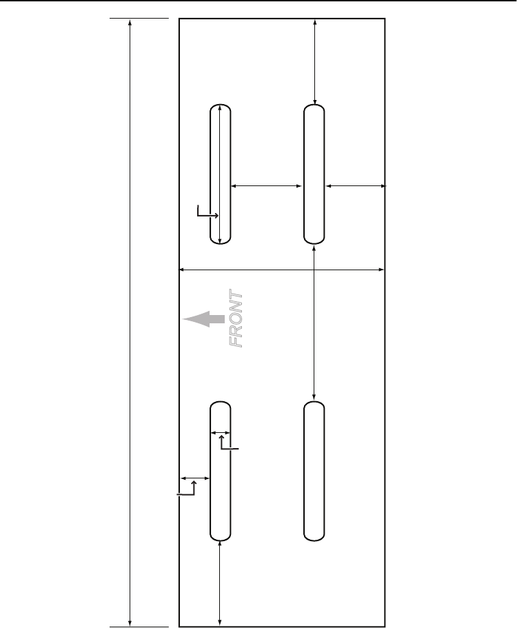
67
Mounting Bracket Template
22 mm/
0.87 in (7/8)
156 mm/
6.14 in (6 5/32)
5.5 mm/
0.2 in
(7/32)
18.5 mm/
0.73 in (3/4)
22 mm/
0.87 in (7/8)
36 mm/1.42 in (1 7/16)
40 mm/
1.6 in (1 9/16)
15.5 mm/
0.61 in
(5/8)
53 mm/
2.1 in (2 3/32)
8 mm
/0.31 in
(5/16)
UM425 VHF OM.indd 67 28/9/11 11:55:24 AM

© 2011 Uniden Australia Pty Limited/Uniden New Zealand Limited
Printed in PRC UTZZ01627ZA(0)
UM425 VHF OM.indd 68 28/9/11 11:55:24 AM
