User Manual

3,13DG
3URJUDPPHU¶V0DQXDO
3HUVRQDO,'1XPEHU3DG
:LWK(09/HYHO7UDQVDFWLRQ&DSDELOLWLHV
3&,326$6SHFLILFDWLRQ
308
5HYLVLRQ

PIN Pad 791 Programmer’s Manual (PCI POS-A) UDN PM0103-U Rev. 06
Notice, Agency Approved, and Warranty 2015-04-20
Page 2
Uniform Industrial Corp. Proprietary and Confidential Total 342 pages
NOTICE
The issuer of this manual has made every effort to provide accurate information. The issuer will not be held
liable for any technical and editorial omission or errors made herein; nor for incidental consequential
damages resulting from the furnishing, performance or use of this material. This document contains
proprietary information that is protected by copyright. All rights are reserved. No part of this document may be
photocopied, reproduced, or translated without the prior written consent of the issuer. The information
provided in this manual is subject to change without notice.
第十二條 經型式認證合格之低功率射頻電機,非經許可,公司、商號或使用者均不得擅自變更頻率、 大功率
或變更原設計之特性及功能。
第十四條 低功率射頻電機之使用不得影響飛航安全及干擾合法通信;經發現有干擾現象時,應立即停用,並改
善至無干擾時方得繼續使用。
前項合法通信,指依電信法規定作業之無線電通信。低功率射頻電機須忍受合法通信或工業、科學及醫療用電
波輻射性電機設備之干擾。
AGENCY APPROVED
- FCC class B
- CE class B
WARRANTY
This product is served under one-year warranty to the original purchaser. Within the warranty period,
merchandise found to be defective would be repaired or replaced. This warranty applies to the products only
under the normal use of the original purchaser, and in no circumstances covers incidental or consequential
damages through consumers’ misuse or modification of the products.

PIN Pad 791 Programmer’s Manual (PCI POS-A) UDN PM0103-U Rev. 06
Notice, Agency Approved, and Warranty 2015-04-20
Page 3
Uniform Industrial Corp. Proprietary and Confidential Total 342 pages
Document History
Document Version
Apply to FW version
Change
01 PP791: 10A.01
SysMgr: 10A.01
First Release
02 PP791: 10A.03
SysMgr: 10A.03
Modify the description of I17 command.
Remove “All” type of saver screen setting in BB
command.
Add a error code in 71 command.
Add a error code in 91 command.
03 PP791: 10A.05
SysMgr: 10A.04
Add a error code in 02 command.
Add a error code in 91 command.
04 PP791: 10A.06
SysMgr: 10A.05
Add message JA for set boot logo.
EMV Level 2 transaction messages for PCD
implementation done.
05 PP791: 10A.06
SysMgr: 10A.05
Add Contactless EMV transaction description in EMV
Level 2 transaction messages.
Message T19, T23 update message flow.
Add PCD MiFare Message.
Split EMV transaction chapter into two, Contact and
Contactless EMV transaction.
Remove I10 command.
Add a new description of WIFI/BT setting menu.
06 PP791: 10A.09
SysMgr: 10A.08
Add NCC Compliance and Advisory Statement.

PIN Pad 791 Programmer’s Manual (PCI POS-A) UDN PM0103-U Rev. 06
Section 1 – Introduction 2015-04-20
Page4
Uniform Industrial Corp. Proprietary and Confidential Total 342 pages
Table of Contents
Section 1 Introduction _________________________________________________ 11
PIN Pad components _______________________________________________________________ 11
Display ________________________________________________________________ 12
Keypad ________________________________________________________________ 12
Communication Interface __________________________________________________ 12
Magnetic and Smart Card reader ____________________________________________ 12
Smart card and Security Access Module (SAM) interfaces ________________________ 13
Tamper Evidence and Tamper Responsive ____________________________________________ 13
Section 2 System Manager _____________________________________________ 14
Introduction 14
Security management ______________________________________________________________ 14
Main menu of system manager ______________________________________________________ 15
Prepare downloading ______________________________________________________________ 15
“Download” menu _________________________________________________________________ 16
“Date & Time” menu _______________________________________________________________ 17
“Setting” menu 17
“System Info” menu _______________________________________________________________ 18
“Self Test” menu __________________________________________________________________ 18
“Change Password” menu __________________________________________________________ 19
Section 3 PP791 Setup & Diagnostic Menu ________________________________ 20
Call up Diagnostic Menu ____________________________________________________________ 20
Diagnostic Menu 1: HW Tests _______________________________________________________ 20
Diagnostic Menu 2: Display Info _____________________________________________________ 21
Diagnostic Menu 3: Setup COM Port __________________________________________________ 21
Diagnostic Menu 4: Set LCD Backlight ________________________________________________ 22
Diagnostic Menu 5: Logo Setup ______________________________________________________ 23
Diagnostic Menu 6: Setup Password _________________________________________________ 23
Diagnostic Menu 7: Set Keypad Beep _________________________________________________ 23
About USB virtual COM port (only applied on USB version) ______________________________ 24
Call up Interface Setting Menu _______________________________________________________ 24
Interface Setting Menu 1: COMM. Interface Switch ______________________________________ 24
Interface Setting Menu 2: WIFI Setting ________________________________________________ 24
Interface Setting 3: Bluetooth Setting _________________________________________________ 25
Interface Setting Menu 4: Status _____________________________________________________ 25
Section 4 Message format ______________________________________________ 26
Notation Conventions ______________________________________________________________ 26
Control Codes ___________________________________________________________ 26
Message frame summary ___________________________________________________________ 27

PIN Pad 791 Programmer’s Manual (PCI POS-A) UDN PM0103-U Rev. 06
Section 1 – Introduction 2015-04-20
Page5
Uniform Industrial Corp. Proprietary and Confidential Total 342 pages
Message type ___________________________________________________________ 27
Time-out _______________________________________________________________ 27
Transmission Error _______________________________________________________ 27
Packet Error ____________________________________________________________ 27
Section 5 Administration and maintenance messages _______________________ 28
Message 02 Load Master Key ____________________________________________________ 28
Symmetric Keys Loading Authentication ______________________________________________ 32
Message 04 Check Master Key ____________________________________________________ 34
Message 05 Load Serial Number __________________________________________________ 36
Message 06 Get Serial Number ___________________________________________________ 37
Message 07 Test DES Implementation ______________________________________________ 38
Message 08 Select Master Key ____________________________________________________ 39
Message 09 Communication Test _________________________________________________ 40
Message 11 PIN Pad Device Connection Test _______________________________________ 42
Message 12 Select Prompt Language ______________________________________________ 43
Message 13 Adjust COM1 Baud Rate (RS-232 version only) ___________________________ 45
Message 14 Enable/Disable Timer Display __________________________________________ 47
Message 15 Adjust LCD Backlight Level ____________________________________________ 49
Message 16 Remote self-test request ______________________________________________ 50
Message 17 Request random number ______________________________________________ 51
Message 18 Set PIN pad system time ______________________________________________ 52
Message 19 Query Firmware Version ______________________________________________ 56
Message 1C Query Hardware Capability ___________________________________________ 58
Message 1F Query Usable Prompt Table ____________________________________________ 59
Message 1J Turn ON/OFF LCD Backlight ___________________________________________ 61
Message 1K Turn ON/OFF LCD Power-save mode ____________________________________ 63
Message 1M Setup Keypad Beeper _________________________________________________ 65
Section 6 Contact EMV Level 2 transaction messages ________________________ 67
Message T01 Terminal Configuration Setup _________________________________________ 69
Message T02 Terminal Configuration Setup Response ________________________________ 72
Message T03 Certification Authority Public Key Setup ________________________________ 73
Message T04 Certification Authority Public Key Setup Response _______________________ 75
Message T05 EMV Application Configuration Setup __________________________________ 76
Message T06 EMV Application Configuration Setup Response _________________________ 80
Message T07 Data Format Table Setup _____________________________________________ 81
Message T08 Data Format Table Setup Response ____________________________________ 83
Message T09 EMV Config Data Query Message ______________________________________ 84
Message T0A Response of EMV Config Data Query Message _____________________________ 85
Message T0B Delete EMV Configuration Data Message. _________________________________ 86
Message T0C Response of Delete EMV Configuration Data Message. ______________________ 87

PIN Pad 791 Programmer’s Manual (PCI POS-A) UDN PM0103-U Rev. 06
Section 1 – Introduction 2015-04-20
Page6
Uniform Industrial Corp. Proprietary and Confidential Total 342 pages
Message T11 Application Select ___________________________________________________ 88
Message T12 Application Select Response _________________________________________ 89
Message T13 Application Select Next ______________________________________________ 90
Message T15 Start Transaction ____________________________________________________ 91
Message T16 Start Transaction Response __________________________________________ 93
Message T17 Send Online Authorized Code _________________________________________ 95
Message T19 Send Issuer Script Command _________________________________________ 97
Message T1D Transaction Data loading _______________________________________________ 99
Message T1E Transaction Data loading Response ____________________________________ 101
Message T20 Send Issuer Script Command Response _______________________________ 102
Message T21 Get Transaction Result’s Data ________________________________________ 103
Message T22 Get Transaction Result’s Data Response _______________________________ 104
Message T23 Erase EMV Transaction Log. _________________________________________ 105
Message T1C Terminal Cancel Transaction ___________________________________________ 106
Message T25 Get Batch Data ____________________________________________________ 107
Message T26 Response of Get Batch Data message _________________________________ 109
Message T27 Get Online authorization Data ________________________________________ 110
Message T28 Response of Get Online authorization Data message ____________________ 111
Message T29 Get Reversal Data __________________________________________________ 112
Message T2A Response of Get Reversal Data message _________________________________ 113
Overall Contact EMV Level 2 transaction flow reference ________________________________ 114
Ref. 1 Packet command flow for transaction with offline ____________________ 114
Ref. 2 Packet command flow for transaction with online _____________________ 114
Ref. 3 Packet command flow for transaction with MSR. _____________________ 115
Ref. 4 Packet command flow for transaction with online and Issuer Script command
Processing 116
Ref. 5 Packet command flow for first EMV application is blocked _____________ 116
Section 7 Contactless EMV Level 2 transaction messages __________________ 118
Message T51 PCD Terminal Configuration Setup _____________________________________ 120
Message T52 PCD Terminal Configuration Setup Response _____________________________ 123
Message T53 PCD Certification Authority Public Key Setup _____________________________ 124
Message T54 PCD Certification Authority Public Key Setup Response ____________________ 126
Message T55 PCD Application Configuration Setup ____________________________________ 127
Message T56 PCD Application Configuration Setup Response ___________________________ 131
Message T59 PCD Config Data Query Message________________________________________ 132
Message T5A Response of PCD Config Data Query Message ____________________________ 133
Message T5B Delete PCD Configuration Data Message. ________________________________ 134
Message T5C Response of Delete PCD Configuration Data Message. _____________________ 135
Message T5D PCD House Keeping Message. _________________________________________ 136
Message T5E Response of PCD House Keeping Message. ______________________________ 137

PIN Pad 791 Programmer’s Manual (PCI POS-A) UDN PM0103-U Rev. 06
Section 1 – Introduction 2015-04-20
Page7
Uniform Industrial Corp. Proprietary and Confidential Total 342 pages
Message T61 Start Transaction _____________________________________________________ 138
Message T62 Start Transaction Response ____________________________________________ 140
Message T63 Get Transaction Result’s Data __________________________________________ 141
Message T64 Get Transaction Result’s Data Response _________________________________ 142
Message T65 Get Online authorization Data __________________________________________ 143
Message T66 Response of Get Online authorization Data message _______________________ 144
Message T6C Cancel PCD Transaction _______________________________________________ 145
Message T71 Send PCD Online Authorized Code ______________________________________ 146
Message T73 Send Issuer Script Command ________________________________________ 148
Message T75 Revocation List Setup _________________________________________________ 149
Message T76 Revocation List Setup Response ________________________________________ 150
Message T77 Exception List Setup __________________________________________________ 151
Message T78 Exception List Setup Response _________________________________________ 152
Overall Contactless EMV Level 2 transaction flow reference _____________________________ 153
Ref. 1 Packet command flow for transaction with offline approval _____________ 153
Ref. 2 Packet command flow for transaction with online approval _____________ 154
Section 8 MIFARE card messages ______________________________________ 155
Message P01 Enable/Disable MIFARE _____________________________________________ 156
Message P02 Query MIFARE Presence ____________________________________________ 158
Message P03 MIFARE Anti-collision _______________________________________________ 160
Message P04 MIFARE Selection __________________________________________________ 162
Message P05 MIFARE Classic/Ultralight Card Activation _____________________________ 164
Message P06 MIFARE Classic/Ultralight Card HALT _________________________________ 166
Message P07 MIFARE Classic Card Authentication ___________________________________ 168
Message P08 MIFARE Ultralight Card Read Page ____________________________________ 170
Message P09 MIFARE Ultralight Card Write Page _____________________________________ 172
Message P10 MIFARE Classic/Ultralight Card Read Block ____________________________ 174
Message P11 MIFARE Classic/Ultralight Card Write Block _____________________________ 176
Message P12 MIFARE Classic/Ultralight Card Read Sector ____________________________ 178
Message P13 MIFARE Classic/Ultralight Card Write Sector ___________________________ 180
Message P14 MIFARE Classic Card Value Operation __________________________________ 182
Message P15 Load MIFARE key __________________________________________________ 184
Message P16 Identify MIFARE Card Type ___________________________________________ 186
Message P17 MIFARE DESfire Card Activation ______________________________________ 188
Message P18 MIFARE DESfire Card Deselect ________________________________________ 190
Message P19 I/O to MIFARE card with APDU format _________________________________ 192
Message P20 I/O to MIFARE card for block data exchange _____________________________ 194
Overall MIFARE operation flow reference _____________________________________________ 196
Ref. 1 Activate and authenticate for MIFARE classic card. ___________________ 196
Ref. 2 The quick method for activating classic card. ________________________ 197

PIN Pad 791 Programmer’s Manual (PCI POS-A) UDN PM0103-U Rev. 06
Section 1 – Introduction 2015-04-20
Page8
Uniform Industrial Corp. Proprietary and Confidential Total 342 pages
Ref. 3 Activate and authenticate for MIFARE Ultralight card. ________________ 198
Ref. 4 The quick method for activating Ultralight card. ______________________ 199
Ref. 5 Activating for DESFire card _____________________________________ 200
Section 9 Online transaction messages with Master/Session Keys (MK/SK) ____ 201
Message 70 PIN entry request (MK/SK) ____________________________________________ 201
Message 71 Encrypted PIN Block Response _______________________________________ 204
Message 72 PIN Entry Cancel ____________________________________________________ 206
Message Z0 Move Display Cursor ________________________________________________ 207
Message Z1 Reset State ________________________________________________________ 208
Message Z2 Display String ______________________________________________________ 209
Message Z3 Display Line Prompts ________________________________________________ 212
Z2 / Z3 Authenticated mode with fixed prompt ________________________________________ 215
Z2 / Z3 PIN entry mode with fixed prompt_____________________________________________ 215
Message Z2 Display String with Authentication Code ________________________________ 216
Message Z3 Display Line Prompts with Authentication Code _________________________ 218
Example to use Z2 / Z3 with Authencation Code. ______________________________________ 220
Message Z42 Read Key Code ____________________________________________________ 221
Message Z43 Read Key Code Response ___________________________________________ 222
Message Z50 String Entry Request _______________________________________________ 223
Message Z51 String Entry Response ______________________________________________ 225
Message Z60 PIN entry request with external prompt (MK/SK) ________________________ 226
Message Z62 PIN entry request with customized prompt (MK/SK) _____________________ 228
Message Z66 Message Authentication Code (MAC) Request __________________________ 231
Message Z67 Message Authentication Code (MAC) Response_________________________ 234
Message Z7 Turn ON/OFF CANCEL Message Display ________________________________ 236
Message Z8 Set Idle Prompt _____________________________________________________ 237
Section 10 Online transaction messages with Derived Unique Key per Transaction
(DUKPT) _____________________________________________________________ 238
Message 60 Pre-authorization PIN Entry Request ___________________________________ 239
Message 62 Pre-authorization Amount Authorization Request ________________________ 241
Message 63 Pre-authorization Amount Authorization Response _______________________ 242
Message 70 PIN Entry Request (DUKPT) __________________________________________ 243
Message 71 Encrypted PIN Block Response _______________________________________ 245
Message 72 PIN Entry Cancel ____________________________________________________ 246
Message Z60 PIN entry request with external prompt (DUKPT) ________________________ 247
Message Z62 PIN entry request with customized prompt (DUKPT) _____________________ 249
Message 76 PIN Entry Test Request ______________________________________________ 252
Message 7A KSN output format _____________________________________________________ 253
Message 90 Load First Initial Key Request _________________________________________ 254
Message 91 Load Initial Key Response ____________________________________________ 256

PIN Pad 791 Programmer’s Manual (PCI POS-A) UDN PM0103-U Rev. 06
Section 1 – Introduction 2015-04-20
Page9
Uniform Industrial Corp. Proprietary and Confidential Total 342 pages
Message 94 Load Second Initial Key Request ______________________________________ 257
Message 96 Select Active Key Set ________________________________________________ 259
Section 11 ICC / SAM / Magnetic stripe card manipulating messages _________ 260
Message I00 Query Primary Smart Card Presence ___________________________________ 261
Message I01 Primary Smart Card Cold Reset _______________________________________ 262
Message I02 Primary Smart Card ATR Response ____________________________________ 263
Message I04 Primary Smart Card Deactivate ________________________________________ 264
Message I06 Primary Smart Card C-APDU __________________________________________ 265
Message I07 Primary Smart Card R-APDU __________________________________________ 266
Message I08 Smart Card Offline PIN Verification (EMV) _______________________________ 267
Message I09 Response of Smart Card Offline PIN Verification (EMV) ___________________ 269
Message I0F Error Codes _______________________________________________________ 270
Message I11 SAM slot Cold Reset_________________________________________________ 271
Message I12 SAM slot ATR Response _____________________________________________ 272
Message I14 SAM slot Card Deactivate ____________________________________________ 273
Message I15 SAM Select Interface ________________________________________________ 274
Message I16 SAM slot C-APDU ___________________________________________________ 275
Message I17 SAM slot R-APDU ___________________________________________________ 276
Message Q1 Display SWIPE CARD message_______________________________________ 277
Message Q2 Transaction Completed ______________________________________________ 278
Message Q3 Ignore Card Swipe __________________________________________________ 279
Message Q4 Enable/Disable Magnetic Card Reader _________________________________ 280
Message Q5 Set MSR Retry Count ________________________________________________ 281
Message Q6 MSR Operation Control _____________________________________________ 282
Message Q7 MSR Mode Query ___________________________________________________ 283
Message Q8 Display TAP CARD message __________________________________________ 284
Message Q9 Display SWIPE / TAP CARD message __________________________________ 285
Message QA Enable/Disable Contactless Card Reader ______________________________ 286
Message QB MSR Device (Not) Always Detection ___________________________________ 287
Message QC Contactless module (Not) Always Detection ____________________________ 288
Message QD Contactless Card Data with/without Start/End sentinels __________________ 289
Message 81 MSR Card Data _____________________________________________________ 290
Message 83 Contact-less Card Data ______________________________________________ 292
Section 12 Display functionality messages _______________________________ 293
Message B1 Font Size Selection __________________________________________________ 294
Message B3 Font Color (Foreground / Backgroud) Selection __________________________ 295
Message BB Screen Saver Setting ________________________________________________ 296
Message BD Enable / Disable Screen Saver ________________________________________ 298
Message BF Screen Saver Preview / Stop Preview___________________________________ 299
Section 13 JPEG File Operation messages _______________________________ 300

PIN Pad 791 Programmer’s Manual (PCI POS-A) UDN PM0103-U Rev. 06
Section 1 – Introduction 2015-04-20
Page10
Uniform Industrial Corp. Proprietary and Confidential Total 342 pages
Message J0 JPEG File Table Initialization __________________________________________ 301
Message J1 Query JPEG File Table _______________________________________________ 302
Message J2 Select JPEG File ____________________________________________________ 304
Message J3 Delete JPEG File ____________________________________________________ 306
Message J4 Download JPEG File _________________________________________________ 308
Message J5 Upload JPEG File ___________________________________________________ 310
Message J6 Play JPEG File______________________________________________________ 312
Message J7 Set JPEG File As Idle Prompt _________________________________________ 313
Message J8 Enable/Disable Idle Logo Functionality _________________________________ 314
Message J9 Show JPEG File ____________________________________________________ 315
Message JA Set Boot Logo ________________________________________________________ 317
Appendix A Key management __________________________________________ 319
Appendix B PIN Block Format__________________________________________ 327
ANSI x9.8 format (MK/SK, DUKPT, and Offline clear text PIN entry) _______________________ 327
EMV Level 2 format (Offline enciphered PIN entry) _____________________________________ 328
Appendix C Features and specification __________________________________ 329
Appendix D Tag Definition on EMV data _________________________________ 330
Appendix E Minimum Set of EMV Configuration Data ______________________ 333
Appendix F PCD Tag Definition on EMV data _____________________________ 334
Appendix G PCD Minimum Set of EMV Configuration Data __________________ 337
Appendix H Fixed Prompts for Z2/Z3 authenticated mode ___________________ 339
Appendix I Fixed Prompts for Z2/Z3 PIN entry mode _______________________ 341
PIN Pad 791 Programmer’s Manual (PCI POS-A) UDN PM0103-U Rev. 06
Section 1 – Introduction 2015-04-20
Page11
Uniform Industrial Corp. Proprietary and Confidential Total 342 pages
Section 1 Introduction
PIN Pad 791 (PP791) provides a secure and friendly way of obtaining customer Personal Identification
Numbers (PIN), dealing with smart card offline transaction specified in EMV Level 2 book 3 and book4.
PP791 can deal PIN entry and transaction in following ways:
1. As a PIN Entry Device (PED): PP791 can encrypt ANSI X9.8 standard PIN block by DES and TDES
algorithm, using master/session key or DUKPT as key management scheme. In addition, it can
encrypt EMV Level 2 specified PIN block by DES or RSA algorithm.
2. As an EMV Lv2 mini terminal: PP791 can handle most of the EMV Level 2 transaction flow,
especially card holder verification (CHV) process, and send transaction result to its host machine.
With properly development tool, system integrators can develop their customized application for
PP791, use its internal function calls to build their own transaction flow. PP791 will secure the
sensitive data by restricting the memory space that can be accessed by customized application
program.
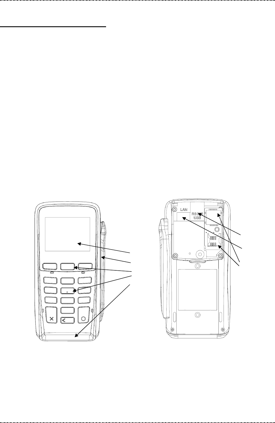
PIN Pad components
This PIN Pad is composed of the following components:
(1). LCD display with 320 * 240 resolution.
(2). Magnetic stripe reader swiping slot.
(3). 13 key telephone-style keypad and 3 function keys.
(4). Smart card reader inserting slot.
(5). Primary communication interface (RS232 or USB), with protection cover
(6). Ethernet LAN Port
(1)
(2)
(3)
(4)
(5)
(6)
(7)

PIN Pad 791 Programmer’s Manual (PCI POS-A) UDN PM0103-U Rev. 06
Section 1 – Introduction 2015-04-20
Page12
Uniform Industrial Corp. Proprietary and Confidential Total 342 pages
(7). Three secure access module (SAM) slots, with protection cover.
Display
The 320*240 pixels TFT LCD is capable of displaying characters and graphic. For displaying characters,
It provides ASCII 8*8 character set for range 0x20~0x7E, 8*16, 16*16, 16*24 character set for range
0x20~0xFF.
Keypad
The PIN Pad uses its 16 keys to accept commands. For each key pressed, there will be a short beep to
confirm that key is accepted. The following diagram shows layout of the keys.
1 2 3
4 5 6
7 8 9
CAN
0
ENTER
CLR
[CAN] (Cancel) button will abort PIN entering transactions or magnetic card swiping actions, and cause
PP791 back to idle state.
[CLR] (Clear) button will reset PIN input when doing PIN entry transactions.
[F1] The F1 button is treated as “move up” when dealing with function menu (such as diagnostic
mode or EMV Lv2 transaction menu). With customized application, system integrators can define
its usage by themselves.
[F2] The F2 button is treated as “go back” when dealing with function menu. With customized
application, system integrators can define its usage by themselves.
[F3] The F3 button is treated as “move down” when dealing with function menu. With customized
application, system integrators can define its usage by themselves.
Communication Interface
PP791 has two communication interfaces:
1. A detachable 9-pin Mini-DIN interface which can be used to connect proprietary RS232/USB auto
selecting cable for power feeding and data exchange with host device.
2. A RJ-45 Ethernet jack for TCP/IP communication.
Magnetic and Smart Card reader
The smart card reader of PP791 can accept EMV Level 2 compatible smart cards for offline transaction,
F1 F2 F3

PIN Pad 791 Programmer’s Manual (PCI POS-A) UDN PM0103-U Rev. 06
Section 1 – Introduction 2015-04-20
Page13
Uniform Industrial Corp. Proprietary and Confidential Total 342 pages
or exchange APDU packets with EMV Level 1 compatible smart cards via ICC-related commands. It also
reads ISO 7811 compatible magnetic cards for legacy online debit / credit card operation.
Smart card and Security Access Module (SAM) interfaces
PP791 provides three SAM interfaces (optional) for customer usage. System Integrators can use PP791
internal API or SAM-related commands to switch between different slots and exchange APDU.
Tamper Evidence and Tamper Responsive
PP791 is compatible with “Payment Card Industry (PCI) POS PIN entry device security requirement”
version 3.0. Per this requirement, PP791 will detect tampering attempts by its multiple security design. If
tamper is detected, security subsystem will cause the automatic and immediate erasure of all secret
information contained in it. Such as master keys, DUKPT key, personalization information and so on.
Without security information PP791 will not work anymore. A user should contact system
integrator or vendor representative for RMA when a PP791 was tampered.

PIN Pad 791 Programmer’s Manual (PCI POS-A) UDN PM0103-U Rev. 06
Section 2 –System Manager 2015-04-20
Page14
Uniform Industrial Corp. Proprietary and Confidential Total 342 pages
Section 2 System Manager
Introduction
The system manager is a resident process launched automatically when PP791 boot up. It will manage
the download and execution of other application, do basic settings, and self tests.
After system booted up and the startup application is launched, user can press “ENT + 1” (press ENT
key and ‘1’ at the same time), then input dual passwords of system manager to enter system manager
menu. (The default password will be sent to legal user by secure method).
NOTE 1: Enter system manager will terminate the current application.
NOTE 2: System manager will exit and re-launch startup application if no input over 60 seconds.
Security management
1. Personalization and tamper detection
Each PP791 is “personalized” (create an AES key randomly for sensitive data protection) before
delivery. Every time PP791 boot up, system manager will check the personalization status and
existence of this AES key. If device is tampered, security mechanism will erase the AES key and
invalid personalization status, then reboot. After reboot, system manager will see the change and
show following message (tamper evidence mode):
“System has tampered, you shall release it before you can normally use.”
In this situation, user can press “ENT + 1” (press ENT key and ‘1’ at the same time), then input
dual passwords of system manager to exit tamper evidence mode.
When exiting tamper evidence mode, PP791 will be re-personalized. All keys will be erased.
2. Certificate management
Every application in the PP791 should have digital signature (sha256 hash encrypted by 2048bit
RSA key) The system process (system manager and PP791 appl.,) will be verified by a fixed
system certificate resident in system kernel, and user applications will be verified by user-loaded
certificates, which is managed by system manager.
The certificate hierarchy of PP791 contains:
Vendor certificate: This certificate is created by user (i.e. system integrator or bank), it verifies user
applications when downloading application and launching application.
Intermediate certificate: This certificate is issued by intermediate CA, it verifies vendor certificate
every time when system manager starts.
Root certificate: This certificate is issued by root CA, by default, PP791 have a root certificate
resident in system kernel. But users can load their own root certificate along with intermediate and
vendor certificate in the same trust chain. It verifies intermediate certificate every time when
system manager starts.

PIN Pad 791 Programmer’s Manual (PCI POS-A) UDN PM0103-U Rev. 06
Section 2 –System Manager 2015-04-20
Page15
Uniform Industrial Corp. Proprietary and Confidential Total 342 pages
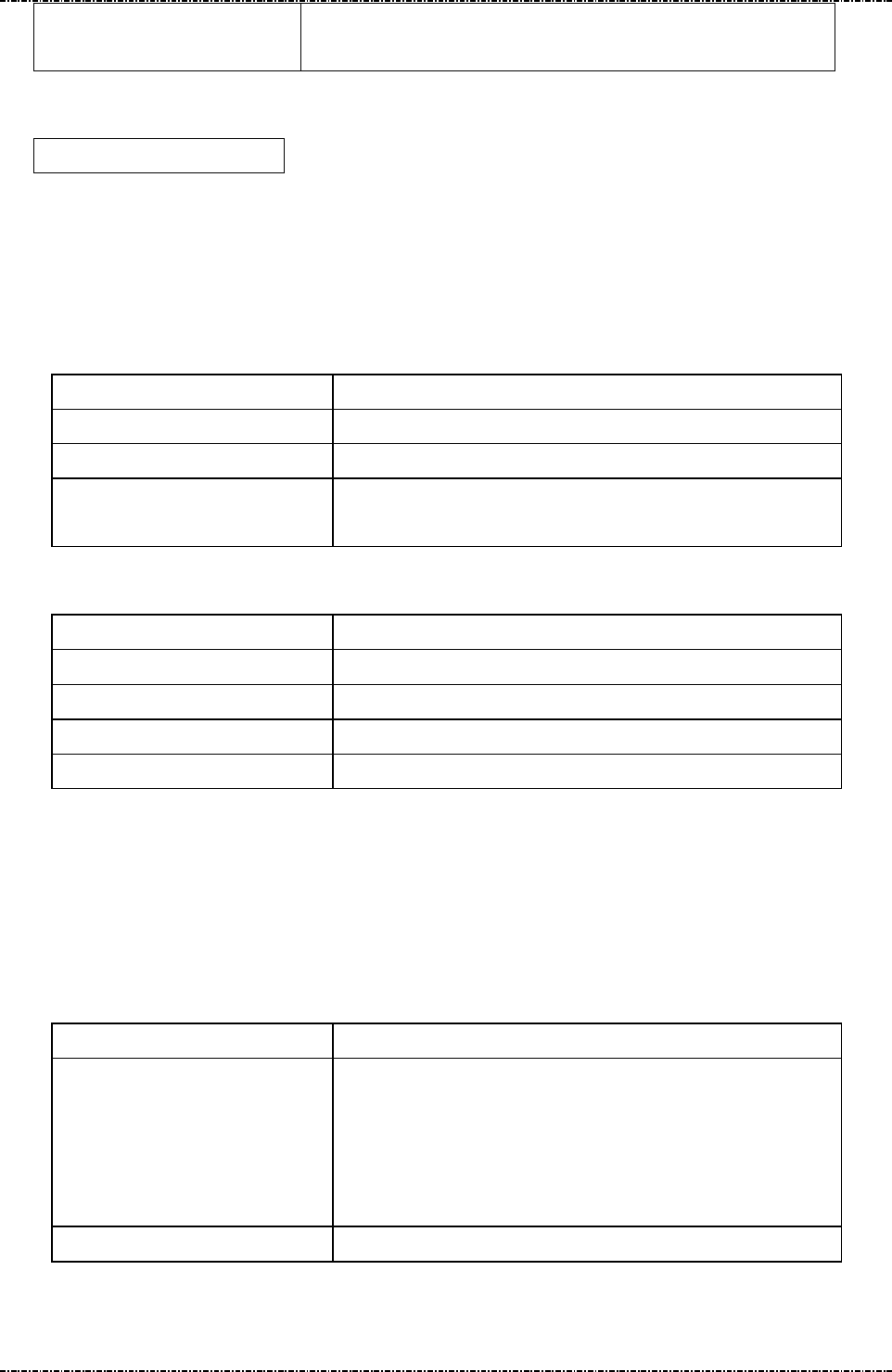
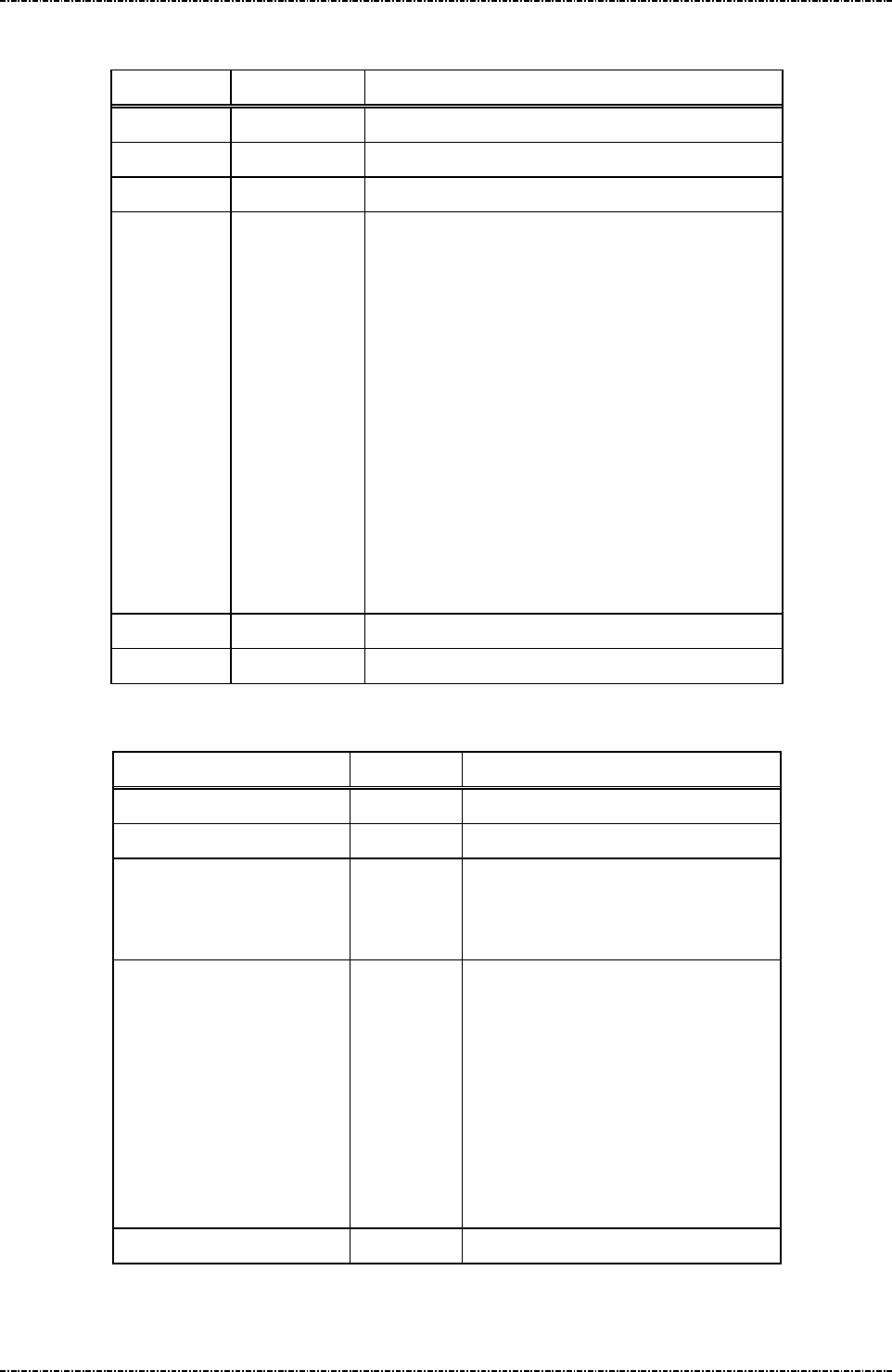
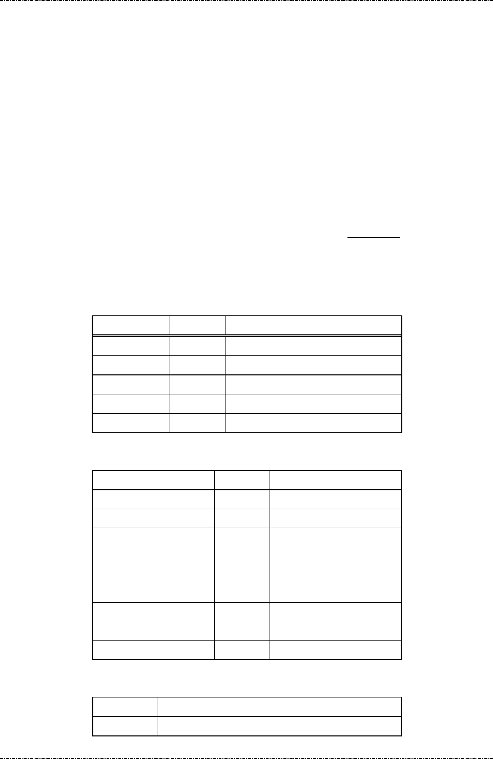
Main menu of system manager
DISPLAY ACTION
Key Injection Do clear text key load.
Download Do firmware updates.
Date & Time Adjust system date, time, and time zone.
Setting Set up system manager options.
System Info Show firmware version, TCP/IP settings, and certificate names.
Self Test Do basical hardware test.
Change Password Change system manager password.
Prepare downloading
User has to use system manager to download applications, graphics, or update system components.
There are two methods to download: via TCP/IP (need to a FTP server, and correctly setup IP address
and FTP config scripts by “Setting” menu).
Prepare FTP server:
User can establish a FTP server on any computer that already connected to LAN and have valid IP
address. The server should have a directory (i.e. ftproot/pub) that contains following directory (case
sensitive):
1. certs: Contains certificate files with pre-defined names: “appl_vendor.crt” for vendor
certificate; “appl_inter.crt” for intermediate certificate; “custom_root.crt” for customized
root certificate if needed; “certificates.tar.gz” for package download if needed.
2. graphics: Contains a “graphics.lst” file and picture packages in tar.gz format.
3. system: Contains system update files provided by UIC.
The list files (graphics.lst) are pure text file, with one name per line:
Graph_01
Graph_02
.....
When PP791 reads “Graph_01”, in graphics.lst, it will go to server to find “Graph_01.tar.gz”.
Prepare FTP config script:
PP791 can manage multiple FTP settings by selecting config script. Each config script should have the
extension name “.cfg”, with following format:
host=xxx.xxx.xxx.xxx
port=21
user=anonymous
IP address of FTP server.
FTP port number.
FTP login name.
PIN Pad 791 Programmer’s Manual (PCI POS-A) UDN PM0103-U Rev. 06
Section 2 –System Manager 2015-04-20
Page16
Uniform Industrial Corp. Proprietary and Confidential Total 342 pages
password=xxxxxx
path=/pub
FTP login password.
Directory name that contains appls, certs, graphics and system.
PP791 will read an “ftp_setting_file” which contains one ftp config script name, and use it as
default FTP setting. The factory default of ftp_setting_file is:
ftp_site1.cfg
(As a result, system manager will read server IP address, port, username and password from this file).
The FTP setting file and config scripts can by edited by system manager.
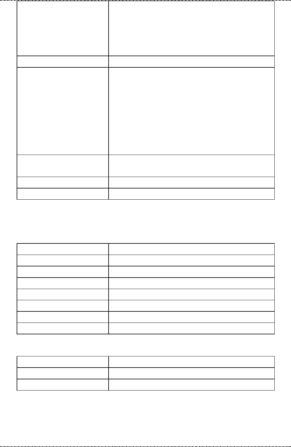
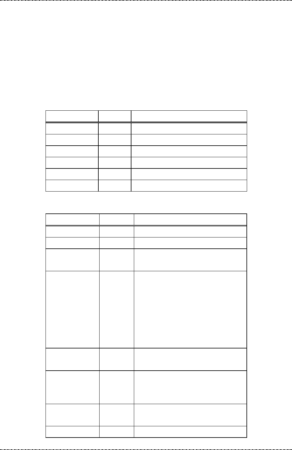
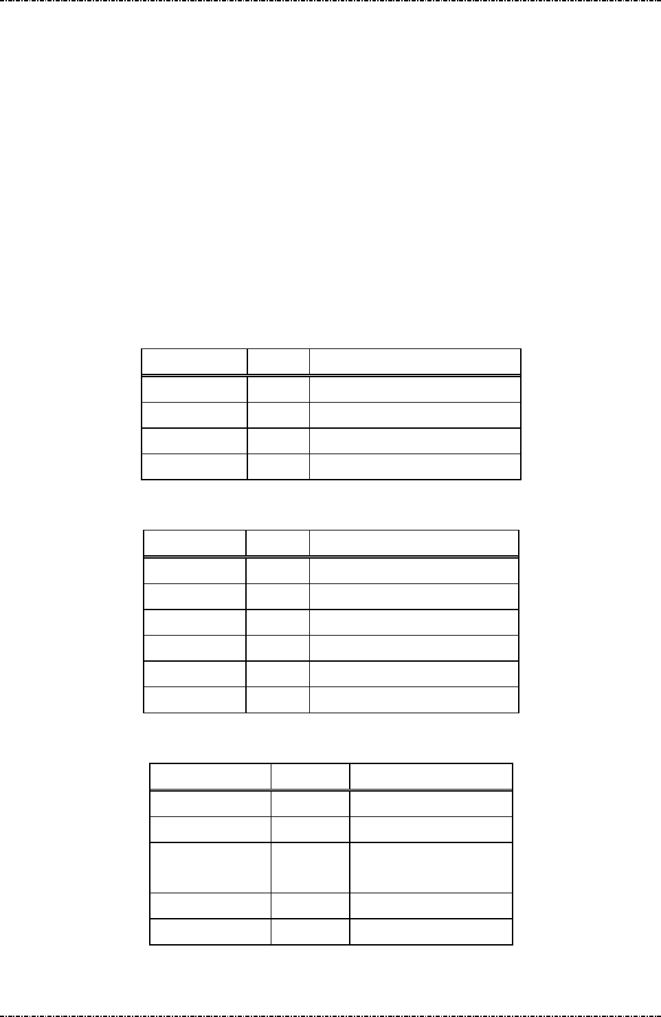
“Download” menu
DISPLAY ACTION
Download System Select download method; Then show system update menu.
Download Graphics Select download method; Then show graphics download menu.
Download Certs Select download method; Then show certificates download
menu
“Download System” menu:
DISPLAY ACTION
PIN Pad 791 Update PP791 application.
System Manager Update System Manager.
Linux Kernel Update Linux kernel of PP791.
Root Filesystem Update system files of PP791.
Note: these update files will be signed by UIC and verified by built-in UIC system certificate.
“Download Graphics” menu:
The graphic package (.tar.gz format) should have a subdirectory:
jpeg: JPEG pictures (Refer to Jxx commands of PP791)
DISPLAY ACTION
Download Graphics Display graphic package names from “graphics.lst” resident in
PP791. Use [F1] ~ [F3] to navigate, [ENT] to start download
graphic package.
If download success, system manager will copy graphics in the
package file to system graphics directory.
Download Graphics List
Download “graphics.lst” from server.
“Download Certs” menu:

PIN Pad 791 Programmer’s Manual (PCI POS-A) UDN PM0103-U Rev. 06
Section 2 –System Manager 2015-04-20
Page17
Uniform Industrial Corp. Proprietary and Confidential Total 342 pages
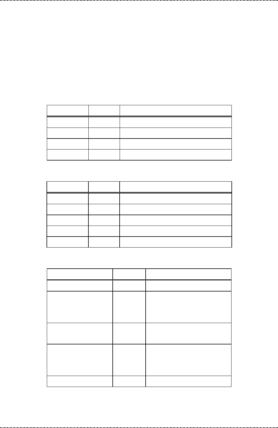
DISPLAY ACTION
Download Vendor Cert. Download “appl_vendor.crt”
Download Intermediate
Cert.
Download “appl_inter.crt”
View current cert. CN View CN (common name) of current intermediate and vendor
certificate.
Lock/Unlock Cert. CN This option , if enabled, will cause system manager to check the
CN (common name) field of newly downloaded certificate; if
new CN is different than old one, system manager will reject
this certificate.
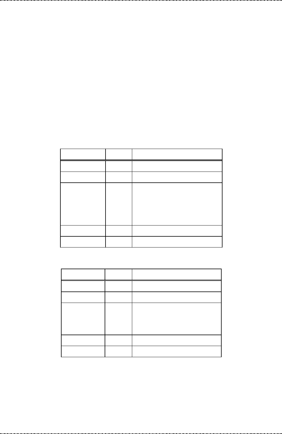
“Date & Time” menu
DISPLAY ACTION
Current date/time Display current time zone,
Current RTC time (UTC).
Current Local time.
Set time zone 1. Enter the name of local time zone. (3~6 bytes)
2. Input the time offsets from UTC. (use [F1] to add minus sign)
3. Enter the name of Daylight Saving Time (DST) or press
[CAN] to skip the related settings of DST.
4. Input the time offsets of DST from UTC.
5. Enter the start date and time of DST.
6. Enter the date and time to set the end of DST.
Set date/time 1. Enter year, month, day, hour (24h format), minute, second.
2. Press [ENT] to set time, or [CAN] to cancel.
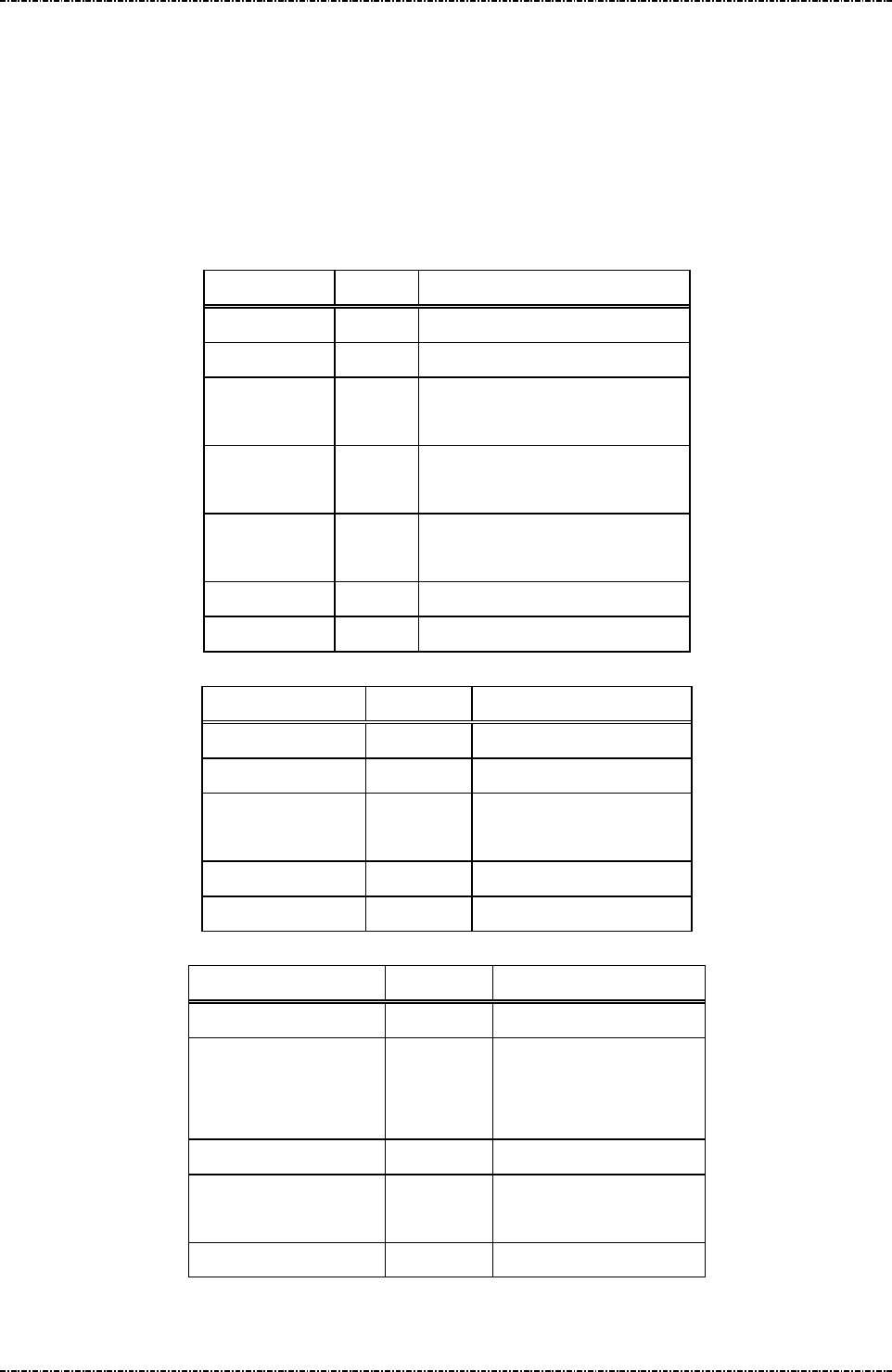
“Setting” menu
DISPLAY ACTION
Set DHCP / IP Bring up sub menu of basic TCP/IP settings
[Set DHCP]
Enable or disable DHCP client of PP791. This setting will effect
after reboot.
[Set Local IP]
Set fixed IP address of PP791 if DHCP disabled.
[Set Gateway IP]
PIN Pad 791 Programmer’s Manual (PCI POS-A) UDN PM0103-U Rev. 06
Section 2 –System Manager 2015-04-20
Page18
Uniform Industrial Corp. Proprietary and Confidential Total 342 pages
Set gateway IP address of PP791 if DHCP disabled.
[Set Subnet Mask]
Set subnet mask of PP791 if DHCP disabled.
[Set DNS Server]
Set DNS server address of PP791 if DHCP disabled.
Set Console Enable or disable linux command console.
Set FTP [Set FTP Server]
Set default FTP server IP address and save to detault FTP
config script when user selected “Save all setting”.
[Select FTP script]
System manager will show a list of FTP config scripts resident
in PP791, use [F1] ~ [F3] to navigate, and [ENT] to select one
as defaut FTP config script.
NOTE: The settings in the script will take effect immediately.
Set Leav
e Before Run
Appl
If this option enabled, system manager will leave interactive
menu before run application.
Display all setting Display current value of each “Setting” menu.
Save all setting? Save new settings.
“System Info” menu
DISPLAY ACTION
Kernel PP791 Linux kernel version.
RFS PP791 root file system version.
SysMgr PP791 system manager version.
PP791 PP791 appication version.
Serial# Serial number of this device.
MAC Ethernet MAC address of this device.
IP Addr Current IP address of this device.
After 10 seconds passed or user press any key, PP791 will show the certificate information:
(The certificate info has 3 pages: for vendor, intermediate, and root certificate).
DISPLAY ACTION
Cert. CN “Common Name” field of certificate
Cert. Hash (partial) Most significant 4 bytes of the SHA-1 hash of this certificate.
“Self Test” menu

PIN Pad 791 Programmer’s Manual (PCI POS-A) UDN PM0103-U Rev. 06
Section 2 –System Manager 2015-04-20
Page19
Uniform Industrial Corp. Proprietary and Confidential Total 342 pages
DISPLAY ACTION
Display Test Display black screen, then display test string on LCD.
Keypad Test Display keypad input on LCD, press [CAN] to exit.
MSR Test Test MSR swipe; the PAN of payment track will be partially
masked.
ICC Test Test smart card powerup and display its ATR.
RFID Test Test tap for RFID credit cards such as visa wave and PayPass;
the PAN of payment track will be partially masked.
COM1 Test Select baud rate, then PP791 will send a test pattern thru
COM1. User should echo this test pattern. PP791 will show the
compare result.
TCP Test Enter any IP address, PP791 will ping 4 times to see if network
is accessable.
“Change Password” menu
DISPLAY ACTION
Change Password 1 Change 1st password of system manager.
Change Password 2 Change 2nd password of system manager.

PIN Pad 791 Programmer’s Manual (PCI POS-A) UDN PM0103-U Rev. 06
Section 3 –PP791 Setup & Diagnostic Menu 2015-04-20
Page20
Uniform Industrial Corp. Proprietary and Confidential Total 342 pages
Section 3 PP791 Setup & Diagnostic Menu
Call up Diagnostic Menu
Press function key [CLR] + [3] (quickly press ‘3’ after [CLR] released) of PP791 will call up diagnostic
menu when PP791 in idle state. The default 2 passwords for diagnostic menu are “87806799” (both
passwords)
DISPLAY ACTION
(Idle prompt) Power on.
Press [CLR]+[3]
Password 1? Input first setup password and press [ENTER]
Password 2? Input second setup password and press [ENTER]
HW Tests
Display Info
Setup COM Port
Set LCD Backlight
Logo Setup
Update Password
Set Keypad Beep
Use [F1] ,[F3] to scroll up and down.
[F2] to go back.
[ENTER] to execute.
Diagnostic Menu 1: HW Tests
DISPLAY ACTION
Display Test Display two pages of test pattern:
First page is turn on all pixels to check if there are any dot
damage. Press any key or wait 10 sec to continue.
Second page shows PP791 character sets. Press any key or wait
5 sec to leave.
Keypad Test PP791 will echo user’s input key at line 2.
Press [CAN] to leave this test.
MSR Test PP791 will show “MSR TEST –SWIPE” on LCD and wait for
user to swipe any magnetic stripe card. After card swiped, a
submenu will displayed to let user check track 1,2,3
independently.
ICC Test Insert an EMV Lv1 compatible smart card into primary card
slot, and then select this function. PP791 will display its ATR
string on LCD for check.

PIN Pad 791 Programmer’s Manual (PCI POS-A) UDN PM0103-U Rev. 06
Section 3 –PP791 Setup & Diagnostic Menu 2015-04-20
Page21
Uniform Industrial Corp. Proprietary and Confidential Total 342 pages
Diagnostic Menu 2: Display Info
DISPLAY ACTION
Show COM Param. Display current COM port setting on PP791.
COM1: Primary interface (if primary interface is USB, the
value will be 9600, N, 8, 1)
Show SerialNum Display current serial number. Refer to message 06.
Show Version Display current firmware version
SENSOR STATUS Display the sensor setting information
Diagnostic Menu 3: Setup COM Port
DISPLAY ACTION
Set COM1 Param
A sub menu will show up:
Set Baudrate
Set Mode
Enter into “Set Baudrate” to set COM1 baud rate
Press keypad to set baud rate:
‘1’ = 1200bps
‘2’ = 2400bps
‘3’ = 4800bps
‘4’ = 9600bps
‘5’ = 19200bps
‘6’ = 38400bps
‘7’ = 57600bps
‘8’ = 115200bps

PIN Pad 791 Programmer’s Manual (PCI POS-A) UDN PM0103-U Rev. 06
Section 3 –PP791 Setup & Diagnostic Menu 2015-04-20
Page22
Uniform Industrial Corp. Proprietary and Confidential Total 342 pages
Set COM1 Param
(Continued)
Enter into “Set Mode” to set COM1 operation mode
Press keypad to set COM1 operation mode:
‘1’ = ‘8’, ‘N’, ‘1’ (8-bit data length, none parity, 1 stop bit)
‘2’ = ‘7’, ‘E’, ‘1’ (8-bit data length, even parity, 1 stop bit)
‘3’ = ‘7’, ‘O’, ‘1’ (8-bit data length, odd parity, 1 stop bit)
‘4’ = ‘8’, ‘N’, ‘1’ with handshake
‘5’ = ‘7’, ‘E’, ‘1’ with handshake
‘6’ = ‘7’, ‘O’, ‘1’ with handshake
The COM1 on PP791 supports three handshake modes:
1. RTS flow control
2. XON-XOFF flow control
3. RTS/XON-XOFF flow control
The default parameter of COM1 on PP791 is “9600bps, none
parity, 8 data bits, 1 stop bit”. User can use command message
10 to change this setting remotely.
Diagnostic Menu 4: Set LCD Backlight
DISPLAY ACTION
Light Always ON
Light Auto OFF
First item will set LCD backlight always on. This setting is the
same with message Z9 with parameter 1.
Second item will set PP791 enable its backlight in following
situation:
a. Any key is pressed.
b. PIN entry command is working
c. Selecting Menu.
And backlight will automatically turn off after 3 seconds of
above operation ends.

PIN Pad 791 Programmer’s Manual (PCI POS-A) UDN PM0103-U Rev. 06
Section 3 –PP791 Setup & Diagnostic Menu 2015-04-20
Page23
Uniform Industrial Corp. Proprietary and Confidential Total 342 pages
Diagnostic Menu 5: Logo Setup
DISPLAY ACTION
Idle Logo ON/OFF Enable or disable graphical idle logo.
(The logo image is defined by command J7)
Diagnostic Menu 6: Setup Password
DISPLAY ACTION
Update Password1 PP791 will show following message:
NEW PASSWD
****
CONFIRM PASSWD
****
User should press 1st password, press [ENTER] to enter 2nd
password, then press [ENTER] to finish input. If two passwords
mismatch the password will not be changed. Password must
have 6 characters at least, with maximum 16 characters.
Update Password2 PP791 will show following message:
NEW PASSWD
****
CONFIRM PASSWD
****
(Usage is the same with password 1.)
Diagnostic Menu 7: Set Keypad Beep
DISPLAY ACTION
Beep ON Key press with beep.
Beep OFF Key press without beep.

PIN Pad 791 Programmer’s Manual (PCI POS-A) UDN PM0103-U Rev. 06
Section 3 –PP791 Setup & Diagnostic Menu 2015-04-20
Page24
Uniform Industrial Corp. Proprietary and Confidential Total 342 pages
About USB virtual COM port (only applied on USB version)
PP791 USB version will identify itself as a virtual COM port for Windows 2000/XP device enumeration.
When Windows requests PP791’s device driver, please provide a directory name which contains PP791
USB driver, and answer “proceed anyway” when prompted with driver certification questions.
The baud rate of PP791 virtual COM port is determined by the application program. When AP calls
Windows API to open COM port, PP791 and Windows virtual COM port driver will adjust its baud rate
according to the parameters sent to API function.
Call up Interface Setting Menu
In a WIFI/Bluetooth capable PP791, press function key [CLR] + [F2] (quickly press ‘F2’ after [CLR]
released) of PP791 will call up interface setting menu when PP791 in idle state.
DISPLAY ACTION
(Idle prompt) Power on.
Press [CLR]+[F2]
COMM. Interface Switch
WIFI Setting
Bluetooth Setting
Status
Use [F1] ,[F3] to scroll up and down.
[F2] to go back.
[ENTER] to execute. Interface Setting
Interface Setting Menu 1: COMM. Interface Switch
DISPLAY ACTION
COM PP791 communicate with Terminal via COM.
WIFI PP791 communicate with Terminal via WIFI.
Bluetooth PP791 communicate with Terminal via Bluetooth.
Use Default Use Default interface which is COM.
Interface Setting Menu 2: WIFI Setting
DISPLAY ACTION
Discover Server PP791 will scan all available server on the same wireless lan
(Refer to PIN PAD 791 Multicast Programmer’s Manual)and
show the result on the screen. As user choose a server, the
configuration(Server IP and Server Port) of Server will be set
into PP791, and then user can use “Connect” option to connect
to the server.
Set Server IP Manually set the IP address of Server which you want to
connect.

PIN Pad 791 Programmer’s Manual (PCI POS-A) UDN PM0103-U Rev. 06
Section 3 –PP791 Setup & Diagnostic Menu 2015-04-20
Page25
Uniform Industrial Corp. Proprietary and Confidential Total 342 pages
Set Server Port Manually set the Port number of Server which you want to
connect.
Connect Connect to the Server.
Disconnect Disconnect with the Server.
Status Display the WIFI setting information
Interface Setting 3: Bluetooth Setting
DISPLAY ACTION
Choose Devices 1. Scan Devices: Get the BT Device name, and MAC address.
2. Choose Devices: Input the 0~ 9 to choose the BT device.
PIN Setup 1. Read Device PIN: Default PIN is “123456”
Change Device PIN
Connect Device Connect to BT Device
Disconnect Device Disconnect with BT Device
Interface Setting Menu 4: Status

PIN Pad 791 Programmer’s Manual (PCI POS-A) UDN PM0103-U Rev. 06
Section 4 – Message format 2015-04-20
Page26
Uniform Industrial Corp. Proprietary and Confidential Total 342 pages
Section 4 Message format
This chapter details the format of messages exchanged between the host and PIN Pad.
Notation Conventions
The following conventions are used to make the description of messages more readable:
Control Codes
Control codes (non-displayable codes) are represented by two to three capital letters enclosed in angled
brackets “<>“. This PIN Pad uses 12 control codes in total. Their actual code, when referenced, is
represented by two hex digits enclosed in angled brackets, <0F> for example. The following table lists
their usage and value in hex codes.
CODE HEX VALUE
USAGE
STX 02 Denotes the beginning of a message frame
ETX 03 Denotes the ending of a message frame
EOT 04 Indicates communication session terminated
ACK 06 Acknowledge of message received
SI 0F Denotes the beginning of a message frame
SO 0E Denotes the ending of a message frame
NAK 15 Indicates invalid message received
SUB 1A Message parameter follows
FS 1C Field separator
GS 1D Message ID follows
DC1 11 Used for Z2 message, enable inverse mode.
DC2 12 Used for Z2 message, disable inverse mode.
[LRC]
Each message frame transmitted is followed by an LRC byte to detect communication error. This byte
should be regarded as part of the message frame but comes after the ending delimiter character. [LRC]
is used to represents this LRC byte in describing message frames.
LRC is calculated as an XORed value of every byte after start code in the message frame except itself,
that means from the next byte of <STX> or <SI> through the <ETX> or <SO> byte.
[item]
A descriptive item name enclosed in bracket denotes a string or data byte that has no fixed value.

PIN Pad 791 Programmer’s Manual (PCI POS-A) UDN PM0103-U Rev. 06
Section 4 – Message format 2015-04-20
Page27
Uniform Industrial Corp. Proprietary and Confidential Total 342 pages
Message frame summary
Data exchanged between PIN Pad and host computer are grouped into “message frames”. Each
message frame has one of the two frame formats listed below:
<STX>[message ID][data]<ETX>[LRC]
<SI>[message ID][data]<SO>[LRC]
Each type of message has a unique value in its message ID field. In the following texts, we reference a
message type by its message ID value, e.g. “message 70”.
Message type
Messages exchanged between the PIN Pad and the HOST can be divided into two categories.
One is for administration and maintenance, in general administrative messages have <SI> packet
header and will return message to HOST by the same message ID.
The other is for various transactions, in general transaction messages have <STX> packet header, and
comes in pair. Even number message packets sends command and data to PIN pad, then odd number
message packets returns the result.
Time-out
Whenever the PIN Pad sends a message, a response (<ACK> character for acknowledgement or
<NAK> character if LRC error occurred) from host is expected. If the PIN Pad does not receive a
response within 5 seconds, it will retransmit the last packet. If PIN pad does not receive <ACK> or
<NAK> after two retransmit attempts, it will send <EOT> character and this communication session will
be terminated.
Transmission Error
The PIN Pad expects the host computer to send a NAK when the host decides that an invalid frame is
received. When the PIN Pad receives a NAK, it will retransmit its last message. If the message
retransmitted is invalid again, then a NAK should be sent by host to request for another try. The PIN Pad
will keep on retransmitting until an <ACK> or <EOT> is received.
Packet Error
When PIN pad received a good transmission but invalid packet (wrong message id) it will ignore the
packet. If the packet has acceptable message id but have wrong format. PIN pad will send <EOT> as
error message. When in PIN entry functions it will send more detail error code.

PIN Pad 791 Programmer’s Manual (PCI POS-A) UDN PM0103-U Rev. 06
Section 5 – Administration and maintenance messages 2015-04-20
Page28
Uniform Industrial Corp. Proprietary and Confidential Total 342 pages
Section 5 Administration and maintenance messages
Message 02 Load Master Key
Format: <SI>02[Key ID][Key value] <FS>[Usage][Mode]<SO>[LRC]
(with clear text key)
<SI>02[Key ID][Key value (ANSI TR31 format)]<SO>[LRC]
(with encrypted key)
Message length: Variable (38 to 94 bytes).
Usage: Load Master Keys into PP791.
PP791 can store 32 master keys (16 of them not used by PP791 application); each has
a one digit ID. Master keys are divided into three groups of different functions. Refer to
Appendix A: Key management for key usage and ID definition.
PP791 implements multiple security measures to conform Payment Card Industry (PCI)
security requirement. In order to load clear text master keys, two authorized people
with their password are required. Otherwise the user must issue message 02 with
encrypted key value (ANSI TR31 format). See next entity “Symmetric Keys Loading
Authentication” for detailed information.
Note: 1. The [key value] field’s format is ASCII string with range ‘0’-‘9’, ‘A’-‘V’, which
represents a hexadecimal byte in two characters, i.e. “1F” represents 0x1F.
2. PP791 requires key loading key (master key #F) to be TDES.
3. Pass key loading authentication and then load new clear text master key will erase
all other master keys, to prevent malicious key substitution. For more information refer
to “Symmetric Keys Loading Authentication” at page 24.

PIN Pad 791 Programmer’s Manual (PCI POS-A) UDN PM0103-U Rev. 06
Section 5 – Administration and maintenance messages 2015-04-20
Page29
Uniform Industrial Corp. Proprietary and Confidential Total 342 pages
Message element:
Request fame (HOST to PP791)
Field Length Value and description
<SI> 1 <0F>
02 2 Message ID
[Key ID] 1 ‘0’ to ‘9’, ‘A’ to ‘V’ (A and H to V is not used)
[Key value]
Var. Hexadecimal string for key value.
Clear text format: 32 bytes for double length, 48
bytes for triple length.
TR31 format: 56 bytes for single length, 72 bytes
for double length, 88 bytes for triple length.
<FS> 1 Field separator.
(Optional, only available in clear text format frame
if following [Usage] and [Mode] exists)
[Usage] 2 (Optional: ANSI TR-31 key usage for clear text
frame.)
Available value are:
“K0” for key encryption. (id 0 ~ 9, B ~ G)
“P0” for PIN encryption. (id 0 ~ 9)
“M3” for MAC calculation. (id B ~ E)
“D0” for data encryption. (id G)
If omitted, default value is “K0”
[Mode] 1 (Optional: ANSI TR-31 key mode for clear text
frame.)
Available value are:
‘D’ for decryption only. (K0 keys)
‘E’ for encryption only (P0 / D0 keys)
‘G’ for MAC generation only (M3 keys)
‘V’ for MAC verification only (M3 keys)
If omitted, default value is ‘D’.
<SO> 1 <0E>
[LRC] 1 Checksum
PIN Pad 791 Programmer’s Manual (PCI POS-A) UDN PM0103-U Rev. 06
Section 5 – Administration and maintenance messages 2015-04-20
Page30
Uniform Industrial Corp. Proprietary and Confidential Total 342 pages
Response fame – Error message (HOST to PP791)
Field Length Value and description
<SI> 1 <0F>
02 2 Message ID
? 1
[Err msg] 1 ‘2’: Key duplicate.
‘3’: Internal fail: fail to allocate memory
‘4’: Internal fail: fail to read key structure
‘7’: Fail to decrypt key value.
‘A’: TR31 format error.
‘B’: Insecure key inject. (New key is longer than
the key used to protect it.)
‘C’: Fail to verify MAC value.
‘D’: KLK does not exist / The selected key (KLK)
is not with usage “K0”
‘E’: Incompatible key usage.
‘F’: Key loading count over limit.
<SO> 1 <0E>
[LRC] 1 Checksum
Message flow:
HOST Direction PIN Pad
Message 02 (request frame)
<ACK> /<NAK>/<EOT>
Processing request.
If format error, send <EOT> and end.
Message 02 (echo of request frame).
Verify echo frame.
If verify ok, send <ACK>.
If packet LRC error, send
<NAK>.
If host want to cancel key
loading procedure, send
<EOT>.
Save key value and send <EOT>

PIN Pad 791 Programmer’s Manual (PCI POS-A) UDN PM0103-U Rev. 06
Section 5 – Administration and maintenance messages 2015-04-20
Page31
Uniform Industrial Corp. Proprietary and Confidential Total 342 pages
Example:
Clear Text
Master key to be loaded: 1919191919191919 5B5B5B5B5B5B5B5B
The Key ID you want to load: 0
The resulting 02 message : <SI>02019191919191919195B5B5B5B5B5B5B5B<SO>[LRC]
Encrypted (ANSI TR-31 2005 Key Variant Binding Method)
Key encrypting key (Mkey #F): 1919191919191919 5B5B5B5B5B5B5B5B
Master key to be loaded (K0): AA55AA55AA55AA55 3434343434343434
Key Block Header (KBH): (ASCII) A0072K0TD00N0000
TDES CBC encrypted key value: 7D2D21FC9ECD3EEC BB0A2615BD8F0560 5722120BDFF2CCAC
Left 4 bytes of MAC value: 319C3198
The Key ID you want to load: 0
The resulting 02 message:
<SI>020A0072K0TD00N00007D2D21FC9ECD3EECBB0A2615BD8F05605722120BDFF2CCAC319C3
918 <SO>[LRC]
Encrypted (ANSI TR-31 2010 Key Derivation Binding Method)
Key condition: Load a double length PIN encryption key to key position #1
Key block protection key (KBPK): 1919191919191919 5B5B5B5B5B5B5B5B
PIN encryption key to be loaded: AA55AA55AA55AA55 3434343434343434
Padded key data: 0080 AA55AA55AA55AA55 3434343434343434 1C2965473CE2
Key Block Header (KBH): (ASCII) B0080P0TE00N0000
Derived Key block encryption key (KBEK): DB7F2A99D5647A7D D3EDFE3DA7CF5B21
Derived Key block MAC key (KBMK): 87EE6C0795954446 A34A0BB5F305BCE1
(See Appendix A for detail derive process)
CMAC of (KBH + Padded key data), using KBMK: EA391E5834C1AA0C
(See Appendix A for detail CMAC algorithm)
Use CMAC as IV to do TDES CBC encryption on padded key data, using KBEK:
Encrypted key data: 3C4F5024C59C182F 7165BC870FCB7F63 456AAE07DB736C32
The resulting 02 message:
<0F>021B0080P0TE00N0000 3C4F5024C59C182F 7165BC870FCB7F63 456AAE07DB736C32
EA391E5834C1AA0C<0E>

PIN Pad 791 Programmer’s Manual (PCI POS-A) UDN PM0103-U Rev. 06
Section 5 – Administration and maintenance messages 2015-04-20
Page32
Uniform Industrial Corp. Proprietary and Confidential Total 342 pages
Symmetric Keys Loading Authentication
In order to make PP791 accept clear text key loading frame, the key loading authentication must be
processed.
[Enter key loading authentication menu]
Press [CLR]+[2] on the keypad of PP791, then PP791 will show key injection authentication login screen
as following:
ENTER PASSWORD 1:
(Default password will be sent to authentic owner separately)
The first authorized person come to enter 1st password on keypad and press [ENTER].
Then PP791 will prompt to enter 2nd password if 1st password is correct. If 2nd password is correct, too,
PP791 will enter key loading mode and show following menu:
KEY INJECT MODE
UPDATE PASSWORD1
UPDATE PASSWORD2
INJECT MKEY/IPEK
Use [F1] and [F3] key to navigate light bar to “Inject MKEY/IPEK”, then press [ENTER]. Then user is free
to load clear text master key by message 02, or load DUKPT initial key by message 90 and 94.
[Timing constraint and message constraint of Key Inject Mode]
According to PCI security requirement, PIN pad cannot stay in Key Inject Mode forever. Thus when
PP791 entered Key Inject Mode, its internal timer will start to countdown, and its operating system will
monitor specific message packets. If any one of following criteria is matched, PP791 will exit Key Inject
Mode and reject message 02(clear text form) and 90, 94 command:
1. When PIN pad idled for 60seconds, it will exit Key Inject Mode. (Each time 02 / 90 / 94 / 08 / 96 is
succeeded, the 60 seconds counter will reset to 60 again.)
2. When PIN pad has been in Key Inject Mode for 15 minutes. It will unconditionally exit Key Inject
Mode.
3. When PIN pad receives messages other than 02 / 90 / 94 / 08 / 86, it will exit Key Inject Mode.
4. When user pressed CAN key on keypad, it will exit key inject mode.
[Master key substitution protection]
When user entered Key Inject Mode, PIN pad operating system will set up a new “Key Injecting Session”.
The first injected clear text master key in a new session will erase all other master keys.
The other master keys loaded in the same session will not erase any other master key.
DUKPT key set 0 and set 1 will not erase each other.

PIN Pad 791 Programmer’s Manual (PCI POS-A) UDN PM0103-U Rev. 06
Section 5 – Administration and maintenance messages 2015-04-20
Page33
Uniform Industrial Corp. Proprietary and Confidential Total 342 pages
Example flow to load master keys with security:
In the following example we assume a bank receives a new PP791 and wants to initialize it before deploy.
And want to update some master keys after its deployed. We also assume the master key to be loaded is
position 0 and position F; their values are already stored in a Tamper Resistant Security Module (TRSM)
in a secure way.
1. The bank must generate two passwords, and make two authorized people to keep them separately.
2. Authorized people must enter KEY INJECT AUTH menu and change password 1 and password 2.
3. After password changed, connect PIN Pad to TRSM, enter KEY INJECT AUTH menu again and
choose Inject MKEY/IPEK function.
4. Operate TRSM to load master key #F and master key #0.
After step 4 finishes, user can issue other commands to PIN pad (such as message 08 to select key
#0 as active master key) or turn it off and deploy it.
5. To load or update master keys at field site, user should issue encrypted command 02.
PIN Pad 791 Programmer’s Manual (PCI POS-A) UDN PM0103-U Rev. 06
Section 5 – Administration and maintenance messages 2015-04-20
Page34
Uniform Industrial Corp. Proprietary and Confidential Total 342 pages
Message 04 Check Master Key
Format: <SI>04[key ID][Key Info Query]<SO>[LRC]
Message length: Variable (6 or 7) bytes.
Usage: Host sends this message to PIN Pad for checking if the master key with an ID of [key
ID] has been loaded or not. Message 04 should be used before loading any master
key. Message 04 can be also used to query key information (key
usage/mode/algorithm) if the designated key is not empty.
Message element:
Request frame (HOST to PIN Pad)
Field Length Value and description
<SI> 1 <0F>
04 2 Message ID
[key ID] 1 Master key ID (0~9, A~G)
[Key Info Query]
1 <Option>, 1: query key information
<SO> 1 <0E>
[LRC] 1 Checksum
Response frame (PIN Pad to HOST)
Field Length Value and description
<SI> 1 <0F>
04 2 Message ID
[response code] 1 0 Master key not loaded
F Master key loaded
[Key usage] 2 <Option, if key info query filed is set>
“K0”: Key encrypting key. (Master key
for PIN / MAC / Data key)
“P0”: PIN key
“D0”: Data key
“M1”: MAC key for MAC algorithm 1
“M3”: MAC key for MAC algorithm 3
<FS> 1 <Option, if key info query filed is set>
<1C>, filed separator
[Mode] 2 <Option, if key info query filed is set>
“E”: Encryption use
“D”: Decryption use
<FS> 1 <Option, if key info query filed is set>
<1C>, filed separator
[Algorithm] 2 <Option, if key info query filed is set>

PIN Pad 791 Programmer’s Manual (PCI POS-A) UDN PM0103-U Rev. 06
Section 5 – Administration and maintenance messages 2015-04-20
Page35
Uniform Industrial Corp. Proprietary and Confidential Total 342 pages
“T”: Triple DES
“D”: Single DES
<SO> 1 <0E>
[LRC] 1 Checksum
Message flow:
HOST Direction PIN Pad
Message 04 (request)
<ACK> (Good LRC)
<NAK> (Bad LRC)
<EOT> (after 3 NAKs)
Check requested memory location
Message 04 (response)
<ACK> (Good echo)
<NAK> (Bad LRC)
<EOT> (after 3 NAKs)
<EOT>

PIN Pad 791 Programmer’s Manual (PCI POS-A) UDN PM0103-U Rev. 06
Section 5 – Administration and maintenance messages 2015-04-20
Page36
Uniform Industrial Corp. Proprietary and Confidential Total 342 pages
Message 05 Load Serial Number
Format: <SI>05[string]<SO>[LRC]
Message length: Variable, maximum length is 17 bytes
Usage: Load the PIN Pad with the serial number given in the message frame. PIN Pad will
send the whole message frame back to host as a confirmation of good reception. Host
should then send an <ACK> to confirm or <EOT> to cancel this serial number loading
process if the LRC is good but serial number echoed is incorrect. Follow the standard
<NAK> process if an invalid LRC is detected.
Message element:
Field Length
Value and description
<SI> 1 <0F>
05 2 Message ID
[string] 0..12 Alphanumeric string (0~9, A~Z, a~z)
<SO> 1 <0E>
[LRC] 1 Checksum
Message flow:
HOST Direction
PIN Pad
Message 05
<ACK> (Good LRC)
<NAK> (Bad LRC)
<EOT> (after 3 NAKs)
Message 05 (echo frame)
or <EOT> indicate error.
<ACK> (Good echo)
<NAK> (Bad LRC)
<EOT> (after 3 NAKs)
(Stores serial number)
<EOT>
PIN Pad 791 Programmer’s Manual (PCI POS-A) UDN PM0103-U Rev. 06
Section 5 – Administration and maintenance messages 2015-04-20
Page37
Uniform Industrial Corp. Proprietary and Confidential Total 342 pages
Message 06 Get Serial Number
Format: <SI>06<SO>[LRC]
<SI>06[string]<SO>[LRC]
Message length: Fixed 5 bytes for requesting message, variable for response message (max 17 bytes.)
Usage: This message is used to get serial number of the PIN Pad. PIN Pad will send the serial
number previously loaded or string of 12 ‘0’s as the serial number if it has not been
loaded. Serial number will be displayed on LCD, too.
Message element:
Request frame (HOST to PIN Pad)
Field Length Value and description
<SI> 1 <0F>
06 2 Message ID
<SO> 1 <0E>
[LRC] 1 Checksum
Response frame (PIN Pad to HOST)
Field Length Value and description
<SI> 1 <0F>
06 2 Message ID
[string] 0..12 String for serial number
<SO> 1 <0E>
[LRC] 1 Checksum
Message flow:
HOST Direction PIN Pad
Message 06 (request)
<ACK> (Good LRC)
<NAK> (Bad LRC)
<EOT> (after 3 NAKs)
Message 06 (response frame) or
<EOT> if read error
<ACK> (Good echo)
<NAK> (Bad LRC)
<EOT> (after 3 NAKs)
<EOT>
PIN Pad 791 Programmer’s Manual (PCI POS-A) UDN PM0103-U Rev. 06
Section 5 – Administration and maintenance messages 2015-04-20
Page38
Uniform Industrial Corp. Proprietary and Confidential Total 342 pages
Message 07 Test DES Implementation
Format: <SI>07[master key][clear text][cipher text]<SO>[LRC]
Message length: Fixed 53 bytes.
Usage: This message is used to validate DES implementation of PIN Pad. Testing result will
be shown on the PIN Pad display and return response code for remote diagnostic.
Message element:
Request frame (HOST to PIN Pad)
Field Length
Value and description
<SI> 1 <0F>
07 2 Message ID
[Master key]
16 Master Key used of encoding
(hexadecimal string)
[Clear text] 16 Clear text for encoding
(hexadecimal string)
[Cipher text]
16 Known ciphered text
(hexadecimal string)
<SO> 1 <0E>
[LRC] 1 Checksum
Response frame (PIN Pad to HOST)
Field Length Value and description
<SI> 1 <0F>
07 2 Message ID
[response code] 1 0: Test Success
F: Test Failed.
<SO> 1 <0E>
[LRC] 1 Checksum
Message flow:
HOST Direction PIN Pad
Message 07 (request)
<ACK> (Good LRC)
<NAK> (Bad LRC)
<EOT> (after 3 NAKs)
Message 07 (response)
<ACK>/<NAK>/
<EOT>
<EOT>
PIN Pad 791 Programmer’s Manual (PCI POS-A) UDN PM0103-U Rev. 06
Section 5 – Administration and maintenance messages 2015-04-20
Page39
Uniform Industrial Corp. Proprietary and Confidential Total 342 pages
Message 08 Select Master Key
Format: <SI>08[KeyID]<SO>[LRC]
Message length: Fixed 6 bytes.
Usage: This message is used to select one of the 10 possible PIN encrypting master keys
previously loaded using message 02. The selected master key will be used in the
following transactions.
Note: Check master key existence before change:
This message does not respond for checking master key existence. You may choose
an empty master key without notice.
TDES capability: If selected master key is a double length key (32 characters when
loaded with message 02), PP791 will treat all session keys (in MK/SK message 70,
Z60, Z62) as EDE encrypted by this master key. (See Appendix A)
Confirm key existence before issue 08: message 08 is not responsible for check if
[KeyID] has a valid master key, use message 04 before 08.
Message element:
Field Length Value and description
<SI> 1 <0F>
08 2 Message ID
[KeyID] 1 0~9, one of Master key id.
<SO> 1 <0E>
[LRC] 1 Checksum
Message flow:
HOST Direction PIN Pad
Message 08
<ACK>/<NAK>/<EOT>
[Success]
<SI>080<SO>
[Fail]
<SI>08[errCode]<SO>
<ACK>/<NAK>/
<EOT>
<EOT>
Error Message:
Error Code
Meaning
‘1’ Key index > 9
PIN Pad 791 Programmer’s Manual (PCI POS-A) UDN PM0103-U Rev. 06
Section 5 – Administration and maintenance messages 2015-04-20
Page40
Uniform Industrial Corp. Proprietary and Confidential Total 342 pages
Message 09 Communication Test
Format: <SI>09<SO>[LRC]
<SI>09<SUB>PROCESSING<SO>[LRC]
Message length: Fixed 5 bytes for requesting message, fixed 16 bytes for response message.
Usage: This message is used to test communication link between HOST and the PIN Pad.
Both HOST and PIN Pad can initiate communication test. The initiating party should
send the requesting message; the other party should response with the response
message that should be ACKed if received correctly. After verifying that the response
message is correctly, the initiating party should send back the same response
message and the receiving party should acknowledge this message. Testing results
are shown on the PIN Pad display.
Message element:
Request frame (HOST to PIN Pad)
Field Length
Value and description
<SI> 1 <0F>
09 2 Message ID
<SO> 1 <0E>
[LRC] 1 Checksum
Response frame (PIN Pad to HOST)
Field Length
Value and description
<SI> 1 <0F>
09 2 Message ID
<SUB> 1 <1A>
[Test string] 10 ASCII string “PROCESSING”
<SO> 1 <0E>
[LRC] 1 Checksum
Result frame (PIN Pad to HOST)
Field Length Value and description
<SI> 1 <0F>
09 2 Message ID
[response code] 1 0: Test Success
F: Test Failed.
<SO> 1 <0E>
[LRC] 1 Checksum

PIN Pad 791 Programmer’s Manual (PCI POS-A) UDN PM0103-U Rev. 06
Section 5 – Administration and maintenance messages 2015-04-20
Page41
Uniform Industrial Corp. Proprietary and Confidential Total 342 pages
Message flow:
HOST Direction PIN Pad
Message 09 (request)
<ACK> (Good LRC)
<NAK> (Bad LRC)
<EOT> (after 3 NAKs)
Message 09 (response frame)
<ACK> (Good echo)
<NAK> (Bad LRC)
<EOT> (after 3 NAKs)
Message 09 (response)
<ACK> (Good LRC)
<NAK> (Bad LRC)
Message 09 (result frame)
<ACK> (Good echo)
<NAK> (Bad LRC)
<EOT> (after 3 NAKs)
<EOT>

PIN Pad 791 Programmer’s Manual (PCI POS-A) UDN PM0103-U Rev. 06
Section 5 – Administration and maintenance messages 2015-04-20
Page42
Uniform Industrial Corp. Proprietary and Confidential Total 342 pages
Message 11 PIN Pad Device Connection Test
Format: <SI>11<SO>[LRC]
Message length: Fixed 5 bytes.
Usage: This message is used to ensure that the PIN Pad is attached to the HOST working
normally. PIN Pad will response an ACK (or NAK if LRC incorrect) within one second.
Message element:
Field Length Value and description
<SI> 1 <0F>
11 2 Message ID
<SO> 1 <0E>
[LRC] 1 Checksum
Message flow:
HOST Direction PIN Pad
Message 11
<ACK> (Good LRC)
<NAK> (Bad LRC)
<EOT> (after 3 NAKs)
PIN Pad 791 Programmer’s Manual (PCI POS-A) UDN PM0103-U Rev. 06
Section 5 – Administration and maintenance messages 2015-04-20
Page43
Uniform Industrial Corp. Proprietary and Confidential Total 342 pages
Message 12 Select Prompt Language
Format: <SI>12[language index]<SO>[LRC] (request frame)
<SI>12[status]<SO>[LRC] (response frame)
Message length: Fixed 6 bytes.
Usage: This message is used to select PP791 prompt message table to different language.
There is always an English prompt table resident as default, its index number is ‘0’.
The other prompts can be updated and selected. PP791 will select corresponding
code page in order to display correctly.
NOTE. The language order or supported language may be different from this manual as the
prompt message module changes. Refer to the response from PIN pad through
message 1F.
Message element:
Request frame (HOST to PIN Pad)
Field Length
Value and description
<SI> 1 <0F>
12 2 Message ID
[language
index]
1 Language code
‘0’: English (default)
‘1’: Spanish
‘2’: Brazilian Portuguese
<SO> 1 <0E>
[LRC] 1 Checksum
Response frame (PIN Pad to HOST)
Field Length
Value and description
<SI> 1 <0F>
12 2 Message ID
[status] 1 Status:
‘0’: Success
‘F’: prompt index value error.
<SO> 1 <0E>
[LRC] 1 Checksum

PIN Pad 791 Programmer’s Manual (PCI POS-A) UDN PM0103-U Rev. 06
Section 5 – Administration and maintenance messages 2015-04-20
Page44
Uniform Industrial Corp. Proprietary and Confidential Total 342 pages
Message flow:
HOST Direction PIN Pad
Message 12
(Request frame)
<ACK> (Good LRC)
<NAK> (Bad LRC)
<EOT> (after 3 NAKs)
Message 12
(Response frame)
<ACK>/<NAK>/<EOT>
<EOT>

PIN Pad 791 Programmer’s Manual (PCI POS-A) UDN PM0103-U Rev. 06
Section 5 – Administration and maintenance messages 2015-04-20
Page45
Uniform Industrial Corp. Proprietary and Confidential Total 342 pages
Message 13 Adjust COM1 Baud Rate (RS-232 version only)
Format: <SI>13[baud code][mode]<SO>[LRC]
Message length: Variable, 6~7 bytes.
Usage: This message will change the working baud rate and transmit mode of PP791 for later
operations. The setting is kept in the battery-powered memory, which will not be
erased until security is breached or the battery exhausted. Baud rate will be changed
after message flow ends.
Note: If [mode] parameter is not specified, the default transmit mode is N, 8, 1.
Message element:
Request frame (HOST to PIN Pad)
Field Length Value and description
<SI> 1 <0F>
13 2 Message ID
[baud code] 1 ASCII character
‘1’ = 1200bps
‘2’ = 2400bps
‘3’ = 4800bps
‘4’ = 9600bps
‘5’ = 19200bps
‘6’ = 38400bps
‘7’ = 57600bps
‘8’ = 115200bps
[Transmit mode]
(optional)
1 ASCII character
‘1’ = None parity, 8-bit, 1 stop bit
‘2’ = Even parity, 7-bit, 1 stop bit
‘3’ = Odd parity, 7-bit, 1 stop bit
0x41 = None parity, 8-bit, 1 stop
bit, with XON-XOFF flow control
0x42 = Even parity, 7-bit, 1 stop bit,
with XON-XOFF flow control
0x43 = Odd parity, 7-bit, 1 stop bit,
with XON-XOFF flow control
0x81 = None parity, 8-bit, 1 stop
bit, with RTS flow control
0x82 = Even parity, 7-bit, 1 stop bit,
with RTS flow control

PIN Pad 791 Programmer’s Manual (PCI POS-A) UDN PM0103-U Rev. 06
Section 5 – Administration and maintenance messages 2015-04-20
Page46
Uniform Industrial Corp. Proprietary and Confidential Total 342 pages
0x83 = Odd parity, 7-bit, 1 stop bit,
with RTS flow control
0xC1 = None parity, 8-bit, 1 stop
bit, with RTS/XON-XOFF flow
control
0xC2 = Even parity, 7-bit, 1 stop
bit, with RTS/XON-XOFF flow
control
0xC3 = Odd parity, 7-bit, 1 stop bit,
with RTS/XON-XOFF flow control
<SO> 1 <0E>
[LRC] 1 Checksum
Response frame (PIN Pad to HOST)
Field Length
Value and description
<SI> 1 <0F>
13 2 Message ID
[status] 1 ASCII character
‘0’ for success
‘1’ for parameter error
<SO> 1 <0E>
[LRC] 1 Checksum
Message flow:
HOST Direction PIN Pad
Message 13 (request)
<ACK> (Good LRC)
<NAK> (Bad LRC)
<EOT> (after 3 NAKs)
Message 13 (response)
<ACK>/<NAK>/<EOT>
<EOT>
(Change working baud
rate and save setting)
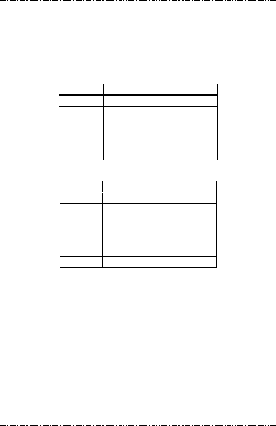
PIN Pad 791 Programmer’s Manual (PCI POS-A) UDN PM0103-U Rev. 06
Section 5 – Administration and maintenance messages 2015-04-20
Page47
Uniform Industrial Corp. Proprietary and Confidential Total 342 pages
Message 14 Enable/Disable Timer Display
Format: <SI>14[E/D]<SO>[LRC] (request frame)
<SI>14[Status]<SO>[LRC] (response frame)
Message length: Fixed 6 bytes.
Usage: This message is used to enable / disable PP791 system timer display.
Message element:
Request frame (HOST to PIN Pad)
Field Length
Value and description
<SI> 1 <0F>
14 2 Message ID
[E/D] 1 ‘0’: Disable
‘1’: Enable
<SO> 1 <0E>
[LRC] 1 Checksum
Response frame (PIN Pad to HOST)
Field Length
Value and description
<SI> 1 <0F>
14 2 Message ID
[Status] 1 ‘0’: Disabled
‘1’: Enabled
‘2’: Format Error
<SO> 1 <0E>
[LRC] 1 Checksum

PIN Pad 791 Programmer’s Manual (PCI POS-A) UDN PM0103-U Rev. 06
Section 5 – Administration and maintenance messages 2015-04-20
Page48
Uniform Industrial Corp. Proprietary and Confidential Total 342 pages
Message flow:
HOST Direction PIN Pad
Message 14
(Request frame)
<ACK> (Good LRC)
<NAK> (Bad LRC)
<EOT> (after 3 NAKs)
Message 14
(Response frame)
<ACK>/<NAK>/<EOT>
<EOT>

PIN Pad 791 Programmer’s Manual (PCI POS-A) UDN PM0103-U Rev. 06
Section 5 – Administration and maintenance messages 2015-04-20
Page49
Uniform Industrial Corp. Proprietary and Confidential Total 342 pages
Message 15 Adjust LCD Backlight Level
Format: <SI>15[contrast stepping code]<SO>[LRC]
Message length: Fixed 6 bytes.
Usage: This message will set the backlight level of LCD monitor.
Message element:
Request frame (HOST to PIN Pad)
Field Length Value and description
<SI> 1 <0F>
15 2 Message ID
[contrast
stepping
code]
1 ASCII character
‘1’ = darkest to
‘8’ = lightest
<SO> 1 <0E>
[LRC] 1 Checksum
Response frame (PIN Pad to HOST)
Field Length
Value and description
<SI> 1 <0F>
15 2 Message ID
[status] 1 ASCII character
‘1’ to ‘8’ for success (echo of contrast
stepping code).
‘F’ for operation fail
<SO> 1 <0E>
[LRC] 1 Checksum
Message flow:
HOST Direction PIN Pad
Message 15 (request)
<ACK> (Good LRC)
<NAK> (Bad LRC)
<EOT> (after 3 NAKs)
Message 15 (response)
<ACK>/<NAK>/<EOT>
<EOT>

PIN Pad 791 Programmer’s Manual (PCI POS-A) UDN PM0103-U Rev. 06
Section 5 – Administration and maintenance messages 2015-04-20
Page50
Uniform Industrial Corp. Proprietary and Confidential Total 342 pages
Message 16 Remote self-test request
Format: <SI>16<SO>[LRC]
Message length: Fixed 5 bytes.
Usage: This message is used to ensure that the PP791 attached to the HOST is working
normally. PP791 will response an ACK (or NAK if LRC incorrect) within one second. If
multiple tests failed, response code will concatenate such as “<SI>16125<SO>”.
Message element:
Request frame (HOST to PIN Pad)
Field Length
Value and description
<SI> 1 <0F>
16 2 Message ID
<SO> 1 <0E>
[LRC] 1 Checksum
Response frame (PIN Pad to HOST)
Field Length
Value and description
<SI> 1 <0F>
16 2 Message ID
[Response] 1 .. 3 0 – Healthy
1 – RAM test fail
2 – ROM checksum fail
5 – Master keys CRC error
<SO> 1 <0E>
[LRC] 1 Checksum
Message flow:
HOST Direction PIN Pad
Message 16
(Request frame)
<ACK> (Good LRC)
<NAK> (Bad LRC)
<EOT> (after 3 NAKs)
Message 16
(Response frame)
<ACK>/<NAK>
/<EOT>
<EOT>

PIN Pad 791 Programmer’s Manual (PCI POS-A) UDN PM0103-U Rev. 06
Section 5 – Administration and maintenance messages 2015-04-20
Page51
Uniform Industrial Corp. Proprietary and Confidential Total 342 pages
Message 17 Request random number
Format: <SI>17<SO>[LRC]
Message length: Fixed 5 bytes.
Usage: This message is used to request PIN Pad to generate an 8bytes random number block.
This random number is generated by hardware TRNG that is certified with sufficient
security.
Message element:
Request frame (HOST to PIN Pad)
Field Length
Value and description
<SI> 1 <0F>
17 2 Message ID
<SO> 1 <0E>
[LRC] 1 Checksum
Response frame (PIN Pad to HOST)
Field Length
Value and description
<SI> 1 <0F>
17 2 Message ID
[RndBlk] 16 Random number block generated
by PP791.
Format: hexadecimal string.
<SO> 1 <0E>
[LRC] 1 Checksum
Message flow:
HOST Direction PIN Pad
Message 17
(Request frame)
<ACK> (Good LRC)
<NAK> (Bad LRC)
<EOT> (after 3 NAKs)
Message 17
(Response frame)
<ACK>/<NAK>
/<EOT>
<EOT>

PIN Pad 791 Programmer’s Manual (PCI POS-A) UDN PM0103-U Rev. 06
Section 5 – Administration and maintenance messages 2015-04-20
Page52
Uniform Industrial Corp. Proprietary and Confidential Total 342 pages
Message 18 Set PIN pad system time
Format: <SI>18[YYYY][MM][DD][W][HH][MM][SS]<SUB>[TZ Variable]<SO>[LRC]
(Request frame for setting local time and time zone)
<SI>18<SUB>[TZ Variable]<SO>[LRC]
(Request frame for setting time zone)
<SI>18[YYYY][MM][DD][W][HH][MM][SS]<SO>[LRC]
(Request frame for setting local time)
Message length: Fixed 20 bytes. Fixed 20 (set date and time only) or Variables (with time zone) bytes.
Usage: This message is used to set PP791 internal clock to display local time and for EMV
level 2 transaction log.
The syntax of time zone environment variables are same as POSIX systems. Please
be aware of the input syntax, otherwise the time zone setting will be invalid. This time
zone setting just needs to setup once, and then the environment variables will be
stored in PP791.
Message element:
Request frame for setting local time and time zone
(HOST to PIN Pad)
Field Length
Value and description
<SI> 1 <0F>
18 2 Message ID
[YYYY] 4 AD year, i.e. “2014”
[MM] 2 Month, “01”~”12”
[DD] 2 Day of month, “01”~”31”
[W] 1 Day of week, “0”=Sunday, ~
“6”=Saturday
[HH] 2 Hour, “00”~”23”
[MM] 2 Minute, “00”~”59”
[SS] 2 Second, “00”~”59”
<SUB> 1 <1A>
[TZ Variable] Var. Time zone environment variable.
(For example,
send
"PST+8PDT,M3.2.0/2,M11.1.0/2"
to set Pacific time zone in the
United States)
<SO> 1 <0E>
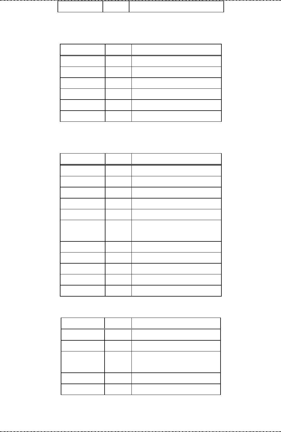
PIN Pad 791 Programmer’s Manual (PCI POS-A) UDN PM0103-U Rev. 06
Section 5 – Administration and maintenance messages 2015-04-20
Page53
Uniform Industrial Corp. Proprietary and Confidential Total 342 pages
[LRC] 1 Checksum
Request frame for setting time zone
(HOST to PIN Pad)
Field Length
Value and description
<SI> 1 <0F>
18 2 Message ID
<SUB> 1 <1A>
[TZ Variable] Var. Time zone environment variable.
<SO> 1 <0E>
[LRC] 1 Checksum
Request frame for setting local time
(HOST to PIN Pad)
Field Length
Value and description
<SI> 1 <0F>
18 2 Message ID
[YYYY] 4 AD year, i.e. “2014”
[MM] 2 Month, “01”~”12”
[DD] 2 Day of month, “01”~”31”
[W] 1 Day of week, “0”=Sunday, ~
“6”=Saturday
[HH] 2 Hour, “00”~”23”
[MM] 2 Minute, “00”~”59”
[SS] 2 Second, “00”~”59”
<SO> 1 <0E>
[LRC] 1 Checksum
Response frame (PIN Pad to HOST)
Field Length
Value and description
<SI> 1 <0F>
18 2 Message ID
[status] 1 0: Success
F: Failed.
<SO> 1 <0E>
[LRC] 1 Checksum

PIN Pad 791 Programmer’s Manual (PCI POS-A) UDN PM0103-U Rev. 06
Section 5 – Administration and maintenance messages 2015-04-20
Page54
Uniform Industrial Corp. Proprietary and Confidential Total 342 pages
Message flow:
HOST Direction PIN Pad
Message 18 request frame
<ACK> (Good LRC)
<NAK> (Bad LRC)
<EOT> (after 3 NAKs)
Message 18 Response Frame
<ACK> /<NAK> /<EOT>
Processing and send <EOT>
NOTE:
The followings describe that how to input a proper syntax of time zone enviorment variable.
The first format is used when there is no Daylight Saving Time in the local time zone:
std offset
The std string specifies the name of the time zone. It must be 3 ~ 6 characters long and must not contain a
leading colon, embedded digits, commas nor plus and minus signs.
The offset specifies the time value you must add to the local time to get a Coordinated Universal Time
value. It has syntax like [+|-]hh[:mm[:ss]]. This is positive if the local time zone is west of the Prime Meridian
and negative if it is east. The hour must be between 0 and 23, and the minute and seconds between 0 and
59. (for example, PST+8)
The second format is used when there is Daylight Saving Time:
std offset dst[offset],start[/time],end[/time]
The initial std and offset specify the standard time zone, as described above. The dst string and offset
specify the name and offset for the corresponding Daylight Saving Time zone. If the offset is omitted, it
defaults to one hour ahead of standard time.
The start field is when Daylight Saving Time goes into effect and the end field is when the change is made
back to standard time. The following formats are recognized for these fields:
Jn
This specifies the Julian day, with n between 1 and 365. February 29 is never counted, even in
leap years.
n
This specifies the Julian day, with n between 0 and 365. February 29 is counted in leap years.

PIN Pad 791 Programmer’s Manual (PCI POS-A) UDN PM0103-U Rev. 06
Section 5 – Administration and maintenance messages 2015-04-20
Page55
Uniform Industrial Corp. Proprietary and Confidential Total 342 pages
Mm.w.d This specifies day d of week w of month m. The day d must be between 0 (Sunday) and 6. The
week w must be between 1 and 5, week 1 is the first week in which day d occurs, and week 5
specifies the last d day in the month. The month m should be between 1 and 12.
The time fields specify when, in the local time currently in effect, the change to the other time occurs. If
omitted, the default is 02:00:00.
For example, here is how you would specify the Pacific time zone in the United States, including the
appropriate Daylight Saving Time and its dates of applicability. The normal offset from UTC is 8 hours, since
this is west of the prime meridian, the sign is positive. Summer time begins on the second Sunday in March at
2:00am, and ends on the first Sunday in Novenber at 2:00am.
PST+8PDT,M3.2.0/2,M11.1.0/2
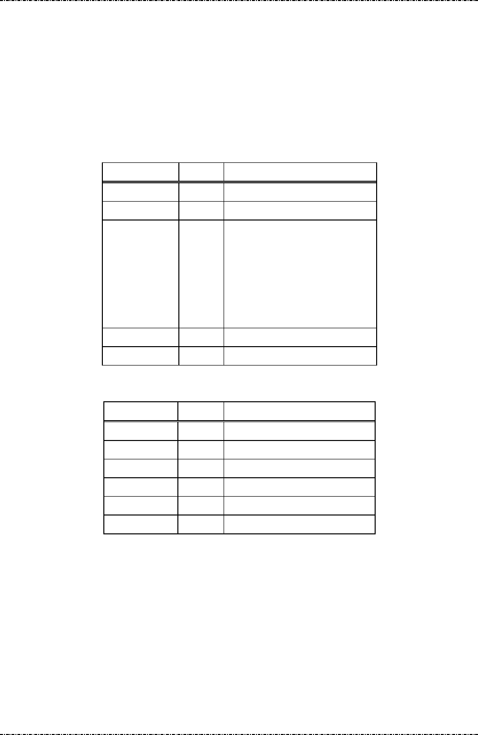
PIN Pad 791 Programmer’s Manual (PCI POS-A) UDN PM0103-U Rev. 06
Section 5 – Administration and maintenance messages 2015-04-20
Page56
Uniform Industrial Corp. Proprietary and Confidential Total 342 pages
Message 19 Query Firmware Version
Format: <SI>19[part]<SO>[LRC] (request frame)
<SI>19.[Version] <SO>[LRC] (response frame)
Message length: Fixed 6 bytes (request frame) / Variable (response frame).
Usage: This message is used to query PP791 firmware version number and firmware check
sum value.
Message element:
Request frame (HOST to PIN Pad)
Field Length
Value and description
<SI> 1 <0F>
19 2 Message ID
[part] 1 Firmware Part number
1: Uboot
2: Kernel
3: Root File System (RFS)
4: System Manager (SysMgr)
5: PP791 App.
<SO> 1 <0E>
[LRC] 1 Checksum
Response frame (PIN Pad to HOST)
Field Length
Value and description
<SI> 1 <0F>
19 2 Message ID
. 1 <2E>, field separator
[Version] Var. Version string (ASCII string)
<SO> 1 <0E>
[LRC] 1 Checksum

PIN Pad 791 Programmer’s Manual (PCI POS-A) UDN PM0103-U Rev. 06
Section 5 – Administration and maintenance messages 2015-04-20
Page57
Uniform Industrial Corp. Proprietary and Confidential Total 342 pages
Message flow:
HOST Direction PIN Pad
Message 19
(Request frame)
<ACK> (Good LRC)
<NAK> (Bad LRC)
<EOT> (after 3 NAKs)
Message 19
(Response frame)
<ACK>/<NAK>/<EOT>
<EOT>
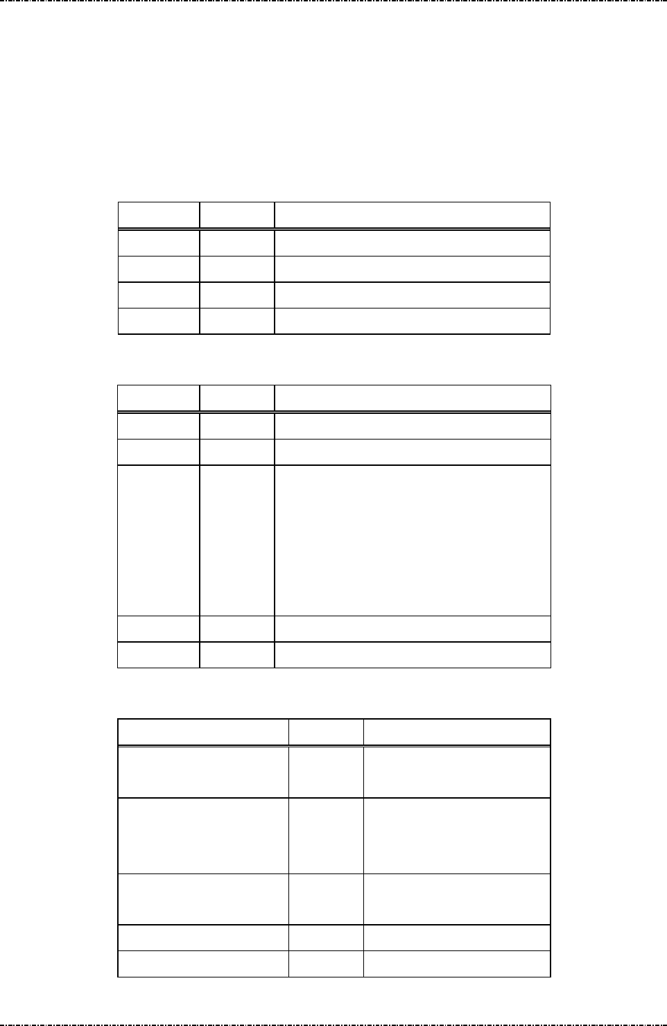
PIN Pad 791 Programmer’s Manual (PCI POS-A) UDN PM0103-U Rev. 06
Section 5 – Administration and maintenance messages 2015-04-20
Page58
Uniform Industrial Corp. Proprietary and Confidential Total 342 pages
Message 1C Query Hardware Capability
Format: <SI>1C<SO>[LRC] (request frame)
<SI>1C[string]<SO>[LRC] (response frame)
Message length: Fixed 5 bytes (request). Variable (response).
Usage: This message is used to query the peripheral capability of PP791.
Message element:
Request frame (HOST to PIN Pad)
Field Length Value and description
<SI> 1 <0F>
1C 2 Message ID
<SO> 1 <0E>
[LRC] 1 Checksum
Response frame (PIN Pad to HOST)
Field Length Value and description
<SI> 1 <0F>
1C 2 Message ID
[string] Variable <1C>[HW1]<1C>[HW2]......
Possible string:
“ICC”: Smart card reader.
“SAM”: Security Access Module Slot.
“MSR”: Magnetic Stripe Reader.
“0” Pure PIN pad without peripherals.
<SO> 1 <0E>
[LRC] 1 Checksum
Message flow:
HOST Direction PIN Pad
Message 1C
(Request frame)
<ACK> (Good LRC)
<NAK> (Bad LRC)
<EOT> (after 3 NAKs)
Message 1C
(Response frame)
<ACK>/<NAK>/<EOT>
<EOT>

PIN Pad 791 Programmer’s Manual (PCI POS-A) UDN PM0103-U Rev. 06
Section 5 – Administration and maintenance messages 2015-04-20
Page59
Uniform Industrial Corp. Proprietary and Confidential Total 342 pages
Message 1F Query Usable Prompt Table
Format: <SI>1F<SO>[LRC] (request frame)
<SI>1F[Prompt_List]<SO>[LRC] (response frame)
Message length: Fixed 6 bytes (request frame); Variable (response frame).
Usage: This message is used to query usable PP791 prompt message table list. List will be
represented as 2-character country code defined by ISO 3166.
Message element:
Request frame (HOST to PIN Pad)
Field Length
Value and description
<SI> 1 <0F>
1F 2 Message ID
<SO> 1 <0E>
[LRC] 1 Checksum
Response frame (PIN Pad to HOST)
Field Length
Value and description
<SI> 1 <0F>
1F 2 Message ID
[Prompt List] 20 Format:
[active country code]
<FS> [country code0]
….
<FS> [country code5]
<SO> 1 <0E>
[LRC] 1 Checksum
Message flow:
HOST Direction PIN Pad
Message 1F
(Request frame)
<ACK> (Good LRC)
<NAK> (Bad LRC)
<EOT> (after 3 NAKs)
Message 1F
(Response frame)
<ACK>/<NAK>/<EOT>

PIN Pad 791 Programmer’s Manual (PCI POS-A) UDN PM0103-U Rev. 06
Section 5 – Administration and maintenance messages 2015-04-20
Page60
Uniform Industrial Corp. Proprietary and Confidential Total 342 pages
<EOT>
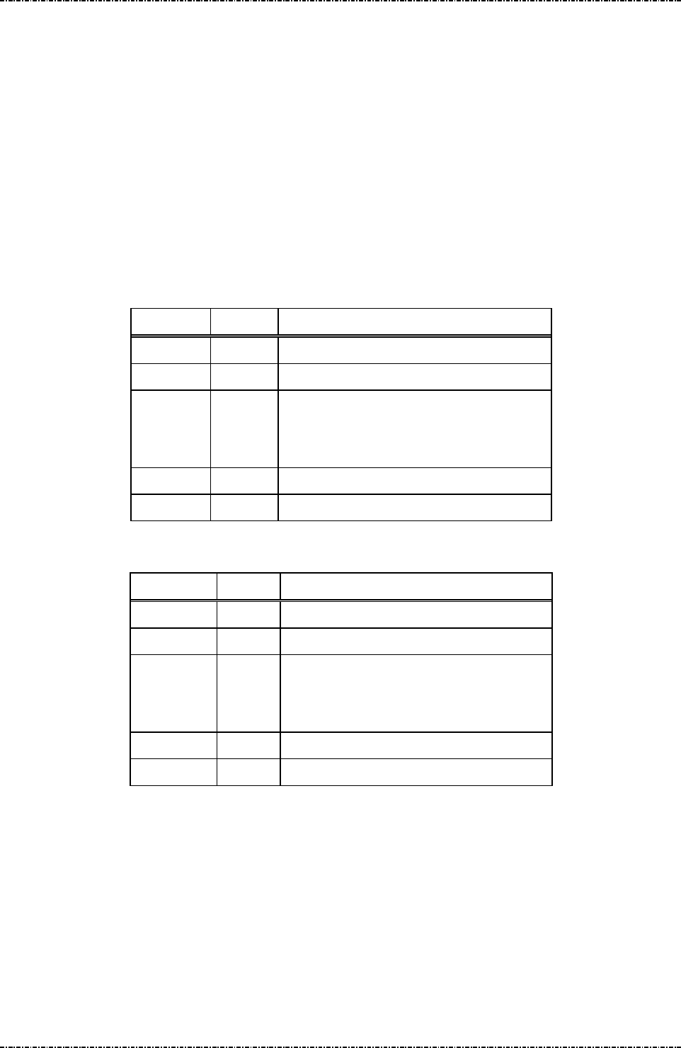
PIN Pad 791 Programmer’s Manual (PCI POS-A) UDN PM0103-U Rev. 06
Section 5 – Administration and maintenance messages 2015-04-20
Page61
Uniform Industrial Corp. Proprietary and Confidential Total 342 pages
Message 1J Turn ON/OFF LCD Backlight
Format: <SI>1J[option]<SO>[LRC]
Message length: Fixed 6 bytes.
Usage: This message can control the global backlight ON or OFF for the LCD of PP791 with
backlight option. By default, PP791 will turn on its LCD backlight when it receives PIN
entry or clear text entry message such as 70 or Z50, and turn it off when those
functions exits. With message “1J1”, the PP791 will keep LCD backlight turned ON
until “1J0” is issued.
Message element:
Request frame (HOST to PIN Pad)
Field Length
Value and description
<SI> 1 <0F>
1J 2 Message ID
[option] 1 ASCII character
‘0’: Turn off LCD backlight
‘1’: Turn on LCD backlight
<SO> 1 <0E>
[LRC] 1 Checksum
Response frame (PIN Pad to HOST)
Field Length
Value and description
<SI> 1 <0F>
1J 2 Message ID
[status] 1 ASCII character
‘0’: Turn off LCD backlight
‘1’: Turn on LCD backlight
<SO> 1 <0E>
[LRC] 1 Checksum

PIN Pad 791 Programmer’s Manual (PCI POS-A) UDN PM0103-U Rev. 06
Section 5 – Administration and maintenance messages 2015-04-20
Page62
Uniform Industrial Corp. Proprietary and Confidential Total 342 pages
Message flow:
HOST Direction PIN Pad
Message 1J
<ACK> (Good LRC)
<NAK> (Bad LRC)
<EOT> (after 3 NAKs)
Message 1J
(Response frame)
<ACK>/
<NAK>/
<EOT>
<EOT>
LCD backlight turned ON/OFF
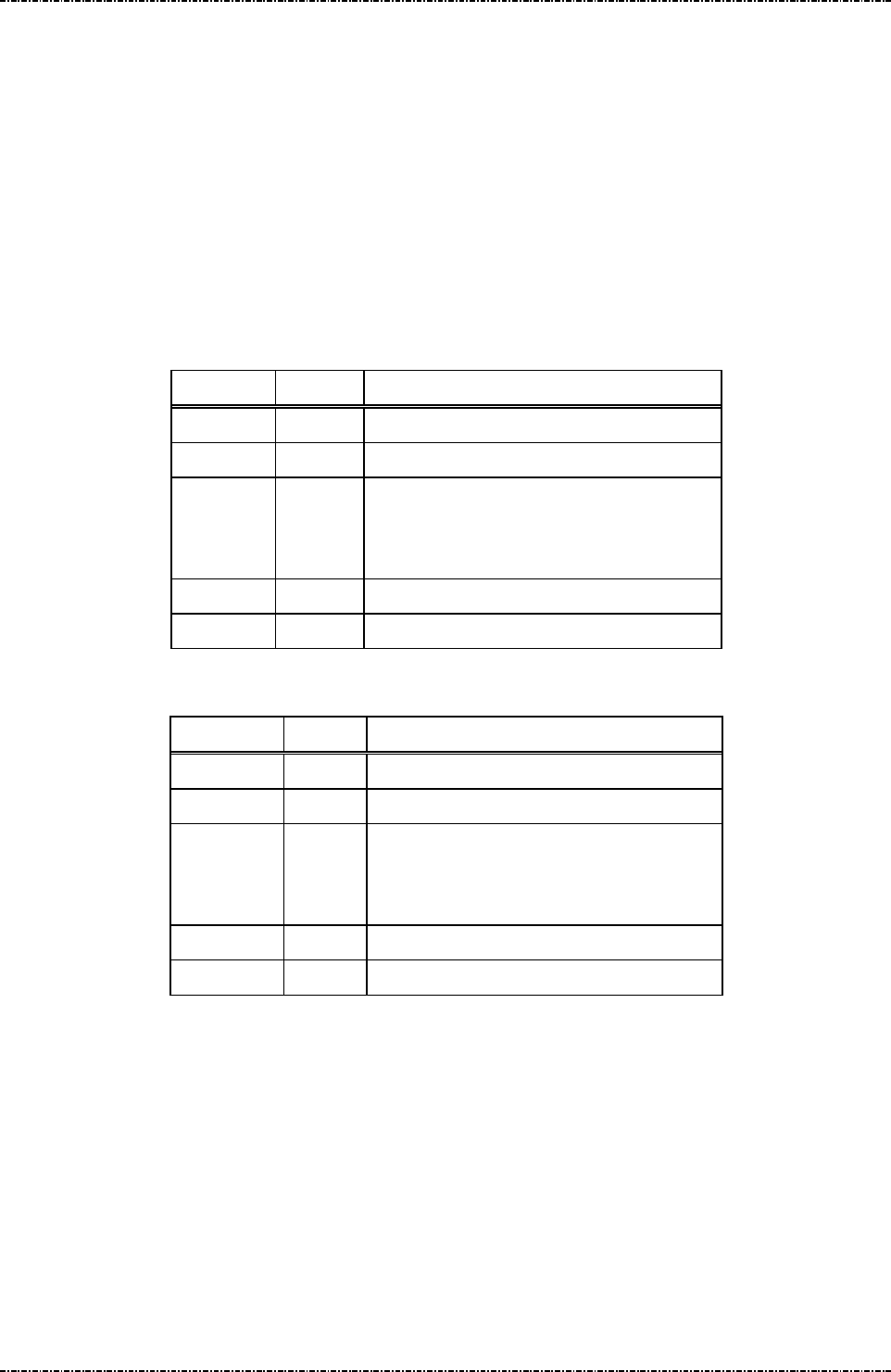
PIN Pad 791 Programmer’s Manual (PCI POS-A) UDN PM0103-U Rev. 06
Section 5 – Administration and maintenance messages 2015-04-20
Page63
Uniform Industrial Corp. Proprietary and Confidential Total 342 pages
Message 1KTurn ON/OFF LCD Power-save mode
Format: <SI>1K[option]<SO>[LRC]
Message length: Fixed 6 bytes.
Usage: For power consumption saving, this message can make PP791 turns the backlight
level to darker after several seconds automatically. The backlight level will return to the
value set before when a key strobe is pressed, a message about PIN entry or key entry
is received.
Message element:
Request frame (HOST to PIN Pad)
Field Length
Value and description
<SI> 1 <0F>
1K 2 Message ID
[option] 1 ASCII character
‘0’: Turn off LCD power-save mode
‘1’: Turn on LCD power-save mode
<SO> 1 <0E>
[LRC] 1 Checksum
Response frame (PIN Pad to HOST)
Field Length
Value and description
<SI> 1 <0F>
1K 2 Message ID
[status] 1 ASCII character
‘0’: Turn off LCD power-save mode
‘1’: Turn on LCD power-save mode
<SO> 1 <0E>
[LRC] 1 Checksum

PIN Pad 791 Programmer’s Manual (PCI POS-A) UDN PM0103-U Rev. 06
Section 5 – Administration and maintenance messages 2015-04-20
Page64
Uniform Industrial Corp. Proprietary and Confidential Total 342 pages
Message flow:
HOST Direction PIN Pad
Message 1K
<ACK> (Good LRC)
<NAK> (Bad LRC)
<EOT> (after 3 NAKs)
Message 1K
(Response frame)
<ACK>/
<NAK>/
<EOT>
<EOT>
LCD power-save mode turned ON/OFF
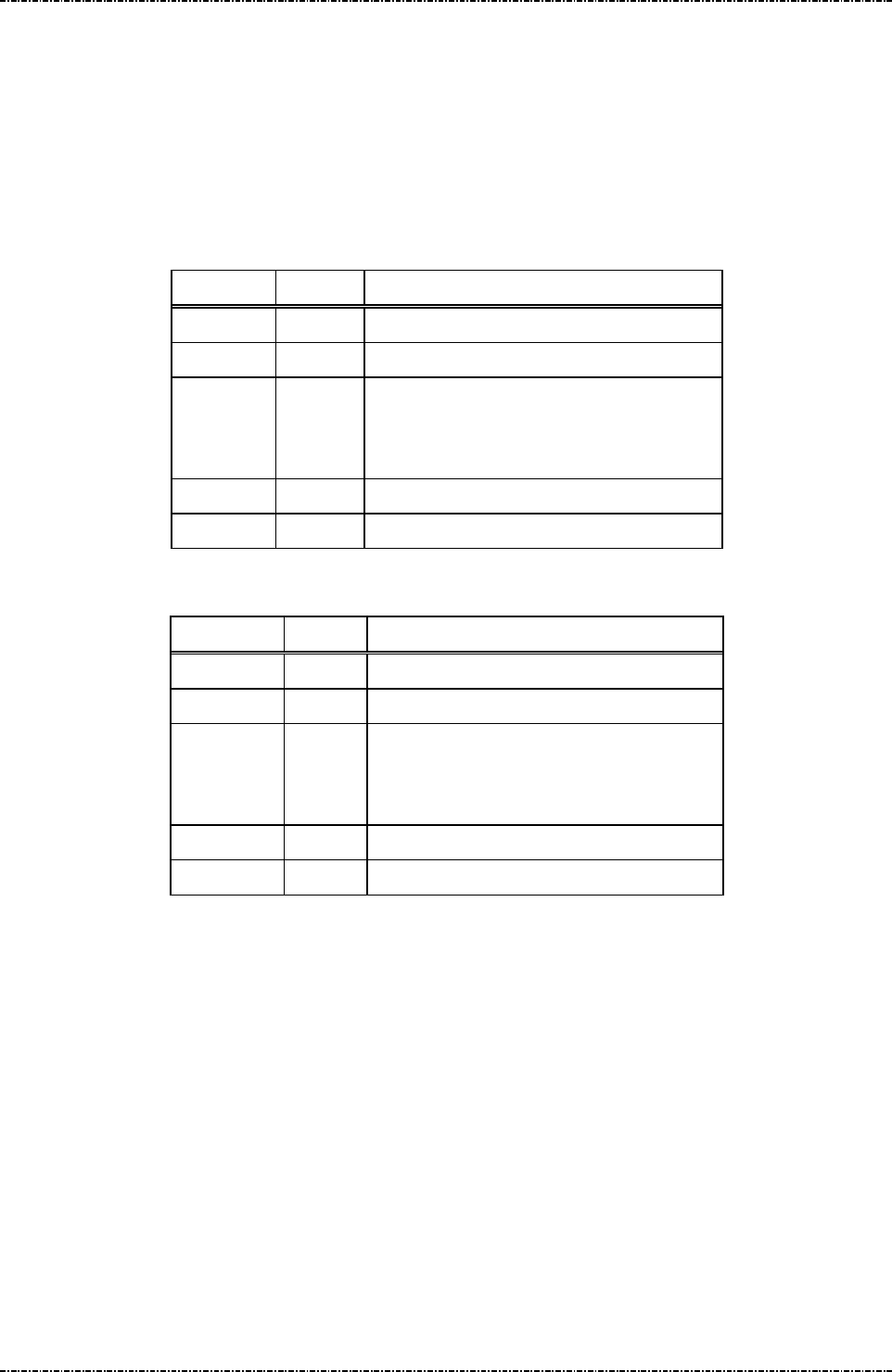
PIN Pad 791 Programmer’s Manual (PCI POS-A) UDN PM0103-U Rev. 06
Section 5 – Administration and maintenance messages 2015-04-20
Page65
Uniform Industrial Corp. Proprietary and Confidential Total 342 pages
Message 1M Setup Keypad Beeper
Format: <SI>1M[option]<SO>[LRC]
Message length: Fixed 6 bytes.
Usage: This message is used to turn on or turn off beeper when the keypad is pressing.
Message element:
Request frame (HOST to PIN Pad)
Field Length
Value and description
<SI> 1 <0F>
1M 2 Message ID
[option] 1 ASCII character
‘0’: Disable keypad beeper.
‘1’: Enable keypad beeper.
<SO> 1 <0E>
[LRC] 1 Checksum
Response frame (PIN Pad to HOST)
Field Length
Value and description
<SI> 1 <0F>
1M 2 Message ID
[status] 1 ASCII character
‘0’: Keypad beeper disabled.
‘1’: Keypad beeper enabled.
<SO> 1 <0E>
[LRC] 1 Checksum

PIN Pad 791 Programmer’s Manual (PCI POS-A) UDN PM0103-U Rev. 06
Section 5 – Administration and maintenance messages 2015-04-20
Page66
Uniform Industrial Corp. Proprietary and Confidential Total 342 pages
Message flow:
HOST Direction PIN Pad
Message 1M
<ACK> (Good LRC)
<NAK> (Bad LRC)
<EOT> (after 3 NAKs)
Message 1M
(Response frame)
<ACK>/
<NAK>/
<EOT>
<EOT>

PIN Pad 791 Programmer’s Manual (PCI POS-A) UDN PM0103-U Rev. 06
Section 6 – Contact EMV Level 2 transaction messages 2015-04-20
Page67
Uniform Industrial Corp. Proprietary and Confidential Total 342 pages
Section 6 Contact EMV Level 2 transaction messages
EMV Level2 transaction messages are divided into 2 groups. One is EMV-configuration data operation
messages (T01, T03, T05, T07, T09, T0B) and the other one is EMV-transaction messages (T11, T13, T15,
T17, T19, T1C, T21, T25, T27, T29).
The ICC EMV transaction messages issuing sequence is control by PIN pad, an invalid sequence will
terminate ICC EMV transaction. At the first of ICC EMV transaction, user has to issue messages T11 to make
PIN pad negotiate with card and generate a candidate list of EMV-application that supported by PIN pad and
card both, and then select a highest priority one automatically or selected by user (according to the terminal
configuration data installed in PIN pad), finally return the EMV-application name. Message T15 is used for
terminal-side to transmit transaction information such as amount and then PIN pad do a complete transaction
with card if the transaction needs not to be authorized online. Terminal can issue message T1D to transmit
additional transaction data into PIN pad for ICC EMV transaction, such as online response data, magnetic
stripe card track data. Message T17 is applied if the transaction needs to be authorized online, terminal-side
will transmit necessary information via this message to PIN pad to continue the rest steps of transaction. If
the response from host contains issuer script (see EMV), terminal-side applies message T19 to input these
scripts into PIN pad and PIN pad will issue these scripts at appropriate time to card. Message T1C is used to
terminate an ICC EMV transaction. Finally, message T21 is used for terminal-side to get the transaction
information through EMV transaction.
Terminal can apply Txx messages to handle a complete ICC EMV transaction except that the transaction
must be changed to magnetic stripe card processing. According to EMV rule, if terminal fails to read IC card,
the transaction could be change to magnetic stripe card transaction. Because of different types of magnetic
stripe card, the magnetic stripe card processing should be taken by terminal. Terminal could issue message
Q1 provided by PIN pad to make user swipe his card and then issue message 70 to complete a magnetic
stripe card transaction. In this situation, terminal will get response of T11 message that indicates an failed IC
card read, terminal should then issue message T1D, T15 and T17 to PIN pad for batch data capture. The flow
chart for changing to magnetic stripe card processing could be referred in “Overall Contact EMV level 2
transaction flow reference” section.

PIN Pad 791 Programmer’s Manual (PCI POS-A) UDN PM0103-U Rev. 06
Section 6 – Contact EMV Level 2 transaction messages 2015-04-20
Page68
Uniform Industrial Corp. Proprietary and Confidential Total 342 pages
The meaning of error code in the [Err Message] are listed below:
Error Code Error Description
00000003 Service not accepted.
00000F9B Store configuration data error.
8FFF0001 Out of memory.
8FFF0002 Parameter error.
8FFFFF02 Tag’s data format error.
8FFFFF03 Some mandatory tags are not configured well.
8FFFFFF0 Command format error.
8FFFFFF1 The sequence of EMV transaction command is error.
8FFFFFF2 Terminal fundamental data is missing.
8FFFFFF3 Authentication failed.
8FFFFF1A Authentication key expired.
8FFFFF1B Terminal configuration data is missing.
8FFFFF1C No configuration data of EMV application or the data is missing.
8FFFFFF4 The storage space of batch data capture is full.
8FFFFFF5 No terminal configuration data, EMV application configuration data or CA public key.
A2000001 Application initial conditions are not satisfied.
A2000002 The generated cryptogram is not allowed.
A2000007 The instruction ID of the specified is not recognized.
A200000A The type to request application cryptogram is incorrect.
A200000C The status response (SW1 SW2) is other than ‘9000’.
A200000D The Generate AC command is called more than 2 times in the current transaction.
A200000E The AIP mandatory data is missing in response data from card.
A200000F The AFL mandatory data is missing in response data from card.
A2000010 The response template from card isn't correct.
A2000011 The format of AFL is incorrect.
A2000013 A redundant data output from card is not allowed.
A2000014 Missing mandatory data in response data from card.
EFFFFFFF EMV transaction cancelled.
DFFFFFFF EMV forced abort.
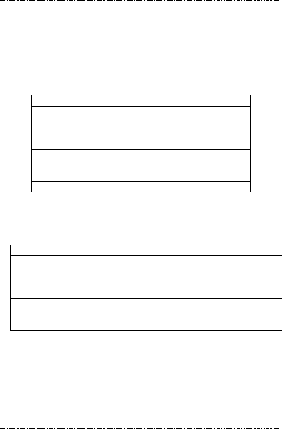
PIN Pad 791 Programmer’s Manual (PCI POS-A) UDN PM0103-U Rev. 06
Section 6 – Contact EMV Level 2 transaction messages 2015-04-20
Page69
Uniform Industrial Corp. Proprietary and Confidential Total 342 pages
Message T01 Terminal Configuration Setup
Format: <STX>T01[Pkt No.][Total Pkts]<SUB>[DO]<ETX>[LRC]
Message length: Variable.
Usage: Host can use this command to send terminal configuration data to PIN pad, this
command can be sent many times. PIN pad will save those data inside and apply
those data when do the transaction. PIN pad will send the message T02 (Terminal
Configuration Setup Response) to host.
Message element:
Field Length
Value and description
<STX> 1 <02>
T01 3 Message ID
Pkt No. 1 Decimal. Packet sequence number (1 ~ 9)(ex. 2)
Total Pkts 1 Decimal. Total packets (1~9)(ex. 8).
<SUB> 1 <1A, Optional, only if [DO] is existed
DO Var. Data Object, format as below
<ETX> 1 <03>
[LRC] 1 Checksum
Data Object Format: each data object is delimited by <SUB>, and each field inside each data
object is delimited by <FS>.
Data Format: (Please also refer to EMV 4.3 BOOK3, section 4.3)
Format
Description
1 a - Alphabetic data (a ~z, A~Z)
2 b - unsigned binary numbers or bit combinations
3 an - Alphanumeric data (a ~z, A~Z, 0~9)
4 ans - Alphanumeric Special data (Characters defined in ISO8859)
5 cn - Compressed numeric data (0~9, left justify, pad hexadecimal ‘F’s. Ex. 12 34 56 12 3F FF)
6 n - Numeric data (0~9, right justify, pad leading hexadecimal zeroes. Ex. 00 00 00 01 23 45)
7 var - Variable data (Any bit combination)
Note. User has to obey the restriction specified in EMV 4.3 BOOK3, Annex A and Appendix D of
this document to load configuration data. PIN pad will check if the length of each
configuration data item is consistent. Any inconsistent data item will make data loading
fail.
Note. If the data format is ‘2’ (binary), ‘5’(compressed numeric), ‘6’(numeric) or ‘7’(variable data),
it can not be allocated in message T01 directly. It should be transferred into hexadecimal
string and then allocated in message T01.

PIN Pad 791 Programmer’s Manual (PCI POS-A) UDN PM0103-U Rev. 06
Section 6 – Contact EMV Level 2 transaction messages 2015-04-20
Page70
Uniform Industrial Corp. Proprietary and Confidential Total 342 pages
Example: (Clear the terminal configuration data and then setup new data.)
Merchant Category Code: 0000 (Numerical)
Terminal ID: SmartPOS (Ascii)
UI Capability: 0x01 (binary)
<STX>T0111<SUB>9f15<FS>6<FS>0000<SUB>9f1c<FS>3<FS>SmartPOS<SUB>
50000002<FS>2<FS>01<ETX>[LRC]
Special Tag for PIN pad: 0x50000001, 0x50000002
Name Description Format Tag Length
Terminal UI
Capability
0: Make PIN pad selects the highest
priority application and ask user’s
confirmation.
1:Make PIN pad provides a list of
candidate applications.
b 50000002 1
MSR
Processing
Batch Tag
List
PIN pad will store transaction data
according to the tag list while the
transaction is performed as MSR
processing. Ex, for tag list (829F365F3
09F399F029F03), PIN pad will store
transaction data of tag number 0x82,
0x9F36, 0x5F30, 0x9F39, 0x9F02 and
0x9F03.
b 50000003 var
Online PIN
Block Tag
Define
User can define new tag number for
online PIN block.
b 50000004 1~4
Online PIN
Key Tag
Define
User can define new tag number for
online PIN key.
b 50000005 1~4
These data object are defined in EMV 4.3 BOOK3, Annex A without tag values. The tag values are
defined by UIC.
NOTE.
In order to make PIN pad accept new defined tag (Online PIN Block Tag, Online PIN Key Tag),
terminal should issue message T07 to add the new tag into tag table inside PIN pad. For example, if
terminal wants to define new tag 0xDF01 and 0xDF02 for PIN block tag and PIN key tag, it must
issue message T07 with value “0<SUB>DF01<FS>202020<SUB>DF02<FS>202020” to add new tag
number into tag table inside PIN pad. Finally, issue message T01 with value “50000004
<FS>2<FS>DF01<SUB>50000005<FS>2<FS>DF02”

PIN Pad 791 Programmer’s Manual (PCI POS-A) UDN PM0103-U Rev. 06
Section 6 – Contact EMV Level 2 transaction messages 2015-04-20
Page71
Uniform Industrial Corp. Proprietary and Confidential Total 342 pages
PIN pad will check if terminal downloads minimum set of terminal-related information into PIN
pad. The download process will be failed if there is not enough data in this message. Please
refer to Appendix E for minimum set of terminal-related data
Message flow:
HOST Direction PIN pad
1st Message T01
<ACK> (Good LRC)
<NAK> (Bad LRC)
<EOT> (after 3 NAKs)
1st Message T02
<ACK> (Good LRC)
<NAK> (Bad LRC)
<EOT> (after 3 NAKs)
2nd Message T01
<ACK> (Good LRC)
<NAK> (Bad LRC)
<EOT> (after 3 NAKs)
2nd Message T02
<ACK> (Good LRC)
<NAK> (Bad LRC)
<EOT> (after 3 NAKs)
… … …
Last one Message T01
<ACK> (Good LRC)
<NAK> (Bad LRC)
<EOT> (after 3 NAKs)
Last one Message T02
<ACK> (Good LRC)
<NAK> (Bad LRC)
<EOT> (after 3 NAKs)

PIN Pad 791 Programmer’s Manual (PCI POS-A) UDN PM0103-U Rev. 06
Section 6 – Contact EMV Level 2 transaction messages 2015-04-20
Page72
Uniform Industrial Corp. Proprietary and Confidential Total 342 pages
Message T02 Terminal Configuration Setup Response
Format: <STX>T02[Res][Reason][Err Msg][Err Tag Number]<ETX>[LRC]
Message length: Variable.
Usage: The response message of command T01.
Message element:
Field Length Value and description
<STX> 1 <02>
T02 3 Message ID
Res 1 ‘0’: Ok,
‘1’: Fail
Reason 1 <Optional, if Res = ‘1’>
‘1’: Fatal Error
‘2’: Format Error
‘3’: Invalid Data Object format.
‘4’: Invalid Tag value
Err Message 8 Optional, if Reason = ‘1’, Hex decimal string
Err Tag Number Var. Optional, if Reason = ‘3’ or ‘4’, Hex decimal
string
<ETX> 1 <03>
[LRC] 1 Checksum
Message flow: Please refer to message T01.

PIN Pad 791 Programmer’s Manual (PCI POS-A) UDN PM0103-U Rev. 06
Section 6 – Contact EMV Level 2 transaction messages 2015-04-20
Page73
Uniform Industrial Corp. Proprietary and Confidential Total 342 pages
Message T03 Certification Authority Public Key Setup
Format: <STX>T03[Op code][RID][PKI][Hash Algo][Hash][PK Algo][PK Leng]
[PK Exponent]<ETX>[LRC]
<STX>T03[Op code][PK Modulus]<ETX>
Message length: Variable.
Usage: Host can use this command to send the Certification Authority Public key data to
PIN pad, each command can only setup one key but this command can be sent many
times. PIN pad will save those key data inside and use those data when do the
transaction. PIN pad will send the message T04 (Certification Authority Public Key
Setup Response) to host. The data installed into PIN pad via this message, PIN pad
will save it in internal storage structure with a name same as concatenation of value in
[RID] and [PKI] fields. Ex. value in [RID] field is “A000000003”, value in [PKI] filed is
“90”, PIN pad will save these data and give an ID as “A00000000390”.
Message element:
1st Packet (Load RSA public key):
Field Length
Value and description
<STX> 1 <02>
T03 3 Message ID
Op code 1 1: Load first part of RSA public key
RID 10 Hexadecimal string, the left 5 bytes of Registered
Application Provider ID
PKI 2 Public Key Index, hexadecimal string. (Refer to
EMV 4.3, tag ‘9F22’)
Hash
Algorithm
2 Hash Algorithm Index, hexadecimal string
‘01’: SHA-1. Now, PIN pad accepts only ‘01’.
Hash 40 Hash checksum, hexadecimal
Sha1(PKModules)
or
Sha1(RID+PKI+PKModules+PKExp)
PK
Algorithm
2 Public Key Algorithm, hexadecimal string
‘01’: RSA digital signature. Now, PIN pad accepts
only ‘01’.
PK Leng 2 Public Key size, hexadecimalstring, for example:
‘80’ = 128 bytes = 1024 bits
PK
Exponent
1 Public Key Exponent’s size, hexadecimal
‘1’: 3
‘2’: 216+1

PIN Pad 791 Programmer’s Manual (PCI POS-A) UDN PM0103-U Rev. 06
Section 6 – Contact EMV Level 2 transaction messages 2015-04-20
Page74
Uniform Industrial Corp. Proprietary and Confidential Total 342 pages
<ETX> 1 <03>
[LRC] 1 Checksum
2nd Packet (Load RSA public key):
Field Length Value and description
<STX> 1 <02>
T03 3 Message ID
Op code 1 2: Load second part of RSA public key
PK
Modulus
Var Public Key Modulus, presented in
hexadecimal, data length = 2*[PK length]
<ETX> 1 <03>
[LRC] 1 Checksum
Message flow:
HOST Direction PIN pad
1st Message T03
<ACK> (Good LRC)
<NAK> (Bad LRC)
<EOT> (after 3 NAKs)
1st CA Public Key Setup
Response Message T04
<ACK> (Good LRC)
<NAK> (Bad LRC)
<EOT> (after 3 NAKs)
2nd Message T03
<ACK> (Good LRC)
<NAK> (Bad LRC)
<EOT> (after 3 NAKs)
2nd CA Public Key Setup
Response Message T04
<ACK> (Good LRC)
<NAK> (Bad LRC)
<EOT> (after 3 NAKs)

PIN Pad 791 Programmer’s Manual (PCI POS-A) UDN PM0103-U Rev. 06
Section 6 – Contact EMV Level 2 transaction messages 2015-04-20
Page75
Uniform Industrial Corp. Proprietary and Confidential Total 342 pages
Message T04 Certification Authority Public Key Setup Response
Format: <STX>T04[Sequence][Res][Reason][Err Msg]<ETX>[LRC]
Message length: Variable.
Usage: The response message of command T03.
Message element:
1st, 2nd Packet:
Field Length Value and description
<STX> 1 <02>
T04 3 Message ID
Sequence 1 1 / 2 (first/second part of RSA public key)
Res 1 ‘0’: Ok,
‘1’: Fail
Reason 1 ‘1’: Fatal Error
‘2’: Format Error
‘3’: Authentication Fail
Err Message 8 Optional, if Reason = ‘1’Hex String
<ETX> 1 <03>
[LRC] 1 Checksum
Message flow: Please refer to message T03.

PIN Pad 791 Programmer’s Manual (PCI POS-A) UDN PM0103-U Rev. 06
Section 6 – Contact EMV Level 2 transaction messages 2015-04-20
Page76
Uniform Industrial Corp. Proprietary and Confidential Total 342 pages
Message T05 EMV Application Configuration Setup
Format: <STX>T05[Pkt No.][Total Pkts]<SUB>[AID]<SUB>[DO]<ETX>[LRC]
<STX>T05[Pkt No.][Total Pkts]<SUB>[DO]<ETX>[LRC]
Message length: Variable.
Usage: Host can use this command to send the EMV application configuration data to PIN
pad, this command can be sent many times but each command is only for one
application. PIN pad will save those data inside and use those data when do the
transaction. PIN pad will send the message T06 (EMV Application Configuration Setup
Response) to host. The data installed into PIN pad via this message, PIN pad will save
it in internal storage structure with a name same as in [AID] field.
Message element:
1st Message:
Field Length
Value and description
<STX> 1 <02>
T05 3 Message ID
Pkt No. 1 Decimal. Packet sequence number (1 ~ 9)
Total Pkts 1 Decimal. Total packets (1~9)(ex. 8).
<SUB> 1 Optional, if Pkt No is 1 <1A>
AID 10~32
Optional, if Pkt No is 1. EMV Application ID, refer to EMV 4.3
<SUB> 1 Optional, only if [DO] is existed
DO Var. Data Object, format as below
<ETX> 1 <03>
[LRC] 1 Checksum
Rest of Message (If there are 2 more messages):
Field Length
Value and description
<STX> 1 <02>
T05 3 Message ID
Pkt No. 1 Decimal. Packet sequence number (1 ~ 9)
Total Pkts 1 Decimal. Total packets (1~9)(ex. 8).
<SUB> 1 Optional, only if [DO] is existed
DO Var. Data Object, format as below
<ETX> 1 <03>
[LRC] 1 Checksum

PIN Pad 791 Programmer’s Manual (PCI POS-A) UDN PM0103-U Rev. 06
Section 6 – Contact EMV Level 2 transaction messages 2015-04-20
Page77
Uniform Industrial Corp. Proprietary and Confidential Total 342 pages
Data Format: (Please also refer to EMV 4.3 BOOK3, section 4.3)
Format
Description
1 a - Alphabetic data (a ~z, A~Z)
2 b - unsigned binary numbers or bit combinations
3 an - Alphanumeric data (a ~z, A~Z, 0~9)
4 ans - Alphanumeric Special data (Characters defined in ISO8859)
5 cn - Compressed numeric data (0~9, left justify, pad hexadecimal ‘F’s. Ex. 12 34 56 12 3F FF)
6 n - Numeric data (0~9, right justify, pad leading hexadecimal zeroes. Ex. 00 00 00 01 23 45)
7 var - Variable data (Any bit combination)
Note. User has to obey the restriction specified in EMV 4.3 BOOK3, Annex A and Appendix D of
this document to load configuration data. PIN pad will check if the length of each
configuration data item is consistent. Any inconsistent data item will make data loading
fail.
Note. If the data format is ‘2’ (binary), ‘5’(compressed numeric), ‘6’(numeric) or ‘7’(variable data),
it can not be allocated in message T05 directly. It should be transfer into hexadecimal
string and then allocated in message T05.
Example:
Default TDOL: 97 07 9f 02 06 95 05 9b 02 (binary)
Threshold Value for Biased Random Selection: 00 00 00 00 40 00(numerical)
Max. Target percentage to be used for Biased Random selection: 100 (decimal) / 0x46 (binary)
<STX>T0511<SUB>A00000031010<SUB>97<FS>2<FS>97079f020695059b02
<SUB>40000004<FS>6<FS>000000004000 <SUB>40000006<FS>2<FS>46<ETX>[LRC]
PIN pad saves these data and give an ID as “A00000031010” to this group of data.
Special Tag for PIN pad: 0x40000001, 0x40000004, 0x40000005, 0x40000006, 0x40000007,
0x40000008, 0x40000009.
Name Description Format Tag Length
Application Selection Indicator See below n 40000001 1
Threshold Value for Biased
Random Selection
See below n 40000004 6
Target Percentage to be used
for Biased Random Selection
See below b 40000005 1
Maximum Target Percentage to
be used for Biased Random
Selection
See below b 40000006 1

PIN Pad 791 Programmer’s Manual (PCI POS-A) UDN PM0103-U Rev. 06
Section 6 – Contact EMV Level 2 transaction messages 2015-04-20
Page78
Uniform Industrial Corp. Proprietary and Confidential Total 342 pages
Terminal Action Code - Default See below b 40000007 5
Terminal Action Code - Denial See below b 40000008 5
Terminal Action Code - Online See below b 40000009 5
Data Tags required in Online
message (ARQC)
See below b 4000000A var.
Data tags required in reversal
message
See below b 4000000D var.
Data tags for batch data capture See below b 40000010 var.
ARC Approve See below b 4000001A var.
ARC Decline See below b 4000001B var.
ARC Referral See below b 4000001C var.
These data object are defined in EMV 4.3 BOOK3, Annex A without tag values. The tag values are
defined by PIN pad.

PIN Pad 791 Programmer’s Manual (PCI POS-A) UDN PM0103-U Rev. 06
Section 6 – Contact EMV Level 2 transaction messages 2015-04-20
Page79
Uniform Industrial Corp. Proprietary and Confidential Total 342 pages
Message flow:
HOST Direction PIN pad
1st Message T05
<ACK> (Good LRC)
<NAK> (Bad LRC)
<EOT> (after 3 NAKs)
1st Message T06
<ACK> (Good LRC)
<NAK> (Bad LRC)
<EOT> (after 3 NAKs)
2nd Message T05
<ACK> (Good LRC)
<NAK> (Bad LRC)
<EOT> (after 3 NAKs)
Application Select Response.
2nd Message T06
<ACK> (Good LRC)
<NAK> (Bad LRC)
<EOT> (after 3 NAKs)
… … …
Last one Message T05
<ACK> (Good LRC)
<NAK> (Bad LRC)
<EOT> (after 3 NAKs)
Application Select Response.
Last one Message T06
<ACK> (Good LRC)
<NAK> (Bad LRC)
<EOT> (after 3 NAKs)
PIN pad will check if terminal downloads minimum set of EMV Application-related information into PIN
pad. The download process will be failed if there is not enough data in this message. Please refer to
Appendix E for minimum set of EMV Application -related data

PIN Pad 791 Programmer’s Manual (PCI POS-A) UDN PM0103-U Rev. 06
Section 6 – Contact EMV Level 2 transaction messages 2015-04-20
Page80
Uniform Industrial Corp. Proprietary and Confidential Total 342 pages
Message T06 EMV Application Configuration Setup Response
Format: <STX>T06[Res][Reason][Err Msg][Err Tag Number]<ETX>[LRC]
Message length: Variable.
Usage: The response message of command T05.
Message element:
Message flow: Please refer to message T05.
Field Length Value and description
<STX> 1 <02>
T06 3 Message ID
Res 1 ‘0’: Ok,
‘1’: Fail
Reason 1 ‘1’: Fatal Error
‘2’: Format Error
‘3’: Invalid Data Object format.
‘4’: Invalid Tag value
Err Message 8 Optional, if Reason = ‘1’Hex String
Err Tag Number Var. Optional, if Reason = ‘3’ or ‘4’, Hex
decimal string
<ETX> 1 <03>
[LRC] 1 Checksum
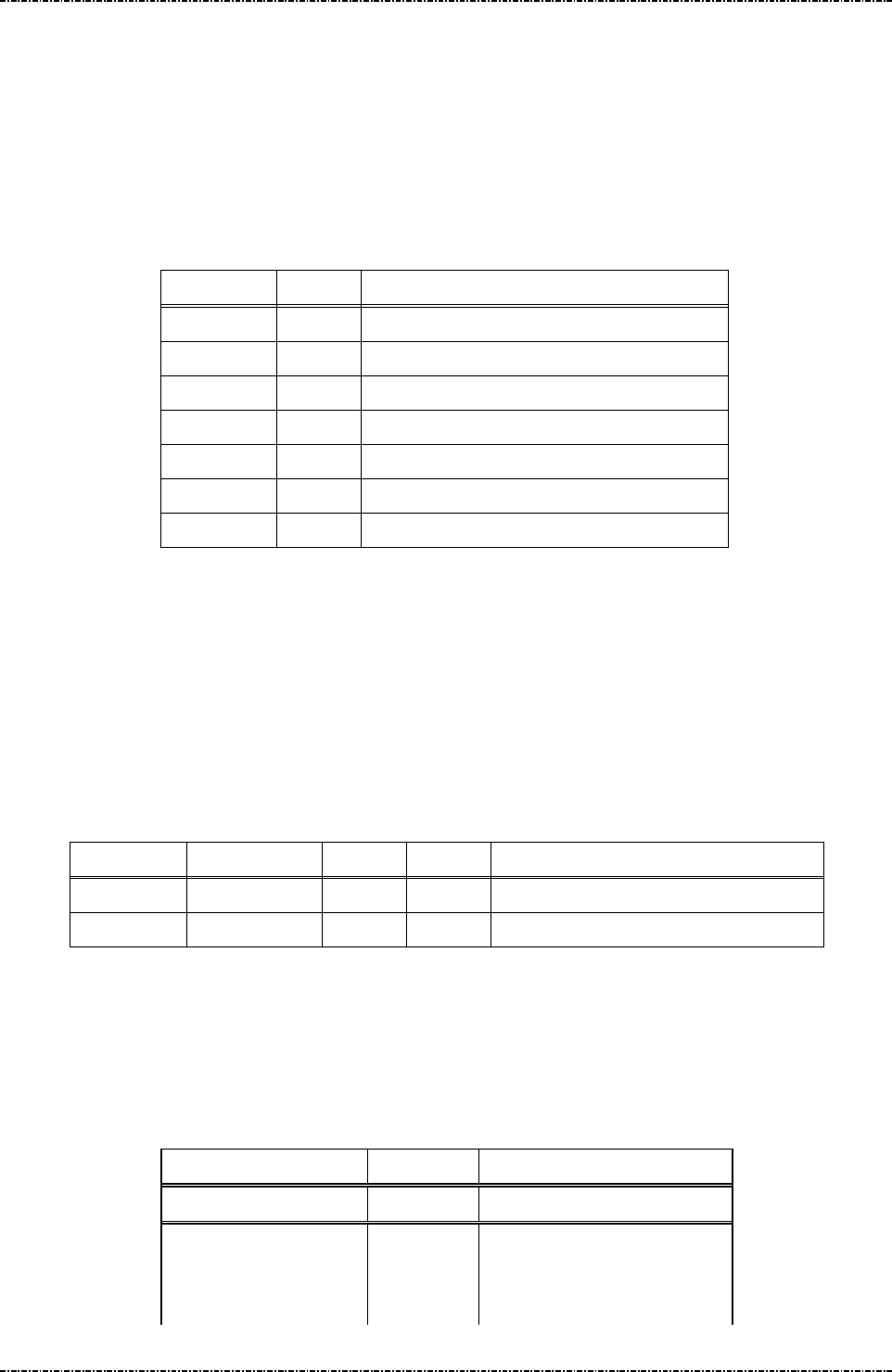
PIN Pad 791 Programmer’s Manual (PCI POS-A) UDN PM0103-U Rev. 06
Section 6 – Contact EMV Level 2 transaction messages 2015-04-20
Page81
Uniform Industrial Corp. Proprietary and Confidential Total 342 pages
Message T07 Data Format Table Setup
Format: <STX>T07[Clear]<SUB>[DO]<ETX>[LRC]
Message length: Variable.
Usage: PIN pad will check the consistent of TLV object from terminal via message T01 and
T05. Terminal can add more TLV format checking rules into PIN pad. PIN pad will send
the message T08 (Data Format Setup Response) to host.
Message element:
Field Length
Value and description
<STX> 1 <02>
T07 3 Message ID
Clear 1 ‘1’: Clear existed Data Format file
<SUB> 1 <1A, Optional, only if [DO] is existed
DO Var. Data Object, format as below
<ETX> 1 <03>
[LRC] 1 Checksum
Format of Data Objects:
The Data Objects for T07 shall include five data fields delimited by <FS>: [Tag#] <FS> [Format]
[Min Len] [Max Len] [Flag], Each data object is delimited by a <SUB> to construct multiple <DO>. If [flag]
is ‘0’, the data object will accept the length of value within [Min Len] and [Max Len]; if [flag] is ‘1’, the
data object will only accept ether [Min Len] or [Max Len] as valid length.
Example: (setup new data format.)
<STX>T070<SUB>5F88<FS>4021A0<SUB>5F99<FS>2080B1<ETX>[LRC]
In this example, PIN pad will check if the length of data with tag value 5F99 is 8-byte or 11-byte. PIN
pad will check if the length of data with tag value 5F88 is more than 1-byte and less than 27-byte.
Message flow:
HOST Direction PIN pad
1st Message T07
<ACK> (Good LRC)
<NAK> (Bad LRC)
<EOT> (after 3 NAKs)
Tag Data Format
Min Len
Max Len
Or Flag
5F88 4 02 1A 0 (data length is 2 ~ 26 bytes)
5F99 2 08 0B 1 (data length is 8 bytes or 11 bytes)

PIN Pad 791 Programmer’s Manual (PCI POS-A) UDN PM0103-U Rev. 06
Section 6 – Contact EMV Level 2 transaction messages 2015-04-20
Page82
Uniform Industrial Corp. Proprietary and Confidential Total 342 pages
1st Message T08
<ACK> (Good LRC)
<NAK> (Bad LRC)
<EOT> (after 3 NAKs)

PIN Pad 791 Programmer’s Manual (PCI POS-A) UDN PM0103-U Rev. 06
Section 6 – Contact EMV Level 2 transaction messages 2015-04-20
Page83
Uniform Industrial Corp. Proprietary and Confidential Total 342 pages
Message T08 Data Format Table Setup Response
Format: <STX>T08[Res][Reason][Err Msg]<ETX>[LRC]
Message length: Variable.
Usage: The response message of command T07.
Message element:
Field Length Value and description
<STX> 1 <02>
T08 3 Message ID
Res 1 ‘0’: Ok,
‘1’: Fail
Reason 1 ‘1’: Fatal Error
‘2’: Format Error
Err Message 8 Optional, if Reason = ‘1’Hex String
<ETX> 1 <03>
[LRC] 1 Checksum
Message flow: Please refer to message T07.
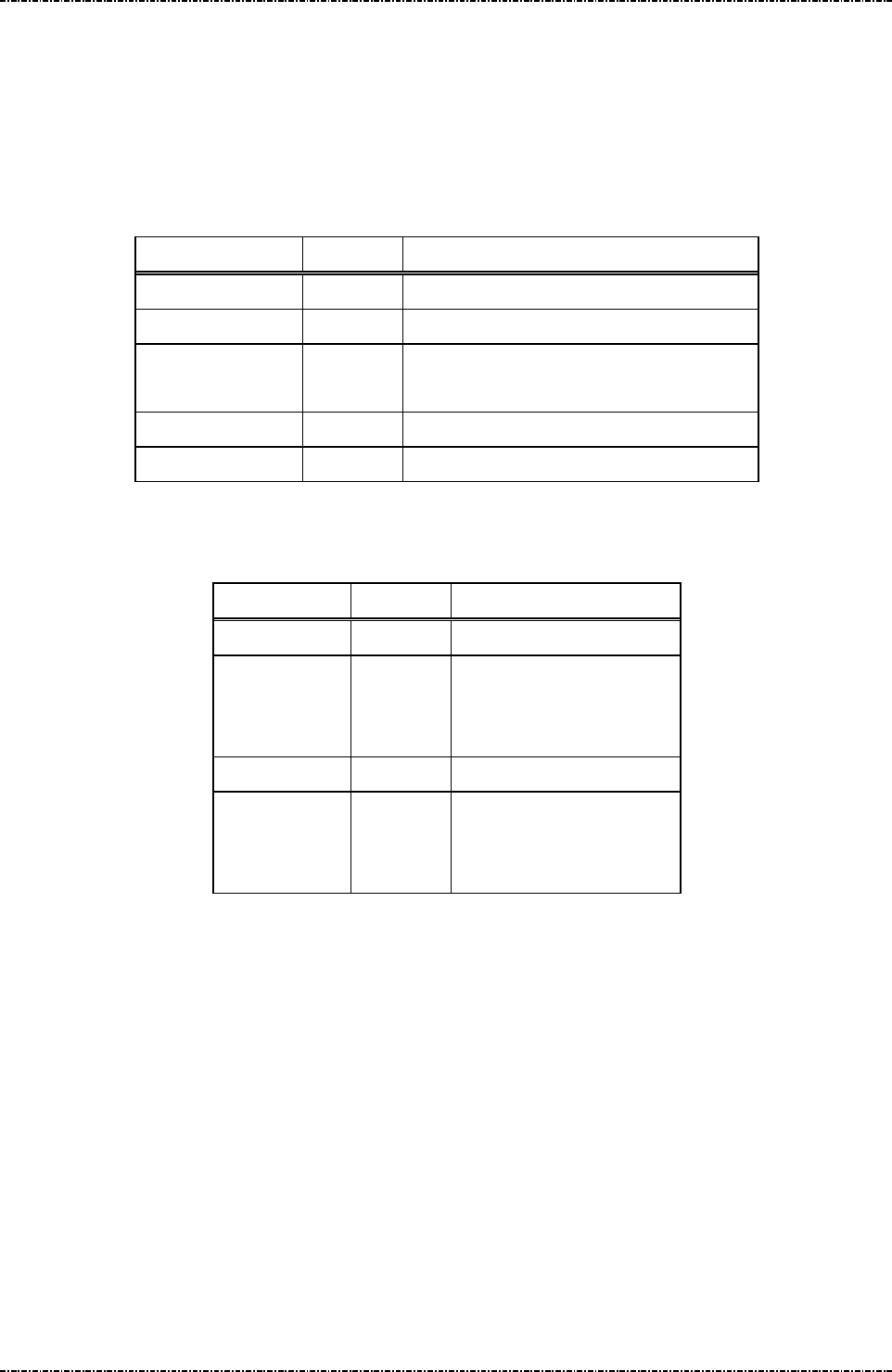
PIN Pad 791 Programmer’s Manual (PCI POS-A) UDN PM0103-U Rev. 06
Section 6 – Contact EMV Level 2 transaction messages 2015-04-20
Page84
Uniform Industrial Corp. Proprietary and Confidential Total 342 pages
Message T09 EMV Config Data Query Message
Format: <STX>T09[Config Type]<ETX>[LRC]
Message length: Fixed 7 bytes.
Usage: Get the group ID of EMV application data or CA public key stored in PIN pad.
Message element:
Field Length Value and description
<STX> 1 <02>
T09 3 Message ID
[Config Type] 1 1: All the IDs of CA public key.
2: All the IDs of EMV application data.
<ETX> 1 <03>
[LRC] 1 Checksum
Message flow:
HOST Direction PIN pad
Message T09
<ACK> (Good LRC)
<NAK> (Bad LRC)
<EOT> (after 3 NAKs)
Message T0A
<ACK>/
<NAK>/
<EOT>

PIN Pad 791 Programmer’s Manual (PCI POS-A) UDN PM0103-U Rev. 06
Section 6 – Contact EMV Level 2 transaction messages 2015-04-20
Page85
Uniform Industrial Corp. Proprietary and Confidential Total 342 pages
Message T0A Response of EMV Config Data Query Message
Format: <STX>T0A[Config Type][Status]<SUB>[ID List]<ETX>[LRC]
Message length: Variable.
Usage: Get the group ID of EMV application data or CA public key stored in PIN pad.
Message element:
Field Length Value and description
<STX> 1 <02>
T0A 3 Message ID
Config Type 1 Return the inputted data in the field [Config Type] of T09.
Status 1 0: There is data in identified data type.
1: No data in identified data type.
2: Arrange exceed.
<SUB> 1 <1A>, Optional if Status is 0
ID List Var Optional, if Status is 0.
[LRC] 1 Checksum
[ID List]: The concatenation of IDs. There is a <FS> between each ID.
Ex. [ID List] = A00000000390<FS> A000000004F8<FS> A000000004F5 ( Config Type = 1 )
[ID List] = A0000000041010<FS>B0123456781234<FS> A000000010 ( Config Type = 2 )
Message flow: Please refer to message T09.

PIN Pad 791 Programmer’s Manual (PCI POS-A) UDN PM0103-U Rev. 06
Section 6 – Contact EMV Level 2 transaction messages 2015-04-20
Page86
Uniform Industrial Corp. Proprietary and Confidential Total 342 pages
Message T0B Delete EMV Configuration Data Message.
Format: <STX>T0B[Config Type]<SUB>[ID List]<ETX>[LRC]
Message length: Variable.
Usage: Host can use this command to delete EMV application configuration data or CA
public key in PIN pad, this command can be sent many times.
Message element:
Field Length
Value and description
<STX> 1 <02>
T0B 3 Message ID
Config Type
1 1: CA public key.
2: EMV application data.
<SUB> 1 <1A>
ID List Var List of ID that will be erased.
<ETX> 1 <03>
[LRC] 1 Checksum
[ID List]: The concatenation of IDs. There is a <FS> between each ID.
Ex. [ID List] = A00000000390<FS> A000000004F8<FS> A000000004F5 ( Config Type = 1 )
[ID List] = A0000000041010<FS>B0123456781234<FS> A000000010 ( Config Type = 2 )
Message flow:
HOST Direction PIN pad
Message T0B
<ACK> (Good LRC)
<NAK> (Bad LRC)
<EOT> (after 3 NAKs)
Message T0C
<ACK> (Good LRC)
<NAK> (Bad LRC)
<EOT> (after 3 NAKs)

PIN Pad 791 Programmer’s Manual (PCI POS-A) UDN PM0103-U Rev. 06
Section 6 – Contact EMV Level 2 transaction messages 2015-04-20
Page87
Uniform Industrial Corp. Proprietary and Confidential Total 342 pages
Message T0C Response of Delete EMV Configuration Data Message.
Format: <STX>T0C[Config Type][Status]<SUB>[Del Result]<ETX>[LRC]
Message length: Variable.
Usage: The response message of command T0B.
Message element:
Field Length Value and description
<STX> 1 <02>
T0C 3 Message ID
Config Type 1 1: CA public key.
2: EMV application data.
Status 1 0: Delete OK
1: Fatal Error
2: Format error.
3: No CA public key or EMV application data
existed.
<SUB> 1 <1A>, Optional, if Status is 0.
Del Result var The results of delete operation on indicated ID
<ETX> 1 <03>
[LRC] 1 Checksum
[Del Result]: It’s the concatenation of results for delete operation on indicated ID. There is a <FS>
between each result. If the delete operation is successfully (When PIN pad finds
out the matched one and delete it successfully), the result is 0. If there is no such ID as
terminal specified, the result is 1.
Ex. Terminal issues message T0B to erase EMV application data with ID “A0000000102020”,
“A0000020” and “A0000000103030”. PIN pad now keeps EMV application data with ID
“A0000000103030” only.
The data in [Del Result] field will be “1<FS>1<FS>0”.
Message flow: Please refer to message T0B.

PIN Pad 791 Programmer’s Manual (PCI POS-A) UDN PM0103-U Rev. 06
Section 6 – Contact EMV Level 2 transaction messages 2015-04-20
Page88
Uniform Industrial Corp. Proprietary and Confidential Total 342 pages
Message T11 Application Select
Format: <STX>T11<ETX>[LRC]
Message length: Fixed 6 bytes.
Usage: PIN pad performs an application select on the active smart card. PIN pad will also
prompt user to insert its card if the card has not yet presented. PIN pad will send the
message T12 (Application Selection Response) to host.
Message element:
Field Length Value and description
<STX> 1 <02>
T11 3 Message ID
<ETX> 1 <03>
[LRC] 1 Checksum
Message flow:
HOST Direction PIN pad
Message T11
<ACK> (Good LRC)
<NAK> (Bad LRC)
<EOT> (after 3 NAKs)
Application Select Response.
Message T12
<ACK> (Good LRC)
<NAK> (Bad LRC)
<EOT> (after 3 NAKs)
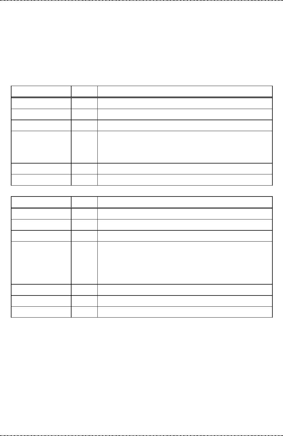
PIN Pad 791 Programmer’s Manual (PCI POS-A) UDN PM0103-U Rev. 06
Section 6 – Contact EMV Level 2 transaction messages 2015-04-20
Page89
Uniform Industrial Corp. Proprietary and Confidential Total 342 pages
Message T12 Application Select Response
Format: <STX>T12[Status][Reason][Application Name][ErrMessaeg]<ETX>[LRC]
Message length: Variable, depending on the length of returned application name.
Usage: The message contains the name of final selected application on the smart card to be
sent to host. In general, application name conforms to the EMV 4.3 level 2. See these
standards for more information.
Message element:
Field Length
Value and description
<STX> 1 <02>
T12 3 Message ID
Status 1 0:OK
[Application Name] 10-32 EMV application is selected successfully.
Format: Hexadecimal string. The content of this filed will not exist if
there is no EMV application can be selected.
<ETX> 1 <03>
[LRC] 1 Checksum
OR
Field Length
Value and description
<STX> 1 <02>
T12 3 Message ID
Status 1 1:Fail
Reason 1 1:Fatal Error
2:Command Format Error
3.Transaction Canceled
4.MSR processing.
[Err Message] 8 Optional, if Reason = ‘1’Hex String
<ETX> 1 <03>
[LRC] 1 Checksum
NOTE. According to EMV Level2’s rule, if IC card can not be read, PIN pad will return message “T1214”
to indicate that terminal should apply magnetic stripe card processing. In this situation, terminal
should issue message Q1 to get magnetic stripe data and issue message T1D to tell PIN pad the
data element in magnetic stripe card and message T15 to transmit necessary data (Amount,
transaction type, and so on.) to make PIN pad record enough information for this transaction.
Message flow: Please refer to message T11.

PIN Pad 791 Programmer’s Manual (PCI POS-A) UDN PM0103-U Rev. 06
Section 6 – Contact EMV Level 2 transaction messages 2015-04-20
Page90
Uniform Industrial Corp. Proprietary and Confidential Total 342 pages
Message T13 Application Select Next
Format: <STX>T13<ETX>[LRC]
Message length: Fixed 6 bytes.
Usage: If the selected EMV application is blocked (terminal will know that in message T16),
terminal could issue this message to ask PIN pad to display rest of EMV application for
cardholder selection.
Message element:
Field Length Value and description
<STX> 1 <02>
T13 3 Message ID
<ETX> 1 <03>
[LRC] 1 Checksum
Message flow:
HOST Direction PIN pad
Message T13
<ACK> (Good LRC)
<NAK> (Bad LRC)
<EOT> (after 3 NAKs)
Application Select Response.
Message T12
<ACK> (Good LRC)
<NAK> (Bad LRC)
<EOT> (after 3 NAKs)

PIN Pad 791 Programmer’s Manual (PCI POS-A) UDN PM0103-U Rev. 06
Section 6 – Contact EMV Level 2 transaction messages 2015-04-20
Page91
Uniform Industrial Corp. Proprietary and Confidential Total 342 pages
Message T15 Start Transaction
Format: <STX>T15<SUB>[AmtAuth]<SUB>[AmtOther]<SUB>
[CurExponent][CurCode]<SUB>[TranType]<SUB>[TranInfo]<SUB>
[Account Type]<SUB>[Force Online]<SUB>[Encrypted Session key]
<ETX>[LRC]
Message length: Variable.
Usage: PIN pad performs an completed EMV transaction flow (via ‘Initiate Application’ through
‘Completion’, see EMV 4.3, book 3, chap 8.2, figure 6 - transaction flow example)
based on the selected EMV application that has corrected application name on the
T12 (Application Select response), PIN pad will also prompt user to do the
appropriated entry when presented, like confirm or enter PIN code. PIN pad will send
the message T16 (Start Transaction Response) to host. If the IC card can not be read
(switch to magnetic stripe card processing), PIN pad will store the information provided
from this message and return the track data of magnetic stripe card and then finish
EMV transaction (The rest of operation on magnetic stripe card is outside scope of
EMV). Terminal could have extra operation on magnetic stripe card transaction (Issue
message 70 for PIN, and so on.).
Message element:
Field Length
Value and description
<STX> 1 <02>
T15 3 Message ID
<SUB> 1 <1A>
[AmtAuth] 12 Hexadecimal, Amount Authorized tag
‘0x9F02’
<SUB> 1 <1A>
[AmtOther] 12 Hexadecimal, Amount Other, tag
‘0x9F03’
<SUB> 1 <1A>
[CurExponent] 1 Hexadecimal, tag ‘0x5F36’
[CurCode] 3 Hexadecimal, tag ‘0x5F2A’.
For example, USD$ = 0x840
<SUB> 1 <1A>
[TranType] 2 Hexadecimal, Transaction Type, tag
‘0x9c’
<SUB> 1 <1A>
[TranInfo] 2 Transaction Info, tag ‘0x60000001’
<SUB> 1 <1A>
[Account Type]
2 Account Type, tag ‘0x5F57’

PIN Pad 791 Programmer’s Manual (PCI POS-A) UDN PM0103-U Rev. 06
Section 6 – Contact EMV Level 2 transaction messages 2015-04-20
Page92
Uniform Industrial Corp. Proprietary and Confidential Total 342 pages
<SUB> 1 <1A>
[Force Online]
1 1: Force Online
<SUB> 1 <1A>
[Encrypted
Session key]
16 or
32
(Optional, if the transaction needs user
to enter password for online authorized
and not session key exists, PIN pad
will ignore the password input and
indicate that no password is entered)
DES session key / TDES session key
used for EMV online PIN entry.
<ETX> 1 <03>
[LRC] 1 Checksum
Message flow:
HOST Direction PIN pad
Message T15
<ACK> (Good LRC)
<NAK> (Bad LRC)
<EOT> (after 3 NAKs)
Start Transaction Response.
Message T16
<ACK> (Good LRC)
<NAK> (Bad LRC)
<EOT> (after 3 NAKs)

PIN Pad 791 Programmer’s Manual (PCI POS-A) UDN PM0103-U Rev. 06
Section 6 – Contact EMV Level 2 transaction messages 2015-04-20
Page93
Uniform Industrial Corp. Proprietary and Confidential Total 342 pages
Message T16 Start Transaction Response
Format: <STX>T16[Status][Reason][Err Message][Result]<SUB>
<Advice Need><Reversal Need><Financial Need><ETX>[LRC]
Message length: Variable.
Usage: The message contains the transaction result on the smart card to be sent to terminal.
Message element:
Field Leng
th
Value and description
<STX> 1 <02>
T16 3 Message ID
Status 1 0:OK; 1:Fail
Reason 1 Optional. (If Status = 1)
1:Fatal Error
2:Command Format Error
Err Message 8 Optional, if Reason = ‘1’Hex String
Result 2 Optional. (If Status = 0)
‘Y1’: Offline Approved,
‘Z1’: Offline Declined
‘Y3’: Unable to go online,
Offline Approved
‘Z3’: Unable to go online, Offline Decline.
‘Y4’: Online Approved
‘Z4’: Online Decline
‘A1’: Online Authorize Request,
‘A4’: Application reselection.
<Reversal Need> 1 0: Terminal does not need to send a reversal to
host for this transaction
1: Terminal should send a reversal to host for this
transaction.
<ETX> 1 <03>
[LRC] 1 Checksum
Note: If the [Result] is ‘A1’, then terminal should send online authorization request to issuer host; and
after done, send message T17 to PIN pad to continue transaction. (See EMV 4.3, book 3, chap 9,
figure 7)
Note: If the transaction is switched to MSR processing, T16 will always return “A1” in [Result] field.
Note: If the previous selected application on IC card can’t do the transaction (for example, this

PIN Pad 791 Programmer’s Manual (PCI POS-A) UDN PM0103-U Rev. 06
Section 6 – Contact EMV Level 2 transaction messages 2015-04-20
Page94
Uniform Industrial Corp. Proprietary and Confidential Total 342 pages
application has blocked) but has another application ID within this IC card, PIN pad will response
‘A4’ to let terminal know and terminal can issue message T13 to select another application ID and
issue message T15 to re-start the transaction. Please refer the paragraph of “Ref. 5 Packet
command flow for first EMV application is blocked” in the section of “Overall EMV Level 2
transaction flow reference”.
Message flow: Please refer to message T15.

PIN Pad 791 Programmer’s Manual (PCI POS-A) UDN PM0103-U Rev. 06
Section 6 – Contact EMV Level 2 transaction messages 2015-04-20
Page95
Uniform Industrial Corp. Proprietary and Confidential Total 342 pages
Message T17 Send Online Authorized Code
Format: <STX>T17[OnlineRes]<SUB>[ARC]<SUB>[IAD]<ETX>[LRC]
Message length: Fixed 7 or 16 bytes.
Usage: PIN pad continues to perform the EMV transaction flow after received this online
response from host when the transaction response T16 is ‘A1’ (online authorized
request, see EMV 4.3, book 3, chap 8.2, figure 6 – transaction flow example). PIN pad
will send the message T16 (Start Transaction Response) to host.
Message element:
Field Length Value and description
<STX> 1 <02>
T17 3 Message ID
Online Res 1 ‘0’: Unable to go online
<ETX> 1 <03>
[LRC] 1 Checksum
OR
Field Length Value and description
<STX> 1 <02>
T17 3 Message ID
Online Res 1 ‘1’: Get Online Response,
<SUB> 1 <1A>
ARC 2 Optional, if there is ARC from host.
Authorisation Response code, ASCII
(0~9, A~Z),.
<SUB> 1 <1A>
[IAD] 16~32 Optional, if there is IAD from host.
Issuer Authentication Data , Hex string.
<ETX> 1 <03>
[LRC] 1 Checksum
OR (If the transaction is changed to Magnetic stripe card processing)
Field Length Value and description
<STX> 1 <02>
T17 3 Message ID
Online Res 1 ‘3’: MSR Online Approve
other: MSR Online Decline,
<ETX> 1 <03>
[LRC] 1 Checksum

PIN Pad 791 Programmer’s Manual (PCI POS-A) UDN PM0103-U Rev. 06
Section 6 – Contact EMV Level 2 transaction messages 2015-04-20
Page96
Uniform Industrial Corp. Proprietary and Confidential Total 342 pages
Note: If [Online Res] is ‘4’, then PIN pad will decide to approve or decline by the rule of TAC/IAC default.
Message flow:
HOST Direction PIN pad
Message T17
<ACK> (Good LRC)
<NAK> (Bad LRC)
<EOT> (after 3 NAKs)
Start Transaction Response.
Message T16
<ACK> (Good LRC)
<NAK> (Bad LRC)
<EOT> (after 3 NAKs)
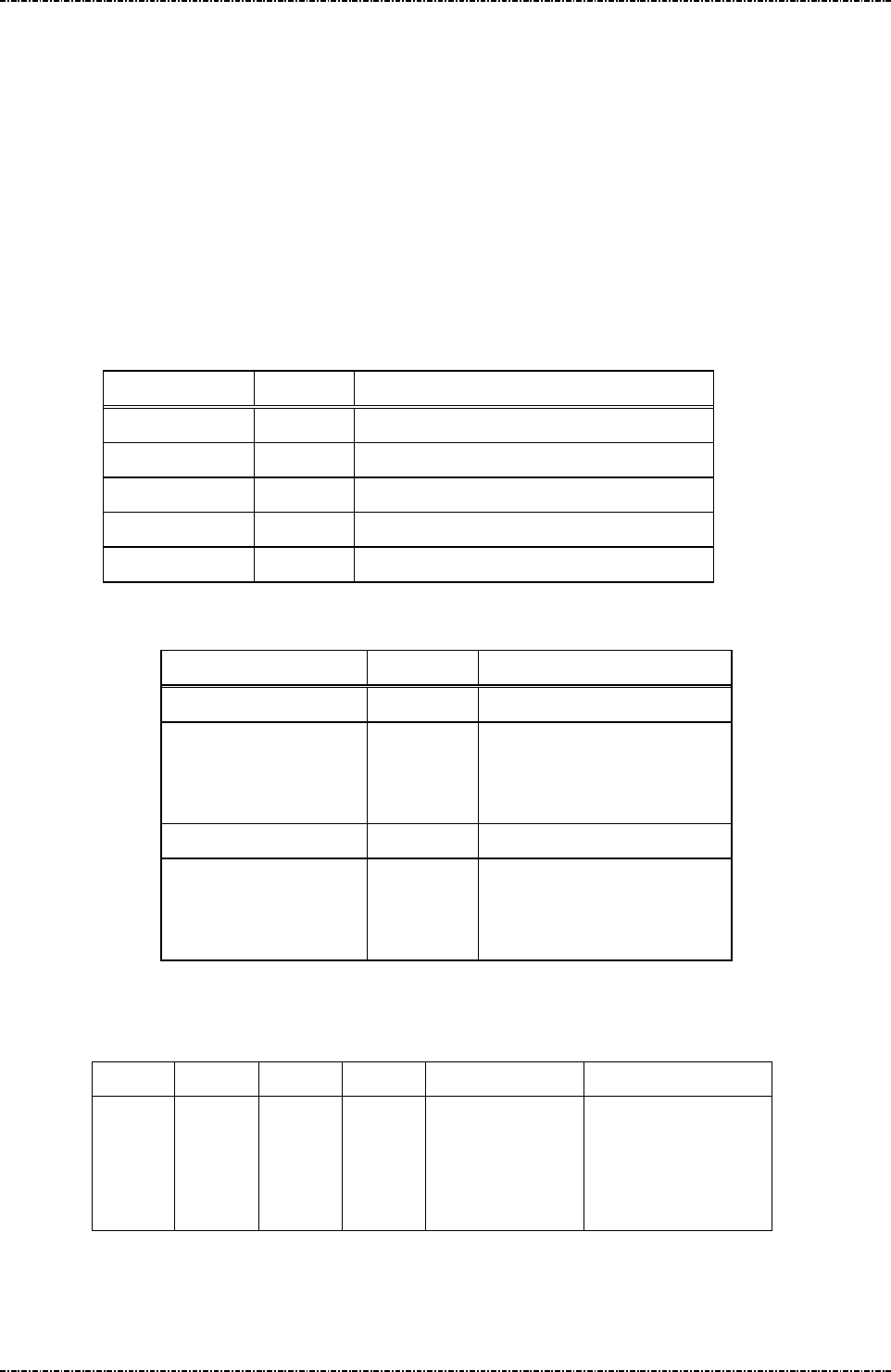
PIN Pad 791 Programmer’s Manual (PCI POS-A) UDN PM0103-U Rev. 06
Section 6 – Contact EMV Level 2 transaction messages 2015-04-20
Page97
Uniform Industrial Corp. Proprietary and Confidential Total 342 pages
Message T19 Send Issuer Script Command
Format: <STX>T19[IS]<ETX>[LRC]
Message length: Var.
Usage: PIN pad performs the Issuer script processing as in EMV transaction flow after
received this command from the host those are the response message when doing
online authorization. This command can be send many times if too many script
commands need to be processed, but the last one should be send before T17
command.
Message element:
Message flow:
HOST Direction PIN pad
Message T19
<ACK> (Good LRC)
<NAK> (Bad LRC)
<EOT> (after 3 NAKs)
Message T20
<ACK> (Good LRC)
<NAK> (Bad LRC)
<EOT> (after 3 NAKs)
Issuer Script Format: (see EMV 4.3, book 3, chap 10.10, Figure 14)
T L T L Script ID Commands
‘71’ or
‘72’
Including
Script ID,
tags,
lengths
‘9F18’ ‘04’ Identifier (4 bytes)
Issuer Script
Command Format
(see below)
Issuer Script Command Format: (see EMV 4.3, book 3, chap 10.10, Figure 15)
Field Length Value and description
<STX> 1 <02>
T19 3 Message ID
IS Var. Issuer Script, format as follow. Hex string.
<ETX> 1 <03>
[LRC] 1 Checksum

PIN Pad 791 Programmer’s Manual (PCI POS-A) UDN PM0103-U Rev. 06
Section 6 – Contact EMV Level 2 transaction messages 2015-04-20
Page98
Uniform Industrial Corp. Proprietary and Confidential Total 342 pages
T1 L1 V1 T2 L2 V2 T3 L3 V3 Tx Lx Vx
‘86’ L(V1)
Cmd
‘86’ L(V2)
Cmd
‘86’ L(V3)
Cmd
‘86’ L(Vx)
cmd

PIN Pad 791 Programmer’s Manual (PCI POS-A) UDN PM0103-U Rev. 06
Section 6 – Contact EMV Level 2 transaction messages 2015-04-20
Page99
Uniform Industrial Corp. Proprietary and Confidential Total 342 pages
Message T1D Transaction Data loading
Format: <STX>T1D<SUB>[DO]<ETX>[LRC]
Message length: Variable.
Usage: Terminal can use this command to send transaction data to PIN pad, this command
can be sent many times. PIN pad will save those data inside and apply those data
when do the transaction. PIN pad will send the message T1E to terminal.
Message element:
Field Length
Value and description
<STX> 1 <02>
T1D 3 Message ID
<SUB> 1 <1A, Optional, only if [DO] is existed
DO Var. Data Object, format as below
<ETX> 1 <03>
[LRC] 1 Checksum
Data Object:
Each <DO> shall include three data field: [Tag#] || [Format] || [Value], and each field shall
delimit with a <FS>. Each data object is delimited by a <SUB> to construct multiple <DO>. The
[tag#] defined in EMV 4.3 Book3 Annex A and specific [tag#] defined at Appendix D of this
manual have the pre-defined data format and length range, those [tag#] must follow up the rule,
otherwise the PP791 will reject this data setup. Any customer defined [tag#] number shall use
the command T07 pre-defined the data format and length range before load by this T1D
command.
Note. If the data format is ‘2’ (binary), ‘5’(compressed numeric), ‘6’(numeric) or ‘7’(variable data),
Data Format: (Please also refer to EMV 4.3 BOOK3, section 4.3)
Format
Description
1 a - Alphabetic data (a ~z, A~Z)
2 b - unsigned binary numbers or bit combinations
3 an - Alphanumeric data (a ~z, A~Z, 0~9)
4 ans - Alphanumeric Special data (Characters defined in ISO8859)
5 cn - Compressed numeric data (0~9, left justify, pad hexadecimal ‘F’s. Ex. 12 34 56 12 3F FF)
6 n - Numeric data (0~9, right justify, pad leading hexadecimal zeroes. Ex. 00 00 00 01 23 45)
7 var - Variable data (Any bit combination)
Example:
(IC card can not be read, terminal changes to MSR processing and then load these data into PIN pad.)
Service Code: 0211 (Numeric)

PIN Pad 791 Programmer’s Manual (PCI POS-A) UDN PM0103-U Rev. 06
Section 6 – Contact EMV Level 2 transaction messages 2015-04-20
Page100
Uniform Industrial Corp. Proprietary and Confidential Total 342 pages
PAN: 123456789022334455(Compressed Numeric)
Terminal sends,
<STX>T1D<SUB>5F30<FS>6<FS>0211<SUB>5A<FS>5<FS>123456789022334455<ETX>[LRC]
NOTE. The data from online host can be installed into PIN pad also. Please do not load ARC, IAD
and issuer scripts via this message.
NOTE. Terminal should issue this message to load online response data before issue message T17.
Message flow:
HOST Direction PIN pad
Message T1D
<ACK> (Good LRC)
<NAK> (Bad LRC)
<EOT> (after 3 NAKs)
Message T1E
<ACK> (Good LRC)
<NAK> (Bad LRC)
<EOT> (after 3 NAKs)

PIN Pad 791 Programmer’s Manual (PCI POS-A) UDN PM0103-U Rev. 06
Section 6 – Contact EMV Level 2 transaction messages 2015-04-20
Page101
Uniform Industrial Corp. Proprietary and Confidential Total 342 pages
Message T1E Transaction Data loading Response
Format: <STX>T1E[Res][Reason][Err Msg]<ETX>[LRC]
Message length: Variable.
Usage: The response message of command T1D.
Message element:
Field Length Value and description
<STX> 1 <02>
T1E 3 Message ID
Res 1 ‘0’: Ok,
‘1’: Fail
Reason 1 <Optional, if Res = ‘1’>
‘1’: Fatal Error
‘2’: Format Error
‘3’: Invalid Data Object format.
‘4’: Invalid Tag value
Err Message 8 Optional, if Reason = ‘1’, Hex decimal string
Err Tag Number Var. Optional, if Reason = ‘3’ or ‘4’, Hex decimal
string
<ETX> 1 <03>
[LRC] 1 Checksum
Message flow: Please refer to message T1D.

PIN Pad 791 Programmer’s Manual (PCI POS-A) UDN PM0103-U Rev. 06
Section 6 – Contact EMV Level 2 transaction messages 2015-04-20
Page102
Uniform Industrial Corp. Proprietary and Confidential Total 342 pages
Message T20 Send Issuer Script Command Response
Format: <STX>T20[Status][Reason][Err Message]<ETX>[LRC]
Message length: Variable.
Usage: The message response the command T19.
Message element:
Field Lengt
h
Value and description
<STX> 1 <02>
T20 3 Message ID
Status 1 0:OK ; 1:Fail
Reason 1 Optional. (if Status = 1)
1:Fatal Error
2:Command Format Error
Err Message 8 Optional, if Reason = ‘1’Hex String
<ETX> 1 <03>
[LRC] 1 Checksum
Message flow: Please refer to message T19.

PIN Pad 791 Programmer’s Manual (PCI POS-A) UDN PM0103-U Rev. 06
Section 6 – Contact EMV Level 2 transaction messages 2015-04-20
Page103
Uniform Industrial Corp. Proprietary and Confidential Total 342 pages
Message T21 Get Transaction Result’s Data
Format: <STX>T21[DOL]<ETX>[LRC]
Message length: Var.
Usage: PIN pad will retrieve the data that list on the DOL after EMV transaction done. PIN pad
will send the message T22 (Get Transaction Result’s Data Response) to host.
Message element:
Field Length Value and description
<STX> 1 <02>
T21 3 Message ID
DOL Var Data Object List, each object is expressed
by tag number, and <SUB> is used to
delimit each object. For example,
9F12<SUB>9A<SUB>9F02<SUB>….
<ETX> 1 <03>
[LRC] 1 Checksum
Message flow:
HOST Direction PIN pad
Message T21
<ACK> (Good LRC)
<NAK> (Bad LRC)
<EOT> after 3 NAKs
Get Transaction Result’s Data
Response.
Message T22
<ACK> (Good LRC)
<NAK> (Bad LRC)
<EOT> (after 3 NAKs)

PIN Pad 791 Programmer’s Manual (PCI POS-A) UDN PM0103-U Rev. 06
Section 6 – Contact EMV Level 2 transaction messages 2015-04-20
Page104
Uniform Industrial Corp. Proprietary and Confidential Total 342 pages
Message T22 Get Transaction Result’s Data Response
Format: <STX>T22[DO]<ETX>[LRC]
Message length: Var.
Usage: The message contains the transaction result’s data to be sent to host.
Message element:
Field Length Value and description
<STX> 1 <02>
T22 3 Message ID
[DO] Var Data Object, each data object is
expressed by TLV format with an
<FS> delimit in each field, and
<SUB> is used to delimit each
object. For example:
9F12<FS>0F<FS>CREDITO DE
VISA<SUB>9A<FS>06<FS>0508
06<SUB>…….
<ETX> 1 <03>
[LRC] 1 Checksum
Message flow: Please refer to message T21.

PIN Pad 791 Programmer’s Manual (PCI POS-A) UDN PM0103-U Rev. 06
Section 6 – Contact EMV Level 2 transaction messages 2015-04-20
Page105
Uniform Industrial Corp. Proprietary and Confidential Total 342 pages
Message T23 Erase EMV Transaction Log.
Format: <STX>T23<ETX>[LRC]
Message length: Fixed 6 bytes.
Usage: The message is used to purge the memory (flash) area for transaction logs.
Message element:
Field Length Value and description
<STX> 1 <02>
T23 3 Message ID
<ETX> 1 <03>
[LRC] 1 Checksum
Message flow:
HOST Direction PIN pad
Message T23
<ACK> (Good LRC)
<NAK> (Bad LRC)
<EOT> (after 3 NAKs)

PIN Pad 791 Programmer’s Manual (PCI POS-A) UDN PM0103-U Rev. 06
Section 6 – Contact EMV Level 2 transaction messages 2015-04-20
Page106
Uniform Industrial Corp. Proprietary and Confidential Total 342 pages
Message T1C Terminal Cancel Transaction
Format: <STX>T1C<ETX>[LRC]
Message length: Fixed 6 bytes
Usage: The message used to cancel the transaction..
Message element:
Field Length Value and description
<STX> 1 <02>
T1C 3 Message ID
<ETX> 1 <03>
[LRC] 1 Checksum
Message flow:
HOST Direction PIN pad
Message T1C
<ACK> (Good LRC)
<NAK> (Bad LRC)
<EOT> (after 3 NAKs)

PIN Pad 791 Programmer’s Manual (PCI POS-A) UDN PM0103-U Rev. 06
Section 6 – Contact EMV Level 2 transaction messages 2015-04-20
Page107
Uniform Industrial Corp. Proprietary and Confidential Total 342 pages
Message T25 Get Batch Data
Format: <STX>T25<ETX>[LRC]
Message length: Fixed 6 bytes.
Usage: Issue this message to get batch data (EMV).
Message element:
Field Length Value and description
<STX> 1 <02>
T25 3 Message ID
<ETX> 1 <03>
[LRC] 1 Checksum
Each issuing of message T25, PIN pad will return one of record in batched data via message T26.
Terminal could keep issuing message T25 until PIN pad return message to indicate that there is no more
record in batch data.
User can load a tag list of batch data into PIN pad, PIN pad will search the corresponding values
according to the tag list and store it as transaction record. Please refer to Appendix D for more details.
Note. If there is no more memory space for batch data, EMV transaction will be always failed transaction.
Please issue message T23 to release the memory space.
Note. PIN pad can store at most 1000 records.

PIN Pad 791 Programmer’s Manual (PCI POS-A) UDN PM0103-U Rev. 06
Section 6 – Contact EMV Level 2 transaction messages 2015-04-20
Page108
Uniform Industrial Corp. Proprietary and Confidential Total 342 pages
Message flow:
HOST Direction PIN pad
Message T25
<ACK> (Good LRC)
<NAK> (Bad LRC)
<EOT> (after 3 NAKs)
Message T26 (T262)
<ACK> (Good LRC)
<NAK> (Bad LRC)
<EOT> (after 3 NAKs)
Message T25
<ACK> (Good LRC)
<NAK> (Bad LRC)
<EOT> (after 3 NAKs)
Message T26 (T262)
<ACK> (Good LRC)
<NAK> (Bad LRC)
<EOT> (after 3 NAKs)
… … …
Message T25
<ACK> (Good LRC)
<NAK> (Bad LRC)
<EOT> (after 3 NAKs)
Message T26 (T261)
<ACK> (Good LRC)
<NAK> (Bad LRC)
<EOT> (after 3 NAKs)
PIN pad erases batch data.
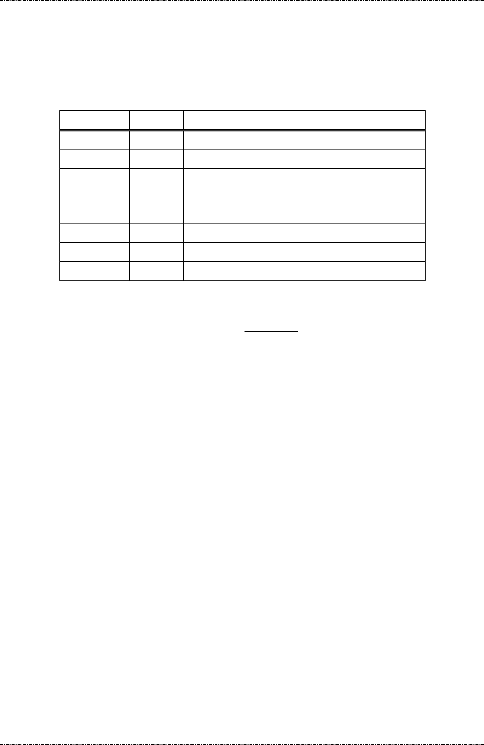
PIN Pad 791 Programmer’s Manual (PCI POS-A) UDN PM0103-U Rev. 06
Section 6 – Contact EMV Level 2 transaction messages 2015-04-20
Page109
Uniform Industrial Corp. Proprietary and Confidential Total 342 pages
Message T26 Response of Get Batch Data message
Format: <STX>T26[Status][record of Batch data]<ETX>[LRC]
Message length: var.
Usage: Return batch data to terminal.
Message element:
Field Length Value and description
<STX> 1 <02>
T26 3 Message ID
Status 1 0: No more record.
1: It is the last one record inside PIN pad.
2: There is still record inside PIN pad.
[Batch data] Var. Hex string.
<ETX> 1 <03>
[LRC] 1 Checksum
Format of Batch data:
According to the tag list of batch data (refer to Appendix D), PIN pad will search the corresponding
values according to the tag list and store it as transaction record.
[EMV Tag Number (1 ~ 4 byte)] || [Length (1byte)] || [Value] || [EMV Tag Number (1 ~ 4 byte)] || [Length
(1byte)] || [Value] || …[EMV Tag Number (1 ~ 4 byte)] || [Length (1byte)] || [Value]. PIN pad can save at
most 256 bytes of data as one record, the right part of data will be ignored if the length record is greater
than 256 byte.
PIN pad will unpack the binary data into hex string and return to terminal. For example, the data of one
record is 0x9F02 || 06 || 000000001100 || 5A || 10 || 1122334455667 7889900AABBCCDDEEFF,
terminal will see “9F02060000000011005A1011223344556677889900A
ABBCCDDEEFF” in [Batch data] field.
Message flow: Please refer to message T25
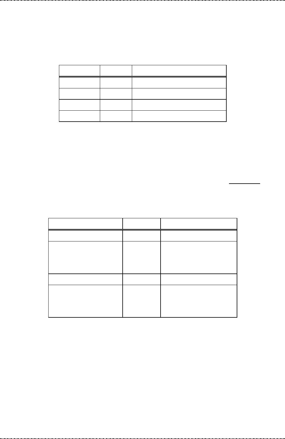
PIN Pad 791 Programmer’s Manual (PCI POS-A) UDN PM0103-U Rev. 06
Section 6 – Contact EMV Level 2 transaction messages 2015-04-20
Page110
Uniform Industrial Corp. Proprietary and Confidential Total 342 pages
Message T27 Get Online authorization Data
Format: <STX>T27<ETX>[LRC]
Message length: Fixed 6 bytes.
Usage: Issue this message to get data (EMV) for online authorization.
Message element:
Field Length Value and description
<STX> 1 <02>
T27 3 Message ID
<ETX> 1 <03>
[LRC] 1 Checksum
While the EMV transaction must be authorized online, issuing message T27 to get the necessary data for
online authorization from PIN pad. If the transaction must be authorized online, PIN pad
User can load a tag list for online authorization data into PIN pad, PIN pad will search the corresponding
values according to the tag list and return it as transaction record. Please refer to Appendix D for more
details.
Message flow:
HOST Direction PIN pad
Message T27
<ACK> (Good LRC)
<NAK> (Bad LRC)
<EOT> (after 3 NAKs)
Message T28
<ACK> (Good LRC)
<NAK> (Bad LRC)
<EOT> (after 3 NAKs)

PIN Pad 791 Programmer’s Manual (PCI POS-A) UDN PM0103-U Rev. 06
Section 6 – Contact EMV Level 2 transaction messages 2015-04-20
Page111
Uniform Industrial Corp. Proprietary and Confidential Total 342 pages
Message T28 Response of Get Online authorization Data message
Format: <STX>T28[record of online authorization data]<ETX>[LRC]
Message length: var.
Usage: Return online authorization data to terminal.
Message element:
Field Length Value and description
<STX> 1 <02>
T28 3 Message ID
Online authorization data Var. Hex string.
Optional, if this transaction needs to be
authorized online.
<ETX> 1 <03>
[LRC] 1 Checksum
Online authorization data:
According to the tag list of online authorization data (refer to Appendix D), PIN pad will search the
corresponding values according to the tag list and return it as transaction record.
[EMV Tag Number (1 ~ 4 byte)] || [Length (1byte)] || [Value] || [EMV Tag Number (1 ~ 4 byte)] || [Length
(1byte)] || [Value] || …[EMV Tag Number (1 ~ 4 byte)] || [Length (1byte)] || [Value]. PIN pad can return at
most 256 bytes of data as one record, the right part of data will be ignored if the length record is greater
than 256 byte.
PIN pad will unpack the binary data into hex string and return to terminal. For example, the data of one
record is 0x9F02 || 06 || 000000001100 || 5A || 10 || 11223344556677889900AABBC
CDDEEFF, terminal will see “9F02060000000011005A1011223344556677889900AABBCCDDEEFF”
in [Batch data] field.
Message flow: Please refer to message T27
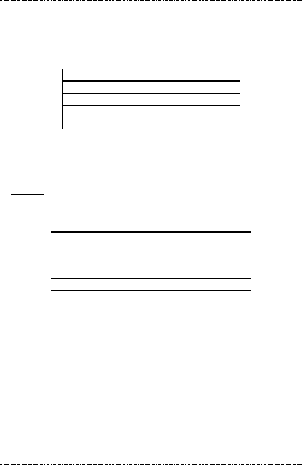
PIN Pad 791 Programmer’s Manual (PCI POS-A) UDN PM0103-U Rev. 06
Section 6 – Contact EMV Level 2 transaction messages 2015-04-20
Page112
Uniform Industrial Corp. Proprietary and Confidential Total 342 pages
Message T29 Get Reversal Data
Format: <STX>T29<ETX>[LRC]
Message length: Fixed 6 bytes.
Usage: Issue this message to get data (EMV) for reversal.
Message element:
Field Length Value and description
<STX> 1 <02>
T29 3 Message ID
<ETX> 1 <03>
[LRC] 1 Checksum
While the EMV transaction needs a reversal, issuing message T29 to get the necessary data for reversal
from PIN pad. User can load a tag list for reversal data into PIN pad, PIN pad will search the
corresponding values according to the tag list and return it as transaction record. Please refer to
Appendix D for more details.
Message flow:
HOST Direction PIN pad
Message T29
<ACK> (Good LRC)
<NAK> (Bad LRC)
<EOT> (after 3 NAKs)
Message T2A
<ACK> (Good LRC)
<NAK> (Bad LRC)
<EOT> (after 3 NAKs)
Note. Terminal could always get reversal data even if the message T16 indicates that the reversal is not
needed.

PIN Pad 791 Programmer’s Manual (PCI POS-A) UDN PM0103-U Rev. 06
Section 6 – Contact EMV Level 2 transaction messages 2015-04-20
Page113
Uniform Industrial Corp. Proprietary and Confidential Total 342 pages
Message T2A Response of Get Reversal Data message
Format: <STX>T2A[record of Reversal data]<ETX>[LRC]
Message length: var.
Usage: Return reversal data to terminal..
Message element:
Field Length Value and description
<STX> 1 <02>
T2A 3 Message ID
Reversal data Var. Hex string.
Optional, if this transaction needs a reversal.
<ETX> 1 <03>
[LRC] 1 Checksum
Reversal data:
According to the tag list of reversal data (refer to Appendix D), PIN pad will search the corresponding
values according to the tag list and return it as transaction record.
[EMV Tag Number (1 ~ 4 byte)] || [Length (1byte)] || [Value] || [EMV Tag Number (1 ~ 4 byte)] || [Length
(1byte)] || [Value] || …[EMV Tag Number (1 ~ 4 byte)] || [Length (1byte)] || [Value]. PIN pad can return at
most 256 bytes of data as one record, the right part of data will be ignored if the length record is greater
than 256 byte.
PIN pad will unpack the binary data into hex string and return to terminal. For example, the data of one
record is 0x9F02 || 06 || 000000001100 || 5A || 10 || 11223344556677889900AABBC
CDDEEFF, terminal will see “9F02060000000011005A1011223344556677889900AABBCCDDEEFF”
in [Batch data] field.
Message flow: Please refer to message T29

PIN Pad 791 Programmer’s Manual (PCI POS-A) UDN PM0103-U Rev. 06
Section 6 – Contact EMV Level 2 transaction messages 2015-04-20
Page114
Uniform Industrial Corp. Proprietary and Confidential Total 342 pages
Overall Contact EMV Level 2 transaction flow reference
Ref. 1 Packet command flow for transaction with offline
HOST Direction PIN pad
T11 (Application Select )
T12 (Application Select Response)
T15 (Start Transaction)
T16 (Start Transaction Response)
[Result] = ‘Y1’ or ‘Z1’
T21 (Get Transaction Result’s Data)
T22 (Get Transaction Result’s Data
Response)
Ref. 2 Packet command flow for transaction with online
HOST Direction PIN pad
T11 (Application Select )
T12 (Application Select Response)
T15 (Start Transaction)
T16 (Start Transaction Response)
[Result] = ‘A1’
T27 (Get online data from PIN pad)
T28 (Online authorization data response)
Go Online
T1D (Send necessary online response
data to PIN pad.)
T1E
T17 (Send Online Authorized Code)
T16 (Start Transaction Response)
[Result] = ‘Y3’ or ‘Y4’ or ‘Z3’ or ‘Z4’
T21 (Get Transaction Result’s Data)
T22 (Get Transaction Result’s Data
Response)

PIN Pad 791 Programmer’s Manual (PCI POS-A) UDN PM0103-U Rev. 06
Section 6 – Contact EMV Level 2 transaction messages 2015-04-20
Page115
Uniform Industrial Corp. Proprietary and Confidential Total 342 pages
Ref. 3 Packet command flow for transaction with MSR.
HOST Direction PIN pad
T11 (Application Select )
T12 (Application Select Response
indicates that PIN pad fails to read IC
card)
Issue magnetic stripe card commands
T1D (Send necessary magnetic stripe
card data to PIN pad.)
T1E
T15 (Start Transaction)
T16 (Start Transaction Response)
[Result] = ‘A1’
Go Online
T1D (Send necessary online response
data to PIN pad.)
T1E
T17 (Send Online Authorized Code)
T16 (Start Transaction Response)
[Result] = ‘Y4’ or ‘Z4’
T21 (Get Transaction Result’s Data)
T22 (Get Transaction Result’s Data
Response)

PIN Pad 791 Programmer’s Manual (PCI POS-A) UDN PM0103-U Rev. 06
Section 6 – Contact EMV Level 2 transaction messages 2015-04-20
Page116
Uniform Industrial Corp. Proprietary and Confidential Total 342 pages
Ref. 4 Packet command flow for transaction with online and Issuer Script command
Processing
HOST Direction PIN pad
T11 (Application Select )
T12 (Application Select Response)
T15 (Start Transaction)
T16 (Start Transaction Response)
[Result] = ‘A1’
T27 (Get online data from PIN pad)
T28 (Online authorization data response)
Go Online
T19 (Send Issuer Script command)
(if many commands)
T20 (Send Issuer Script command
Response, continued)
T1D (Send necessary online response
data to PIN pad.)
T1E
T17 (Send Online Authorized Code)
T16 (Start Transaction Response)
[Result] = ‘Y3’ or ‘Y4’ or ‘Z3’ or ‘Z4’
T21 (Get Transaction Result’s Data)
T22 (Get Transaction Result’s Data
Response)
Ref. 5 Packet command flow for first EMV application is blocked
HOST Direction PIN Pad
T11 (Application Select )
T12 (Application Select Response)
T15 (Start Transaction)
T16 (Start Transaction Response)
[Result] = ‘A4’
T13 (Application Select Next)
T12 (Application Select Response)

PIN Pad 791 Programmer’s Manual (PCI POS-A) UDN PM0103-U Rev. 06
Section 6 – Contact EMV Level 2 transaction messages 2015-04-20
Page117
Uniform Industrial Corp. Proprietary and Confidential Total 342 pages
T15 (Start Transaction)
T16 (Start Transaction Response)
[Result] = ‘Y1’ or ‘Z1”
T21 (Get Transaction Result’s Data)
T22 (Get Transaction Result’s Data
Response)

PIN Pad 791 Programmer’s Manual (PCI POS-A) UDN PM0103-U Rev. 06
Section 7 – Contactless EMV Level 2 transaction messages 2015-04-20
Page118
Uniform Industrial Corp. Proprietary and Confidential Total 342 pages
Section 7 Contactless EMV Level 2 transaction messages
Contactless EMV Level2 transaction messages are divided into 2 groups. One is EMV-configuration data
operation messages (T51, T53, T55 ,T75, T77 ) and the other one is EMV-transaction messages (T61, T63,
T65, T6C, T71 and T73).
The PCD EMV transaction messages issuing sequence is control by PIN pad, an invalid sequence will
terminate PCD EMV transaction. Message T61 is used for terminal-side to transmit transaction information
such as amount and then PIN pad do a complete transaction with card if the transaction needs not to be
authorized online. Message T71 is applied if the transaction needs to be authorized online, terminal-side will
transmit necessary information via this message to PIN pad to continue the rest steps of transaction. If the
response from host contains issuer script (see EMV Book), terminal-side applies message T73 to input these
scripts into PIN pad and PIN pad will issue these scripts at appropriate time to card. Message T6C is used to
terminate an EMV transaction. Finally, message T65 is used for terminal-side to get the transaction
information through PCD EMV transaction. The transaction flow chart could be referred in “Overall
Contactless EMV level 2 transaction flow reference” section.

PIN Pad 791 Programmer’s Manual (PCI POS-A) UDN PM0103-U Rev. 06
Section 7 – Contactless EMV Level 2 transaction messages 2015-04-20
Page119
Uniform Industrial Corp. Proprietary and Confidential Total 342 pages
The meaning of error code in the [Err Message] are listed below:
Error Code Error Description
00000003 Service not accepted.
00000F9B Store configuration data error.
8FFF0001 Out of memory.
8FFF0002 Parameter error.
8FFFFF02 Tag’s data format error.
8FFFFF03 Some mandatory tags are not configured well.
8FFFFFF0 Command format error.
8FFFFFF1 The sequence of EMV transaction command is error.
8FFFFFF2 Terminal fundamental data is missing.
8FFFFFF3 Authentication failed.
8FFFFF1A Authentication key expired.
8FFFFF1B Terminal configuration data is missing.
8FFFFF1C No configuration data of EMV application or the data is missing.
8FFFFFF4 The storage space of batch data capture is full.
8FFFFFF5 No terminal configuration data, EMV application configuration data or CA public key.
A2000001 Application initial conditions are not satisfied.
A2000002 The generated cryptogram is not allowed.
A2000007 The instruction ID of the specified is not recognized.
A200000A The type to request application cryptogram is incorrect.
A200000C The status response (SW1 SW2) is other than ‘9000’.
A200000D The Generate AC command is called more than 2 times in the current transaction.
A200000E The AIP mandatory data is missing in response data from card.
A200000F The AFL mandatory data is missing in response data from card.
A2000010 The response template from card isn't correct.
A2000011 The format of AFL is incorrect.
A2000013 A redundant data output from card is not allowed.
A2000014 Missing mandatory data in response data from card.
EFFFFFFF EMV transaction cancelled.
DFFFFFFF EMV forced abort.
FFFF0001 There is an error when parse the TLV list data.
FFFFFFFF The contactless card doesn’t response data.
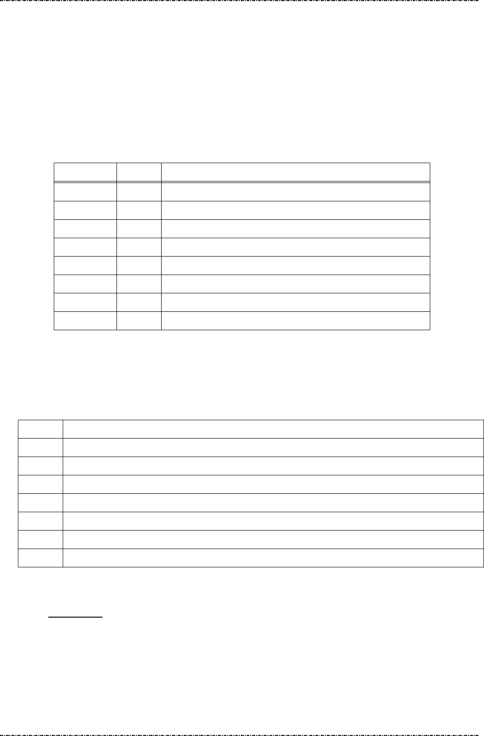
PIN Pad 791 Programmer’s Manual (PCI POS-A) UDN PM0103-U Rev. 06
Section 7 – Contactless EMV Level 2 transaction messages 2015-04-20
Page120
Uniform Industrial Corp. Proprietary and Confidential Total 342 pages
Message T51 PCD Terminal Configuration Setup
Format: <STX>T51[Pkt No.][Total Pkts]<SUB>[DO]<ETX>[LRC]
Message length: Variable.
Usage: Host can use this command to send terminal configuration data to PIN pad, this
command can be sent many times. PIN pad will save those data inside and apply
those data when do the transaction. PIN pad will send the message T52 (Terminal
Configuration Setup Response) to host.
Message element:
Field Length
Value and description
<STX> 1 <02>
T51 3 Message ID
Pkt No. 1 Decimal. Packet sequence number (1 ~ 9)(ex. 2)
Total Pkts 1 Decimal. Total packets (1~9)(ex. 8).
<SUB> 1 <1A, Optional, only if [DO] is existed
DO Var. Data Object, format as below
<ETX> 1 <03>
[LRC] 1 Checksum
Data Object Format: each data object is delimited by <SUB>, and each field inside each data
object is delimited by <FS>.
Data Format: (Please also refer to EMV Contactless Specifications v2.4,)
Format
Description
1 a - Alphabetic data (a ~z, A~Z)
2 b - unsigned binary numbers or bit combinations
3 an - Alphanumeric data (a ~z, A~Z, 0~9)
4 ans - Alphanumeric Special data (Characters defined in ISO8859)
5 cn - Compressed numeric data (0~9, left justify, pad hexadecimal ‘F’s. Ex. 12 34 56 12 3F FF)
6 n - Numeric data (0~9, right justify, pad leading hexadecimal zeroes. Ex. 00 00 00 01 23 45)
7 var - Variable data (Any bit combination)
Note. User has to obey the restriction specified in EMV Contactless Specifications v2.4, and
Appendix F of this document to load configuration data. PIN pad will check if the length of
each configuration data item is consistent. Any inconsistent data item will make data
loading fail.
Note. If the data format is ‘2’ (binary), ‘5’(compressed numeric), ‘6’(numeric) or ‘7’(variable data),
it can not be allocated in message T51 directly. It should be transferred into hexadecimal
string and then allocated in message T51.

PIN Pad 791 Programmer’s Manual (PCI POS-A) UDN PM0103-U Rev. 06
Section 7 – Contactless EMV Level 2 transaction messages 2015-04-20
Page121
Uniform Industrial Corp. Proprietary and Confidential Total 342 pages
Example: (Clear the terminal configuration data and then setup new data.)
Merchant Category Code: 0000 (Numerical)
Terminal ID: SmartPOS (Ascii)
UI Capability: 0x01 (binary)
<STX>T5111<SUB>9f15<FS>6<FS>0000<SUB>9f1c<FS>3<FS>SmartPOS<SUB>
50000002<FS>2<FS>01<ETX>[LRC]
Special Tag for PIN pad: 0x50000001, 0x50000002
Name Description Format Tag Length
Terminal UI
Capability
0: Make PIN pad selects the highest
priority application without cardholder’s
confirmation.
B 50000002 1
These data object are defined in EMV Contactless Specifications v2.4,, without tag values. The tag
values are
defined by UIC.
PIN pad will check if terminal downloads minimum set of terminal-related information into PIN
pad. The download process will be failed if there is not enough data in this message. Please
refer to Appendix G for minimum set of terminal-related data
Message flow:
HOST Direction PIN pad
1st Message T51
<ACK> (Good LRC)
<NAK> (Bad LRC)
<EOT> (after 3 NAKs)
1st Message T52
<ACK> (Good LRC)
<NAK> (Bad LRC)
<EOT> (after 3 NAKs)
2nd Message T51
<ACK> (Good LRC)
<NAK> (Bad LRC)
<EOT> (after 3 NAKs)
2nd Message T52
<ACK> (Good LRC)
<NAK> (Bad LRC)
<EOT> (after 3 NAKs)

PIN Pad 791 Programmer’s Manual (PCI POS-A) UDN PM0103-U Rev. 06
Section 7 – Contactless EMV Level 2 transaction messages 2015-04-20
Page122
Uniform Industrial Corp. Proprietary and Confidential Total 342 pages
… … …
Last one Message T51
<ACK> (Good LRC)
<NAK> (Bad LRC)
<EOT> (after 3 NAKs)
Last one Message T52
<ACK> (Good LRC)
<NAK> (Bad LRC)
<EOT> (after 3 NAKs)

PIN Pad 791 Programmer’s Manual (PCI POS-A) UDN PM0103-U Rev. 06
Section 7 – Contactless EMV Level 2 transaction messages 2015-04-20
Page123
Uniform Industrial Corp. Proprietary and Confidential Total 342 pages
Message T52 PCD Terminal Configuration Setup Response
Format: <STX>T52[Res][Reason][Err Msg][Err Tag Number]<ETX>[LRC]
Message length: Variable.
Usage: The response message of command T51.
Message element:
Field Length Value and description
<STX> 1 <02>
T52 3 Message ID
Res 1 ‘0’: Ok,
‘1’: Fail
Reason 1 <Optional, if Res = ‘1’>
‘1’: Fatal Error
‘2’: Format Error
‘3’: Invalid Data Object format.
‘4’: Invalid Tag value
Err Message 8 Optional, if Reason = ‘1’, Hex decimal string
Err Tag Number Var. Optional, if Reason = ‘3’ or ‘4’, Hex decimal
string
<ETX> 1 <03>
[LRC] 1 Checksum
Message flow: Please refer to message T51.

PIN Pad 791 Programmer’s Manual (PCI POS-A) UDN PM0103-U Rev. 06
Section 7 – Contactless EMV Level 2 transaction messages 2015-04-20
Page124
Uniform Industrial Corp. Proprietary and Confidential Total 342 pages
Message T53 PCD Certification Authority Public Key Setup
Format: <STX>T53[Op code][RID][PKI][Hash Algo][Hash][PK Algo][PK Leng]
[PK Exponent]<ETX>[LRC]
<STX>T53[Op code][PK Modulus]<ETX>
Message length: Variable.
Usage: Host can use this command to send the Certification Authority Public key data to
PIN pad, each command can only setup one key but this command can be sent many
times. PIN pad will save those key data inside and use those data when do the
transaction. PIN pad will send the message T54 (Certification Authority Public Key
Setup Response) to host. The data installed into PIN pad via this message, PIN pad
will save it in internal storage structure with a name same as concatenation of value in
[RID] and [PKI] fields. Ex. value in [RID] field is “A000000003”, value in [PKI] filed is
“90”, PIN pad will save these data and give an ID as “A00000000390”.
Message element:
1st Packet (Load RSA public key):
Field Length
Value and description
<STX> 1 <02>
T53 3 Message ID
Op code 1 1: Load first part of RSA public key
RID 10 Hexadecimal string, the left 5 bytes of Registered
Application Provider ID
PKI 2 Public Key Index, hexadecimal string. (Refer to
EMV Contactless Specifications v2.4, tag ‘9F22’)
Hash
Algorithm
2 Hash Algorithm Index, hexadecimal string
‘01’: SHA-1. Now, PIN pad accepts only ‘01’.
Hash 40 Hash checksum, hexadecimal.
Sha1(PKModules)
or
Sha1(RID+PKI+PKModules+PKExp)
PK
Algorithm
2 Public Key Algorithm, hexadecimal string
‘01’: RSA digital signature. Now, PIN pad accepts
only ‘01’.
PK Leng 2 Public Key size, hexadecimalstring, for example:
‘80’ = 128 bytes = 1024 bits
PK
Exponent
1 Public Key Exponent’s size, hexadecimal
1: 3
2: 216+1

PIN Pad 791 Programmer’s Manual (PCI POS-A) UDN PM0103-U Rev. 06
Section 7 – Contactless EMV Level 2 transaction messages 2015-04-20
Page125
Uniform Industrial Corp. Proprietary and Confidential Total 342 pages
<ETX> 1 <03>
[LRC] 1 Checksum
2nd Packet (Load RSA public key):
Field Length Value and description
<STX> 1 <02>
T53 3 Message ID
Op code 1 2: Load second part of RSA public key
PK
Modulus
Var Public Key Modulus, presented in
hexadecimal, data length = 2*[PK length]
<ETX> 1 <03>
[LRC] 1 Checksum
Message flow:
HOST Direction PIN pad
1st Message T53
<ACK> (Good LRC)
<NAK> (Bad LRC)
<EOT> (after 3 NAKs)
1st CA Public Key Setup
Response Message T54
<ACK> (Good LRC)
<NAK> (Bad LRC)
<EOT> (after 3 NAKs)
2nd Message T53
<ACK> (Good LRC)
<NAK> (Bad LRC)
<EOT> (after 3 NAKs)
2nd CA Public Key Setup
Response Message T54
<ACK> (Good LRC)
<NAK> (Bad LRC)
<EOT> (after 3 NAKs)

PIN Pad 791 Programmer’s Manual (PCI POS-A) UDN PM0103-U Rev. 06
Section 7 – Contactless EMV Level 2 transaction messages 2015-04-20
Page126
Uniform Industrial Corp. Proprietary and Confidential Total 342 pages
Message T54 PCD Certification Authority Public Key Setup Response
Format: <STX>T54[Sequence][Res][Reason][Err Msg]<ETX>[LRC]
Message length: Variable.
Usage: The response message of command T53.
Message element:
1st, 2nd Packet:
Field Length Value and description
<STX> 1 <02>
T54 3 Message ID
Sequence 1 1 / 2 (first/second part of RSA public key)
Res 1 ‘0’: Ok,
‘1’: Fail
Reason 1 ‘1’: Fatal Error
‘2’: Format Error
‘3’: Authentication Fail
Err Message 8 Optional, if Reason = ‘1’Hex String
<ETX> 1 <03>
[LRC] 1 Checksum
Message flow: Please refer to message T53.

PIN Pad 791 Programmer’s Manual (PCI POS-A) UDN PM0103-U Rev. 06
Section 7 – Contactless EMV Level 2 transaction messages 2015-04-20
Page127
Uniform Industrial Corp. Proprietary and Confidential Total 342 pages
Message T55 PCD Application Configuration Setup
Format: <STX>T55[Pkt No.][Total Pkts]<SUB>[TXN]<SUB>[KID]<SUB>[AID]<SUB>
[DO]<ETX>[LRC]
<STX>T55[Pkt No.][Total Pkts]<SUB>[DO]<ETX>[LRC]
Message length: Variable.
Usage: Host can use this command to send the EMV application configuration data to PIN
pad, this command can be sent many times but each command is only for one
application. PIN pad will save those data inside and use those data when do the
transaction. PIN pad will send the message T56 (EMV Application Configuration Setup
Response) to host. The data installed into PIN pad via this message, PIN pad will save
it in internal storage structure with a name same as in [AID] field.
Message element:
1st Message:
Field Length
Value and description
<STX> 1 <02>
T55 3 Message ID
Pkt No. 1 Decimal. Packet sequence number (1 ~ 9)
Total Pkts 1 Decimal. Total packets (1~9)(ex. 8).
<SUB> 1 Optional, if Pkt No is 1 <1A>
TXN 2 Optional, if Pkt No is 1. Transaction
type, refer to EMV
Contactless Specifications v2.4.
<SUB> 1 Optional, if Pkt No is 1 <1A>
KID 6 Optional, if Pkt No is 1. Kernel ID, refer to Appendix F .
<SUB> 1 Optional, if Pkt No is 1 <1A>
AID 10~32
Optiona
l, if Pkt No is 1. EMV Application ID, refer to EMV
Contactless Specifications v2.4.
<SUB> 1 Optional, only if [DO] is existed
DO Var. Data Object, format as below
<ETX> 1 <03>
[LRC] 1 Checksum
Rest of Message (If there are 2 more messages):
Field Length
Value and description
<STX> 1 <02>
T55 3 Message ID
Pkt No. 1 Decimal. Packet sequence number (1 ~ 9)
Total Pkts 1 Decimal. Total packets (1~9)(ex. 8).
<SUB> 1 Optional, only if [DO] is existed

PIN Pad 791 Programmer’s Manual (PCI POS-A) UDN PM0103-U Rev. 06
Section 7 – Contactless EMV Level 2 transaction messages 2015-04-20
Page128
Uniform Industrial Corp. Proprietary and Confidential Total 342 pages
DO Var. Data Object, format as below
<ETX> 1 <03>
[LRC] 1 Checksum

PIN Pad 791 Programmer’s Manual (PCI POS-A) UDN PM0103-U Rev. 06
Section 7 – Contactless EMV Level 2 transaction messages 2015-04-20
Page129
Uniform Industrial Corp. Proprietary and Confidential Total 342 pages
Data Format: (Please also refer to EMV Contactless Specifications v2.4)
Format
Description
1 a - Alphabetic data (a ~z, A~Z)
2 b - unsigned binary numbers or bit combinations
3 an - Alphanumeric data (a ~z, A~Z, 0~9)
4 ans - Alphanumeric Special data (Characters defined in ISO8859)
5 cn - Compressed numeric data (0~9, left justify, pad hexadecimal ‘F’s. Ex. 12 34 56 12 3F FF)
6 n - Numeric data (0~9, right justify, pad leading hexadecimal zeroes. Ex. 00 00 00 01 23 45)
7 var - Variable data (Any bit combination)
Note. User has to obey the restriction specified in EMV Contactless Specifications v2.4 and
Appendix F of this document to load configuration data. PIN pad will check if the length of
each configuration data item is consistent. Any inconsistent data item will make data
loading fail.
Note. If the data format is ‘2’ (binary), ‘5’(compressed numeric), ‘6’(numeric) or ‘7’(variable data),
it can not be allocated in message T55 directly. It should be transfer into hexadecimal
string and then allocated in message T55.
Example:
Default TDOL: 97 07 9f 02 06 95 05 9b 02 (binary)
Threshold Value for Biased Random Selection: 00 00 00 00 40 00(numerical)
Max. Target percentage to be used for Biased Random selection: 100 (decimal) / 0x46 (binary)
<STX>T5511<SUB>A00000031010<SUB>97<FS>2<FS>97079f020695059b02
<SUB>40000004<FS>6<FS>000000004000 <SUB>40000006<FS>2<FS>46<ETX>[LRC]
PIN pad saves these data and give an ID as “A00000031010” to this group of data.

PIN Pad 791 Programmer’s Manual (PCI POS-A) UDN PM0103-U Rev. 06
Section 7 – Contactless EMV Level 2 transaction messages 2015-04-20
Page130
Uniform Industrial Corp. Proprietary and Confidential Total 342 pages
Message flow:
HOST Direction PIN pad
1st Message T55
<ACK> (Good LRC)
<NAK> (Bad LRC)
<EOT> (after 3 NAKs)
1st Message T56
<ACK> (Good LRC)
<NAK> (Bad LRC)
<EOT> (after 3 NAKs)
2nd Message T55
<ACK> (Good LRC)
<NAK> (Bad LRC)
<EOT> (after 3 NAKs)
Application Select Response.
2nd Message T56
<ACK> (Good LRC)
<NAK> (Bad LRC)
<EOT> (after 3 NAKs)
… … …
Last one Message T55
<ACK> (Good LRC)
<NAK> (Bad LRC)
<EOT> (after 3 NAKs)
Application Select Response.
Last one Message T56
<ACK> (Good LRC)
<NAK> (Bad LRC)
<EOT> (after 3 NAKs)
PIN pad will check if terminal downloads minimum set of EMV Application-related information into PIN
pad. The download process will be failed if there is not enough data in this message. Please refer to
Appendix G for minimum set of EMV Application -related data

PIN Pad 791 Programmer’s Manual (PCI POS-A) UDN PM0103-U Rev. 06
Section 7 – Contactless EMV Level 2 transaction messages 2015-04-20
Page131
Uniform Industrial Corp. Proprietary and Confidential Total 342 pages
Message T56 PCD Application Configuration Setup Response
Format: <STX>T56[Resp][Reason][Err Msg][Err Tag Number]<ETX>[LRC]
Message length: Variable.
Usage: The response message of command T55.
Message element:
Field Length Value and description
<STX> 1 <02>
T56 3 Message ID
[Resp] 1 ‘0’: Ok,
‘1’: Fail
[Reason] 1 Option if [Resp] is ‘1’,
‘1’: Fatal Error
‘2’: Format Error
‘3’: Invalid Data Object format.
‘4’: Invalid Tag value
[Err Message] 8 Optional, if Reason = ‘1’Hex String
Err Tag Number Var. Optional, if Reason = ‘3’ or ‘4’, Hex
decimal string
<ETX> 1 <03>
[LRC] 1 Checksum
Message flow: Please refer to message T55.
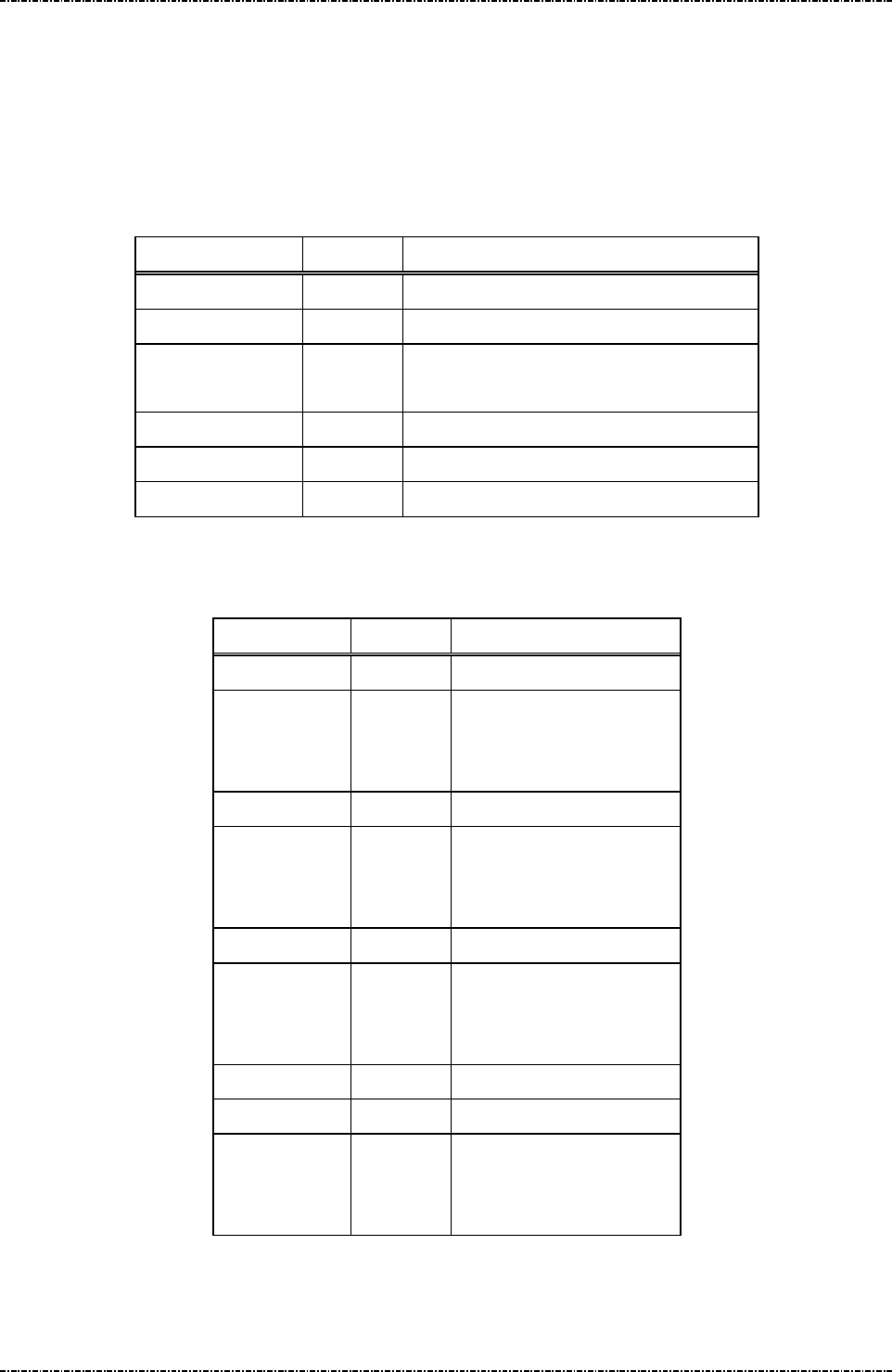
PIN Pad 791 Programmer’s Manual (PCI POS-A) UDN PM0103-U Rev. 06
Section 7 – Contactless EMV Level 2 transaction messages 2015-04-20
Page132
Uniform Industrial Corp. Proprietary and Confidential Total 342 pages
Message T59 PCD Config Data Query Message
Format: <STX>T59[Config Type][control] <ETX>[LRC]
Message length: Fixed 7 bytes.
Usage: Get the group ID of PCD application data or CA public key stored in PIN pad.
Message element:
Field Length Value and description
<STX> 1 <02>
T59 3 Message ID
[Config Type] 1 1: All the IDs of PCD public key.
2: All the IDs of PCD application data.
[control] 1 (option)'0': Ready for next packet.
<ETX> 1 <03>
[LRC] 1 Checksum
Message flow:
HOST Direction PIN pad
Message T59
<ACK> (Good LRC)
<NAK> (Bad LRC)
<EOT> (after 3 NAKs)
Message T5A(Result = 3)
<ACK>/
<NAK>/
<EOT>
Message T59
<ACK> (Good LRC)
<NAK> (Bad LRC)
<EOT> (after 3 NAKs)
… … …
Message T5A(Result = 0)
<ACK>/
<NAK>/
<EOT>

PIN Pad 791 Programmer’s Manual (PCI POS-A) UDN PM0103-U Rev. 06
Section 7 – Contactless EMV Level 2 transaction messages 2015-04-20
Page133
Uniform Industrial Corp. Proprietary and Confidential Total 342 pages
Message T5A Response of PCD Config Data Query Message
Format: <STX>T5A<SUB>[Result]<SUB>[ID List]<ETX>[LRC]
Message length: Variable.
Usage: Get the group ID of EMV application data or CA public key stored in PIN pad.
Message element:
Field Length Value and description
<STX> 1 <02>
T5A 3 Message ID
<SUB> 1 <1A>
Result 1 0: There is data in identified data type.
1: No data in identified data type.
2: Format Error.
3: Arrange exceed.
<SUB> 1 <1A>, Optional if Result is 0, 3.
ID List Var Optional, if Result is 0, 3.
[LRC] 1 Checksum
[ID List]: The concatenation of IDs. There is a <FS> between each ID.
Ex. [ID List] = A00000000390<FS> A000000004F8<FS> A000000004F5 ( Config Type = 1 )
[ID List] = A0000000041010<FS>B0123456781234<FS> A000000010 ( Config Type = 2 )
Message flow: Please refer to message T59.
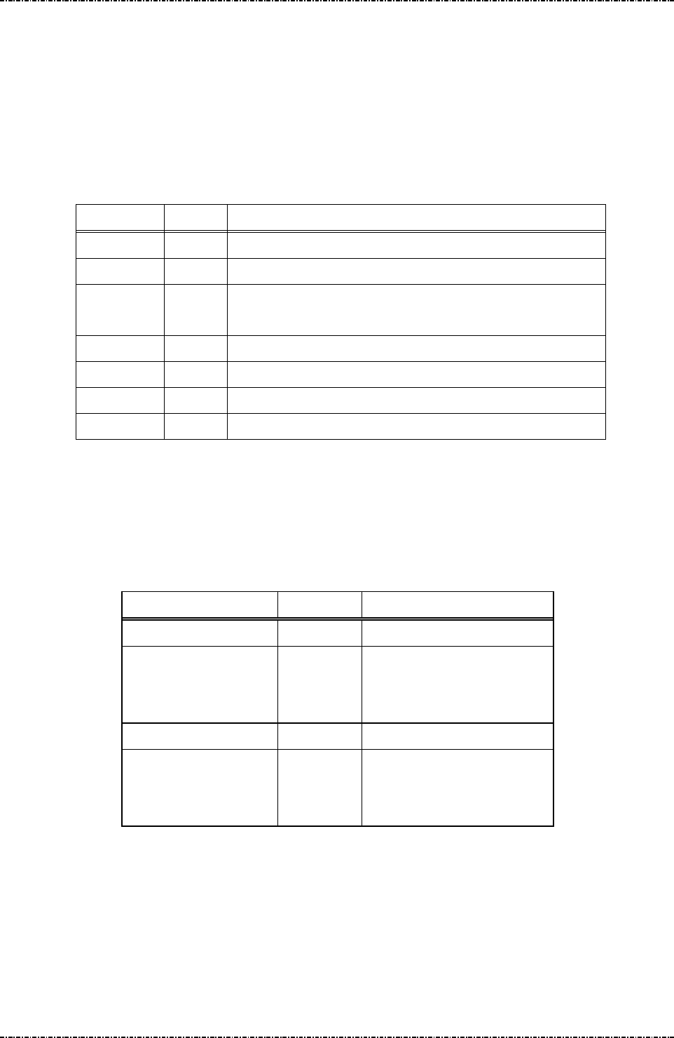
PIN Pad 791 Programmer’s Manual (PCI POS-A) UDN PM0103-U Rev. 06
Section 7 – Contactless EMV Level 2 transaction messages 2015-04-20
Page134
Uniform Industrial Corp. Proprietary and Confidential Total 342 pages
Message T5B Delete PCD Configuration Data Message.
Format: <STX>T5B[Config Type]<SUB>[ID List]<ETX>[LRC]
Message length: Variable.
Usage: Host can use this command to delete PCD application configuration data or CA
public key in PIN pad, this command can be sent many times.
Message element:
Field Length
Value and description
<STX> 1 <02>
T5B 3 Message ID
Config Type
1 1: CA public key.
2: EMV application data.
<SUB> 1 <1A>
ID List Var List of ID that will be erased.
<ETX> 1 <03>
[LRC] 1 Checksum
[ID List]: The concatenation of IDs. There is a <FS> between each ID.
Ex. [ID List] = A00000000390<FS> A000000004F8<FS> A000000004F5 ( Config Type = 1 )
[ID List] = A0000000041010<FS>B0123456781234<FS> A000000010 ( Config Type = 2 )
Message flow:
HOST Direction PIN pad
Message T5B
<ACK> (Good LRC)
<NAK> (Bad LRC)
<EOT> (after 3 NAKs)
Message T5C
<ACK> (Good LRC)
<NAK> (Bad LRC)
<EOT> (after 3 NAKs)

PIN Pad 791 Programmer’s Manual (PCI POS-A) UDN PM0103-U Rev. 06
Section 7 – Contactless EMV Level 2 transaction messages 2015-04-20
Page135
Uniform Industrial Corp. Proprietary and Confidential Total 342 pages
Message T5C Response of Delete PCD Configuration Data Message.
Format: <STX>T5C<SUB>[Status]<SUB>[Del Result]<ETX>[LRC]
Message length: Variable.
Usage: The response message of command T5B.
Message element:
Field Length Value and description
<STX> 1 <02>
T5C 3 Message ID
<SUB> 1 <1A>
Status 1 0: Delete OK
1: Fatal Error
2: Format error.
<SUB> 1 <1A>, Optional, if Status is 0.
Del Result var The results of delete operation on indicated ID
<ETX> 1 <03>
[LRC] 1 Checksum
[Del Result]: It’s the concatenation of results for delete operation on indicated ID. There is a <FS>
between each result. If the delete operation is successfully (When PIN pad finds
out the matched one and delete it successfully), the result is 0. If there is no such ID as
terminal specified, the result is 1.
Ex. Terminal issues message T5B to erase EMV application data with ID “A0000000102020”,
“A0000020” and “A0000000103030”. PIN pad now keeps EMV application data with ID
“A0000000103030” only.
The data in [Del Result] field will be “1<FS>1<FS>0”.
Message flow: Please refer to message T5B.
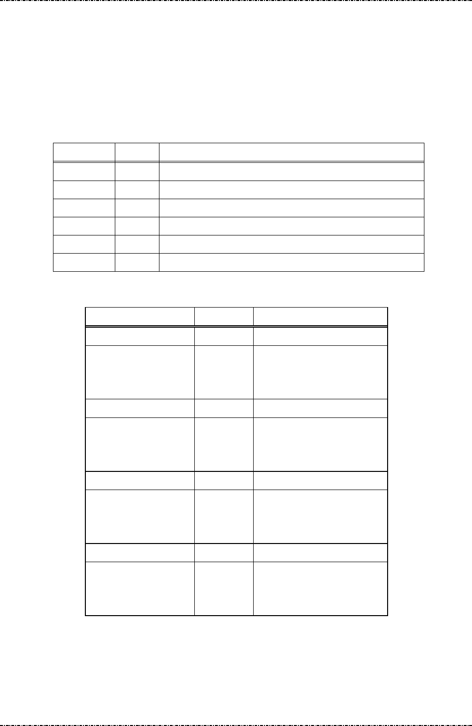
PIN Pad 791 Programmer’s Manual (PCI POS-A) UDN PM0103-U Rev. 06
Section 7 – Contactless EMV Level 2 transaction messages 2015-04-20
Page136
Uniform Industrial Corp. Proprietary and Confidential Total 342 pages
Message T5D PCD House Keeping Message.
Format: <STX>T5D<SUB>[Config Type]<ETX>[LRC]
Message length: Variable.
Usage: Host can use this command to call PCD housekeeping in PIN pad, this command can
be sent many times.
Message element:
Field Length
Value and description
<STX> 1 <02>
T5B 3 Message ID
<SUB> 1 <1A>
Config Type
1 1: Paypass.
<ETX> 1 <03>
[LRC] 1 Checksum
Message flow:
HOST Direction PIN pad
Message T5D
<ACK> (Good LRC)
<NAK> (Bad LRC)
<EOT> (after 3 NAKs)
Message T5E10
<ACK> (Good LRC)
<NAK> (Bad LRC)
<EOT> (after 3 NAKs)
Message T5D
<ACK> (Good LRC)
<NAK> (Bad LRC)
<EOT> (after 3 NAKs)
Message T5E10 or T5E1F
<ACK> (Good LRC)
<NAK> (Bad LRC)
<EOT> (after 3 NAKs)

PIN Pad 791 Programmer’s Manual (PCI POS-A) UDN PM0103-U Rev. 06
Section 7 – Contactless EMV Level 2 transaction messages 2015-04-20
Page137
Uniform Industrial Corp. Proprietary and Confidential Total 342 pages
Message T5E Response of PCD House Keeping Message.
Format: <STX>T5E<SUB>[Status][Result]<ETX>[LRC]
Message length: Variable.
Usage: The response message of command T5D.
Message element:
Field Length Value and description
<STX> 1 <02>
T5E 3 Message ID
<SUB> 1 <1A>
Status 1 0: Unkown type
1: Paypass
Result var 0: Empty or not expired.
1: Clear data
2: Fatal error.
F: Format error.
<ETX> 1 <03>
[LRC] 1 Checksum
Message flow: Please refer to message T5D.

PIN Pad 791 Programmer’s Manual (PCI POS-A) UDN PM0103-U Rev. 06
Section 7 – Contactless EMV Level 2 transaction messages 2015-04-20
Page138
Uniform Industrial Corp. Proprietary and Confidential Total 342 pages
Message T61 Start Transaction
Format: <STX>T61<SUB>[AmtAuth]<SUB>[AmtOther]<SUB>
[CurExponent][CurCode]<SUB>[TranType]<SUB>[TranInfo]<SUB>
[Account Type]<SUB>[Force Online]<SUB>[Encrypted Session key]
<ETX>[LRC]
Message length: Variable.
Usage: After receive this message command T61, PIN pad will perform an completed EMV
transaction flow (the flow will cover ‘Initiate Application’ through ‘Completion’, see EMV
Contactless Specifications 2.4, book A, chap 5.3, figure 5-2 - Logical Architecture). PIN
pad will send the message T62 (Start Transaction Response) to host.
Message element:
Field Length
Value and description
<STX> 1 <02>
T61 3 Message ID
<SUB> 1 <1A>
[AmtAuth] 12 Hexadecimal, Amount Authrozied,
will be stored at tag ‘0x9f02’
<SUB> 1 <1A>
[AmtOther] 12 Hexadecimal, Amount Other, will be
stored at tag ‘0x9f03’
<SUB> 1 <1A>
[CurExponent] 1 Hexadecimal, stored at tag ‘0x5F36’
[CurCode] 3 Hexadecimal, stored at tag ‘0x5F2A’.
For example, USD$ = 0x840
<SUB> 1 <1A>
[TranType] 2 Hexadecimal, Transaction Type, will
be stored at tag ‘0x9C’
<SUB> 1 <1A>
[TranInfo] 2 Transaction Info, will be stored at tag
‘0x60000001’
<SUB> 1 <1A>
[Account Type] 2 Account Type, stored at tag ‘0x5F57’
<SUB> 1 <1A>
[Force Online] 1 1: Force Online, only valid if this
terminal has the capability of support
online authorization.
<SUB> 1 <1A>

PIN Pad 791 Programmer’s Manual (PCI POS-A) UDN PM0103-U Rev. 06
Section 7 – Contactless EMV Level 2 transaction messages 2015-04-20
Page139
Uniform Industrial Corp. Proprietary and Confidential Total 342 pages
[Encrypted
Session key]
16 or
32
Optional, DES or TDES session key
that used to encrypt PIN entry when
CVM ask online PIN verify.
If the CVM ask online PIN verify but
this session key does not input, PIN
pad will ignore the PIN entry request
and indicate that no PIN is entered in
the TVR register.
<SUB> 1 <1A>,Optional, only if [DO] is existed
DO Var. Data Object, format as below
<ETX> 1 <03>
[LRC] 1 Checksum
Message flow:
HOST Direction PIN Pad
Message T61
<ACK> (Good LRC)
<NAK> (Bad LRC)
<EOT> (after 3 NAKs)
Start Transaction Response.
Message T62
<ACK> (Good LRC)
<NAK> (Bad LRC)
<EOT> (after 3 NAKs)

PIN Pad 791 Programmer’s Manual (PCI POS-A) UDN PM0103-U Rev. 06
Section 7 – Contactless EMV Level 2 transaction messages 2015-04-20
Page140
Uniform Industrial Corp. Proprietary and Confidential Total 342 pages
Message T62 Start Transaction Response
Format: <STX>T62[Status][Reason][Err Message][Result]<ETX>[LRC]
Message length: Variable.
Usage: The message contains the transaction result on the smart card to be sent to terminal.
Message element:
Field Length
Value and description
<STX> 1 <02>
T62 3 Message ID
[Status] 1 0:OK; 1:Fail
[Reason] 1 Optional. (If Status = 1)
1:Fatal Error
2:Command Format Error
[Err Message] 8 Optional, if Reason = ‘1’Hex String
[Result] 2 Optional. (If Status = 0)
‘Y1’: Offline Approved,
‘Z1’: Offline Declined
‘Y3’: Unable to go online,
Offline Approved
‘Z3’: Unable to go online, Offline Decline.
‘Y4’: Online Approved
‘Z4’: Online Decline
‘Y7’: Offline Approved With Signature
‘Y8’: Unable to go online,
Offline Approved With Signature
‘Y9’: Online Approved With Signature
‘A1’: Online Authorize Request
‘B0’: Try another interface.
<ETX> 1 <03>
[LRC] 1 Checksum
Note: If the [Result] is ‘A1’, then terminal should send online authorization request to issuer host; and
after done, terminal shall send message T71 to PIN pad to continue transaction.
Message flow: Please refer to message T61.

PIN Pad 791 Programmer’s Manual (PCI POS-A) UDN PM0103-U Rev. 06
Section 7 – Contactless EMV Level 2 transaction messages 2015-04-20
Page141
Uniform Industrial Corp. Proprietary and Confidential Total 342 pages
Message T63 Get Transaction Result’s Data
Format: <STX>T63[control][DOL]<ETX>[LRC]
Message length: Var.
Usage: PIN pad will retrieve the data that list on the DOL after EMV transaction done. PIN pad
will send the message T64 (Get Transaction Result’s Data Response) to host.
Message element:
Field Length Value and description
<STX> 1 <02>
T63 3 Message ID
[control] 1 (optional)
'0': Ready for next packet, [DOL] is
ignored.
[DOL] Var Data Object List, each object is expressed
by tag number, and <SUB> is used to
delimit each object. For example,
9F12<SUB>9A<SUB>9F02<SUB>….
<ETX> 1 <03>
[LRC] 1 Checksum
Message flow:
HOST Direction PIN Pad
Message T63
<ACK> (Good LRC)
<NAK> (Bad LRC)
<EOT> after 3 NAKs
Get Transaction Result’s Data
Response.
Message T64
<ACK> (Good LRC)
<NAK> (Bad LRC)
<EOT> (after 3 NAKs)

PIN Pad 791 Programmer’s Manual (PCI POS-A) UDN PM0103-U Rev. 06
Section 7 – Contactless EMV Level 2 transaction messages 2015-04-20
Page142
Uniform Industrial Corp. Proprietary and Confidential Total 342 pages
Message T64 Get Transaction Result’s Data Response
Format: <STX>T64[Pkt NO.][Total Pkt][DO]<ETX>[LRC]
Message length: Var.
Usage: The message contains the transaction result’s data to be sent to host.
Message element:
Field Length Value and description
<STX> 1 <02>
T64 3 Message ID
[Pkt NO.] 1 Decimal. Packet sequence number (1 ~ 9).
[Total Pkt] 1 Decimal. Total packets (1~9).
[DO] Var. Data Object, each data object is expressed
by TLV format with an <FS> delimit in
each field, and <SUB> is used to delimit
each object. For example:
9F12<FS>0F<FS>CREDITO DE
VISA<SUB>9A<FS>06<FS>050806<SU
B>…….
<ETX> 1 <03>
[LRC] 1 Checksum
Data Object:
PIN pad will return series of data object that list on the [DOL] field in the message T64 with TLV (tag ||
length|| value) format as below:
[EMV Tag Number (2 ~ 8 byte)] <FS> [Length (2byte)] <FS> [Value] <SUB>
[EMV Tag Number (2 ~ 8 byte)] <FS> [Length (2byte)] <FS> [Value] <SUB>
. . . . . . . .
[EMV Tag Number (2 ~ 8 byte)] <FS> [Length (2byte)] <FS> [Value].
Note: When PIN Pad response these data object, it will convert these value from binary value to hex
decimal string if the data object format is “b” or “cn” or “n”.
Message flow: Please refer to message T63.
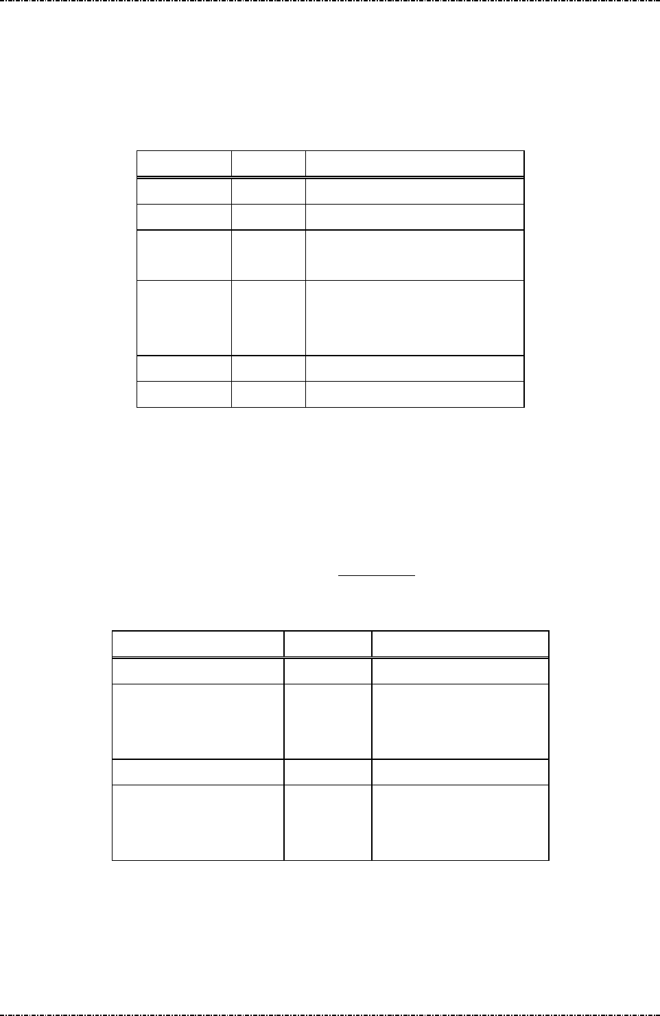
PIN Pad 791 Programmer’s Manual (PCI POS-A) UDN PM0103-U Rev. 06
Section 7 – Contactless EMV Level 2 transaction messages 2015-04-20
Page143
Uniform Industrial Corp. Proprietary and Confidential Total 342 pages
Message T65 Get Online authorization Data
Format: <STX>T65[Data type][control]<ETX>[LRC]
Message length: Variable 7 to 8 bytes.
Usage: Issue this message to get data (EMV) for online authorization.
Message element:
Field Length Value and description
<STX> 1 <02>
T65 3 Message ID
[Data type] 1 0 : Data record
1 : Discretionary data
[control] 1 (optional)
'0': Ready for next packet, [Data
type] is ignored.
<ETX> 1 <03>
[LRC] 1 Checksum
While the EMV transaction must be authorized online, terminal shall issue message T65 to get the
necessary data for online authorization from PIN pad. And PIN pad will wait terminal to send one
message T71 to tell the PIN pad the go online authorization result
PIN pad will search the corresponding values according to this tag list and return it at message T66 after
receive message T65 from terminal. Please refer to Appendix G for more details.
Message flow:
HOST Direction PIN Pad
Message T65
<ACK> (Good LRC)
<NAK> (Bad LRC)
<EOT> (after 3 NAKs)
Message T66
<ACK> (Good LRC)
<NAK> (Bad LRC)
<EOT> (after 3 NAKs)

PIN Pad 791 Programmer’s Manual (PCI POS-A) UDN PM0103-U Rev. 06
Section 7 – Contactless EMV Level 2 transaction messages 2015-04-20
Page144
Uniform Industrial Corp. Proprietary and Confidential Total 342 pages
Message T66 Response of Get Online authorization Data message
Format: <STX>T66[Pkt NO.][Total Pkt][online authorization data]<ETX>[LRC]
Message length: var.
Usage: Return online authorization data to terminal.
Message element:
Field Length Value and description
<STX> 1 <02>
T66 3 Message ID
[Pkt NO.] 1 Decimal. Packet sequence number (1 ~ 9)
[Total Pkt] 1 Decimal. Total packets (1~9).
[Online authorization data] Var. Hex string.
Optional, if this transaction needs to be
authorized online.
<ETX> 1 <03>
[LRC] 1 Checksum
Online authorization data:
PIN pad return series of data object with TLV (tag || length|| value) format as below:
[EMV Tag Number (2 ~ 8 byte)] || [Length (2byte)] || [Value]
[EMV Tag Number (2 ~ 8 byte)] || [Length (2byte)] || [Value]
. . . . . . . .
[EMV Tag Number (2 ~ 8 byte)] || [Length (2byte)] || [Value].
PIN pad can return at maximum 256 bytes of data as one record, the right part of data will be ignored if
the length record is greater than 256 byte.
When PIN pad response these data object, it will convert these value from binary value to hex decimal
string if the data object format is “b” or “cn” or “n”. For example, the data of one record is 0x9F02 || 06 ||
000000001100 || 5A || 10 || 11223344556677889900AABBCCDDEEFF, terminal will see
“9F02060000000011005A1011223344556677889900AABBCCDDEEFF”.
Message flow: Please refer to message T65

PIN Pad 791 Programmer’s Manual (PCI POS-A) UDN PM0103-U Rev. 06
Section 7 – Contactless EMV Level 2 transaction messages 2015-04-20
Page145
Uniform Industrial Corp. Proprietary and Confidential Total 342 pages
Message T6C Cancel PCD Transaction
Format: <STX>T6C<ETX>[LRC]
Message length: Fixed 6 bytes.
Usage: This message used to cancel the transaction for contactless card.
Message element:
Field Length Value and description
<STX> 1 <02>
T6C 3 Message ID
<ETX> 1 <03>
[LRC] 1 Checksum
Message flow:
HOST Direction PIN pad
Message T6C
<ACK> (Good LRC)
<NAK> (Bad LRC)
<EOT> (after 3 NAKs)

PIN Pad 791 Programmer’s Manual (PCI POS-A) UDN PM0103-U Rev. 06
Section 7 – Contactless EMV Level 2 transaction messages 2015-04-20
Page146
Uniform Industrial Corp. Proprietary and Confidential Total 342 pages
Message T71 Send PCD Online Authorized Code
Format: <STX>T71[Online Res]<SUB>[ARC]<SUB>[IAD]<ETX>[LRC]
Message length: Fixed 7 or 16 bytes.
Usage: After receive this message T71, PIN pad will continue to perform the EMV transaction
flow if the previous T62 response result is ‘A1’ (online authorized request, see EMV
Contactless Specifications v2.4). PIN pad will response the message T62 (Start
Transaction Response) to this T71 to host.
Message element:
Field Length Value and description
<STX> 1 <02>
T71 3 Message ID
[Online Res] 1 ‘0’: Unable to go online
<ETX> 1 <03>
[LRC] 1 Checksum
OR
Field Length Value and description
<STX> 1 <02>
T71 3 Message ID
[Online Res] 1 ‘1’: Get Online Authorize Response,
<SUB> 1 <1A>
[ARC] 2 Optional, Authorisation Response code,
ASCII (0~9, A~Z).
<SUB> 1 <1A>
[IAD] 16~32 Optional, Issuer Authentication Data,
Hex string.
if there is IAD response from remote
host , terminal shall send this to PIN
pad.
<ETX> 1 <03>
[LRC] 1 Checksum

PIN Pad 791 Programmer’s Manual (PCI POS-A) UDN PM0103-U Rev. 06
Section 7 – Contactless EMV Level 2 transaction messages 2015-04-20
Page147
Uniform Industrial Corp. Proprietary and Confidential Total 342 pages
Message flow:
HOST Direction PIN pad
Message T71
<ACK> (Good LRC)
<NAK> (Bad LRC)
<EOT> (after 3 NAKs)
Start Transaction Response.
Message T62
<ACK> (Good LRC)
<NAK> (Bad LRC)
<EOT> (after 3 NAKs)

PIN Pad 791 Programmer’s Manual (PCI POS-A) UDN PM0103-U Rev. 06
Section 7 – Contactless EMV Level 2 transaction messages 2015-04-20
Page148
Uniform Industrial Corp. Proprietary and Confidential Total 342 pages
Message T73 Send Issuer Script Command
Format: <STX>T73[IS]<ETX>[LRC]
Message length: Var.
Usage: PIN pad performs the Issuer script processing as in EMV transaction flow after
received this command from the host those are the response message when doing
online authorization. This command can be send many times if too many script
commands need to be processed, but the last one should be send before T71
command.
Message element:
Issuer Script Format: (see EMV Contactless Specifications v2.4)
T L T L Script ID Commands
‘71’ or
‘72’
Including
Script ID,
tags,
lengths
‘9F18’ ‘04’ Identifier (4 bytes)
Issuer Script
Command Format
(see below)
Issuer Script Command Format: (see EMV Contactless Specifications v2.4)
T1 L1 V1 T2 L2 V2 T3 L3 V3 Tx Lx Vx
‘86’ L(V1)
Cmd
‘86’ L(V2)
Cmd
‘86’ L(V3)
Cmd
‘86’ L(Vx)
cmd
Field Length Value and description
<STX> 1 <02>
T73 3 Message ID
IS Var. Issuer Script, format as follow. Hex string.
<ETX> 1 <03>
[LRC] 1 Checksum

PIN Pad 791 Programmer’s Manual (PCI POS-A) UDN PM0103-U Rev. 06
Section 7 – Contactless EMV Level 2 transaction messages 2015-04-20
Page149
Uniform Industrial Corp. Proprietary and Confidential Total 342 pages
Message T75 Revocation List Setup
Format: <STX>T75<SUB>[RID][SN][PKI]<ETX>[LRC]
Message length: Fixed 25 bytes
Usage: Host can use this command to send revocation key information to PIN pad, this
command can be sent many times. PIN pad will save those information inside and
check those information when do the transaction. PIN pad will send the message T76
(Revocation List Setup Response) to host.
Message element:
Field Length Value and description
<STX> 1 <02>
T75 3 Message ID
<SUB> 1 Separator
[RID] 10 The RID for revocated public key. Present in hexstring.
[SN] 6 The serial number of the revocated public key.
Present in
hexstring.
[PKI] 2
The public key index of the revocated key. Present in
hexstring.
<ETX> 1 <03>
[LRC] 1 Checksum
Example:
Revocation list information
RID: A0 00 00 00 03
SN: 00 00 01
PKI: 51
<STX>T75<SUB> A00000000300000151<ETX>[LRC]
Message flow:
HOST Direction PIN pad
Message T75
<ACK> (Good LRC)
<NAK> (Bad LRC)
<EOT> (after 3 NAKs)
Message T76
<ACK> (Good LRC)
<NAK> (Bad LRC)
<EOT> (after 3 NAKs)

PIN Pad 791 Programmer’s Manual (PCI POS-A) UDN PM0103-U Rev. 06
Section 7 – Contactless EMV Level 2 transaction messages 2015-04-20
Page150
Uniform Industrial Corp. Proprietary and Confidential Total 342 pages
Message T76 Revocation List Setup Response
Format: <STX>T76[Res][Reason][Err Msg]<ETX>[LRC]
Message length: Variable.
Usage: The response message of command T75.
Message element:
Field Length Value and description
<STX> 1 <02>
T76 3 Message ID
[Res] 1 ‘0’: Ok,
‘1’: Fail
[Reason] 1 <Optional, if Res = ‘1’>
‘1’: Fatal error
‘2’: Invalid Data format
‘3’: Revocation list is full
‘4’: The added info exists
[Err Message] 8 Optional, if Reason = ‘1’, Hex decimal string
<ETX> 1 <03>
[LRC] 1 Checksum
Message flow: Please refer to message T75.
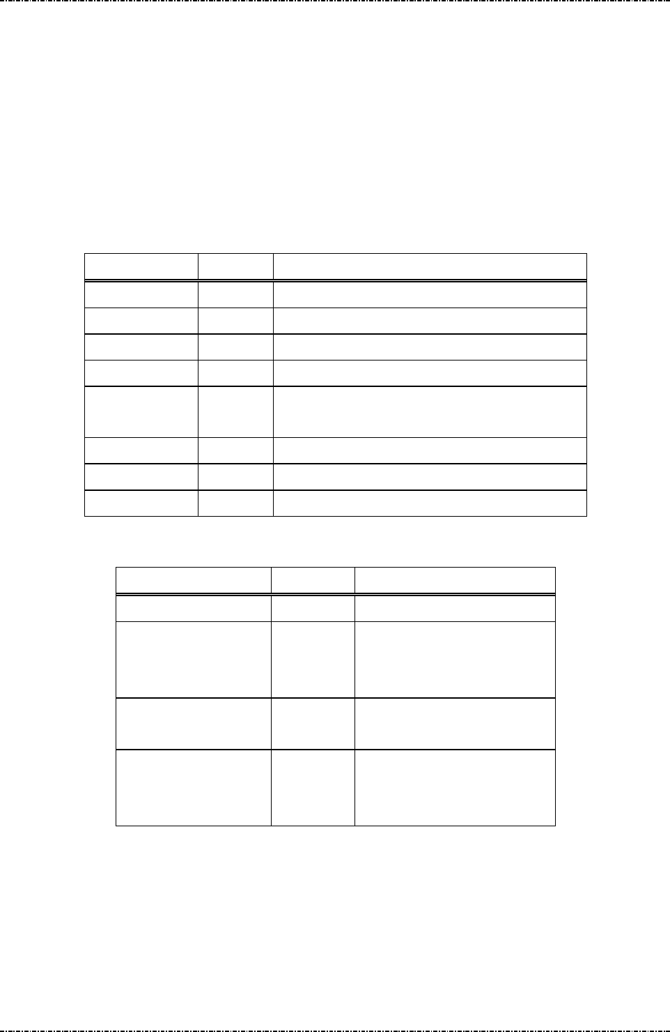
PIN Pad 791 Programmer’s Manual (PCI POS-A) UDN PM0103-U Rev. 06
Section 7 – Contactless EMV Level 2 transaction messages 2015-04-20
Page151
Uniform Industrial Corp. Proprietary and Confidential Total 342 pages
Message T77 Exception List Setup
Format: <STX>T77<SUB>[PAN][<SUB>[PAN Seq. No.]<ETX>[LRC]
Message length: Variable.
Usage: Host can use this command to send the exception pan to PIN pad. PIN pad will save
the information inside and check them when do the transaction. Once the transaction
pan is on the exception list, the transaction will be terminated. PIN pad will send the
message T78 (Exception List Setup Response) to host when it add an exception file.
Message element:
Field Length Value and description
<STX> 1 <02>
T77 3 Message ID
<SUB> 1 Separator
[PAN] up to 19 Primary Account Number with numeric format
<SUB> 1 Separator. This is optional, exist if PAN Seq. No.
exists.
[PAN Seq. No.]
2 PAN Sequence Number, this is an optional data.
<ETX> 1 <03>
[LRC] 1 Checksum
Message flow:
HOST Direction PIN pad
Message T77
<ACK> (Good LRC)
<NAK> (Bad LRC)
<EOT> (after 3 NAKs)
Exception List Setup Response
Message T78
<ACK> (Good LRC)
<NAK> (Bad LRC)
<EOT> (after 3 NAKs)
Command Example:
PAN: 47 61 73 90 01 01 00 10
<STX>T77<SUB>4761739001010010<ETX><LRC>
PAN: 37 37 37 34 56 78 90 4
PAN Seq. No.: 00
<STX>T77<1A>373737345678904<1A>00<ETX><LRC>

PIN Pad 791 Programmer’s Manual (PCI POS-A) UDN PM0103-U Rev. 06
Section 7 – Contactless EMV Level 2 transaction messages 2015-04-20
Page152
Uniform Industrial Corp. Proprietary and Confidential Total 342 pages
Message T78 Exception List Setup Response
Format: <STX>T78[Resp][Reason][Err Msg]<ETX>[LRC]
Message length: Variable.
Usage: The response message of command T77.
Message element:
Field Length Value and description
<STX> 1 <02>
T78 3 Message ID
[Resp] 1 ‘0’: Ok,
‘1’: Fail
[Reason] 1 Option if [Resp] is ‘1’,
‘1’: Fatal Error
‘2’: Format Error
‘3’: Exception List is full
‘4’: PAN exists
[Err Message] 8 Optional, if Reason = ‘1’,
Hex String
<ETX> 1 <03>
[LRC] 1 Checksum
Message flow: Please refer to message T77

PIN Pad 791 Programmer’s Manual (PCI POS-A) UDN PM0103-U Rev. 06
Section 7 – Contactless EMV Level 2 transaction messages 2015-04-20
Page153
Uniform Industrial Corp. Proprietary and Confidential Total 342 pages
Overall Contactless EMV Level 2 transaction flow reference
PIN pad provide one complete EMV Level 2 transaction with online or offline approval by various command
flow. To force PIN pad to leave this command flow, you can either press the [CANCEL] key or send one T6C
command to PIN pad.
Ref. 1 Packet command flow for transaction with offline approval
HOST Direction PIN pad
T61 (Start Transaction)
T62 (Start Transaction Response)
[Result] = ‘Y1’ or ‘Z1’
T65 (Get online data from PIN pad)
T66 (Online authorization data response)
T63 (Get Transaction Result’s Data)
T64 (Get Transaction Result’s Data
Response)

PIN Pad 791 Programmer’s Manual (PCI POS-A) UDN PM0103-U Rev. 06
Section 7 – Contactless EMV Level 2 transaction messages 2015-04-20
Page154
Uniform Industrial Corp. Proprietary and Confidential Total 342 pages
Ref. 2 Packet command flow for transaction with online approval
HOST Direction PIN Pad
T61 (Start Transaction)
T62 (Start Transaction Response)
[Result] = ‘A1’
T65 (Get online data from PIN pad)
T66 (Online authorization data response)
T63 (Get Transaction Result’s Data)
T64 (Get Transaction Result’s Data
Response)
Go Online
T71 (Send Online Authorized Code)
T62 (Start Transaction Response)
T63 (Get Transaction Result’s Data)
T64 (Get Transaction Result’s Data
Response)

PIN Pad 791 Programmer’s Manual (PCI POS-A) UDN PM0103-U Rev. 06
Section 8 – MIFARE card messages 2015-04-20
Page155
Uniform Industrial Corp. Proprietary and Confidential Total 342 pages
Section 8 MIFARE card messages
This chapter describe the command of MIFARE card. The PIN pad supports MIFARE classic, Ultralight
and DESFire card. All MIFARE card are compliant to the ISO/IEC 14443-1, 2 and 3. The MIFARE
DESFire card support ISO/IEC 14443-4 protocol (also called “T=CL” protocol).
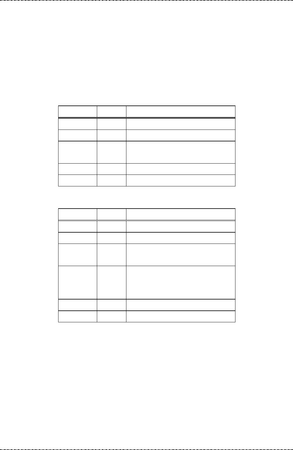
PIN Pad 791 Programmer’s Manual (PCI POS-A) UDN PM0103-U Rev. 06
Section 8 – MIFARE card messages 2015-04-20
Page156
Uniform Industrial Corp. Proprietary and Confidential Total 342 pages
Message P01 Enable/Disable MIFARE
Format: <STX>P01[Flag]<EXT>[LRC] (request frame)
<STX>P01[Result][Reason]<ETX>[LRC] (response frame)
Message length: Fixed 7 bytes for request frame
Variable for response frame.
Usage: Enable or Disable MIFARE.
Message element:
Request frame (HOST to PIN pad)
Field Length
Value and description
<STX> 1 <02>
P01 3 Message ID
[Flag] 1 ‘0’: Disable MIFARE.
‘1’: Enable MIFARE.
<ETX> 1 <03>
[LRC] 1 Checksum
Response frame (PIN pad to HOST)
Field Length
Value and description
<STX> 1 <02>
P01 3 Message ID
[Result] 1 ‘0’: Success.
‘1’: Fail.
[Reason] 1 Optional: if [Result] = ‘1’
‘1’: Format error.
‘2’: Sequence error.
<ETX> 1 <03>
[LRC] 1 Checksum

PIN Pad 791 Programmer’s Manual (PCI POS-A) UDN PM0103-U Rev. 06
Section 8 – MIFARE card messages 2015-04-20
Page157
Uniform Industrial Corp. Proprietary and Confidential Total 342 pages
Message flow:
HOST Direction
PIN pad
Message P01 (request
frame)
<ACK> (Good LRC)
<NAK> (Bad LRC)
<EOT> (after 3 NAKs)
Message P01 (response
frame)
<ACK> (Good LRC)
<NAK> (Bad LRC)
<EOT> (after 3 NAKs)
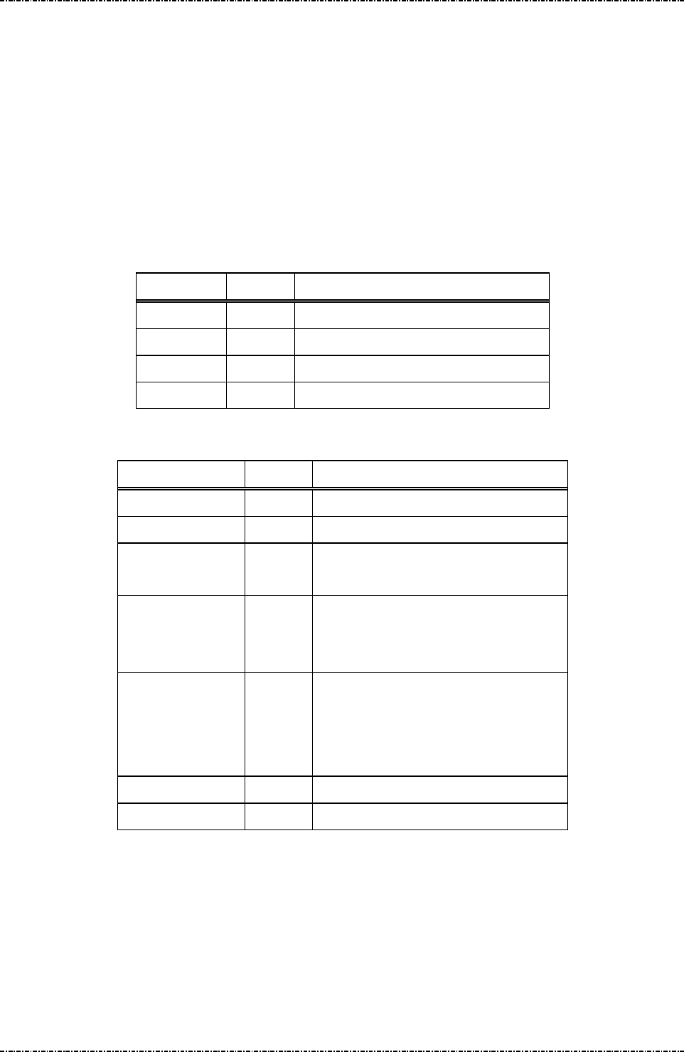
PIN Pad 791 Programmer’s Manual (PCI POS-A) UDN PM0103-U Rev. 06
Section 8 – MIFARE card messages 2015-04-20
Page158
Uniform Industrial Corp. Proprietary and Confidential Total 342 pages
Message P02 Query MIFARE Presence
Format: <STX>P02<ETX>[LRC] (request frame)
<STX>P02[Result][ATQA][Reason]<ETX>[LRC]
(response frame)
Message length: Fixed 6 bytes for request frame
Variable for response frame.
Usage: Send WUPA command to contact less card.
Message element:
Request frame (HOST to PIN pad)
Field Length
Value and description
<STX> 1 <02>
P02 3 Message ID
<ETX> 1 <03>
[LRC] 1 Checksum
Response frame (PIN pad to HOST)
Field Length
Value and description
<STX> 1 <02>
P02 3 Message ID
[Result] 1 ‘0’: Success.
‘1’: Fail.
[ATQA] 4 Optional: if [Result] = ‘0’
ATQA: 4 bytes.
Format: hexadecimal string.
[Reason] 1 Optional: if [Result] = ‘1’
‘1’: Format error.
‘2’: Sequence error.
‘3’: Card not exists.
<ETX> 1 <03>
[LRC] 1 Checksum

PIN Pad 791 Programmer’s Manual (PCI POS-A) UDN PM0103-U Rev. 06
Section 8 – MIFARE card messages 2015-04-20
Page159
Uniform Industrial Corp. Proprietary and Confidential Total 342 pages
Message flow:
HOST Direction
PIN pad
Message P02 (request
frame)
<ACK> (Good LRC)
<NAK> (Bad LRC)
<EOT> (after 3 NAKs)
Message P02 (response
frame)
<ACK> (Good LRC)
<NAK> (Bad LRC)
<EOT> (after 3 NAKs)
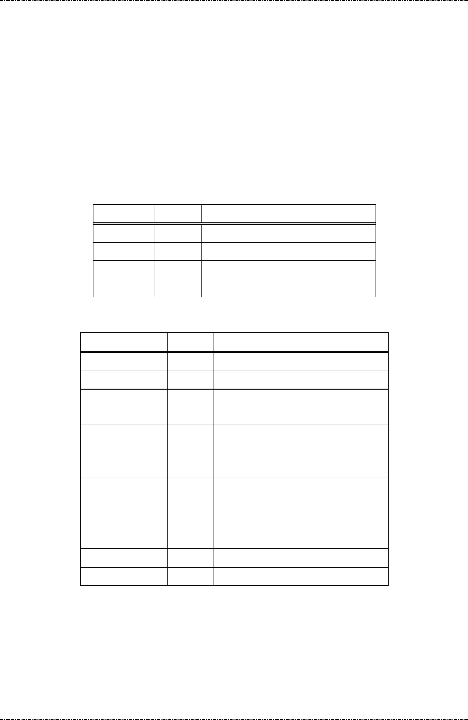
PIN Pad 791 Programmer’s Manual (PCI POS-A) UDN PM0103-U Rev. 06
Section 8 – MIFARE card messages 2015-04-20
Page160
Uniform Industrial Corp. Proprietary and Confidential Total 342 pages
Message P03 MIFARE Anti-collision
Format: <STX>P03<ETX>[LRC] (request frame)
<STX>P03[Result][UID][Reason]<ETX>[LRC]
(response frame)
Message length: Fixed 6 bytes for request frame
Variable for response frame.
Usage: This command is used to get the card’s UID. When many cards in RFID field, PIN pad
will get one card’s UID.
Message element:
Request frame (HOST to PIN pad)
Field Length
Value and description
<STX> 1 <02>
P03 3 Message ID
<ETX> 1 <03>
[LRC] 1 Checksum
Response frame (PIN pad to HOST)
Field Length
Value and description
<STX> 1 <02>
P03 3 Message ID
[Result] 1 ‘0’: Success.
‘1’: Fail.
[UID] Var. Optional: if [Result] = ‘0’
The UID length is 8, 14 or 20 bytes.
Format: hexadecimal string.
[Reason] 1 Optional: if [Result] = ‘1’
‘1’: Format error.
‘2’: Sequence error.
‘3’: Anti collision fail.
<ETX> 1 <03>
[LRC] 1 Checksum

PIN Pad 791 Programmer’s Manual (PCI POS-A) UDN PM0103-U Rev. 06
Section 8 – MIFARE card messages 2015-04-20
Page161
Uniform Industrial Corp. Proprietary and Confidential Total 342 pages
Message flow:
HOST Direction
PIN pad
Message P03 (request
frame)
<ACK> (Good LRC)
<NAK> (Bad LRC)
<EOT> (after 3 NAKs)
Message P03 (response
frame)
<ACK> (Good LRC)
<NAK> (Bad LRC)
<EOT> (after 3 NAKs)

PIN Pad 791 Programmer’s Manual (PCI POS-A) UDN PM0103-U Rev. 06
Section 8 – MIFARE card messages 2015-04-20
Page162
Uniform Industrial Corp. Proprietary and Confidential Total 342 pages
Message P04 MIFARE Selection
Format: <STX>P04<ETX>[LRC] (request frame)
<STX>P04[Result][SAK][Reason]<ETX>[LRC]
(response frame)
Message length: Fixed 6 bytes for request frame
Variable for response frame.
Usage: Select one card to activate.
Message element:
Request frame (HOST to PIN pad)
Field Length
Value and description
<STX> 1 <02>
P04 3 Message ID
<ETX> 1 <03>
[LRC] 1 Checksum
Response frame (PIN pad to HOST)
Field Length
Value and description
<STX> 1 <02>
P04 3 Message ID
[Result] 1 ‘0’: Success.
‘1’: Fail.
[SAK] 2 Optional: if [Result] = ‘0’
The response of select command.
Format: hexadecimal string.
[Reason] 1 Optional: if [Result] = ‘1’
‘1’: Format error.
‘2’: Sequence error.
‘3’: Select fail.
<ETX> 1 <03>
[LRC] 1 Checksum

PIN Pad 791 Programmer’s Manual (PCI POS-A) UDN PM0103-U Rev. 06
Section 8 – MIFARE card messages 2015-04-20
Page163
Uniform Industrial Corp. Proprietary and Confidential Total 342 pages
Message flow:
HOST Direction
PIN pad
Message P04 (request
frame)
<ACK> (Good LRC)
<NAK> (Bad LRC)
<EOT> (after 3 NAKs)
Message P04 (response
frame)
<ACK> (Good LRC)
<NAK> (Bad LRC)
<EOT> (after 3 NAKs)
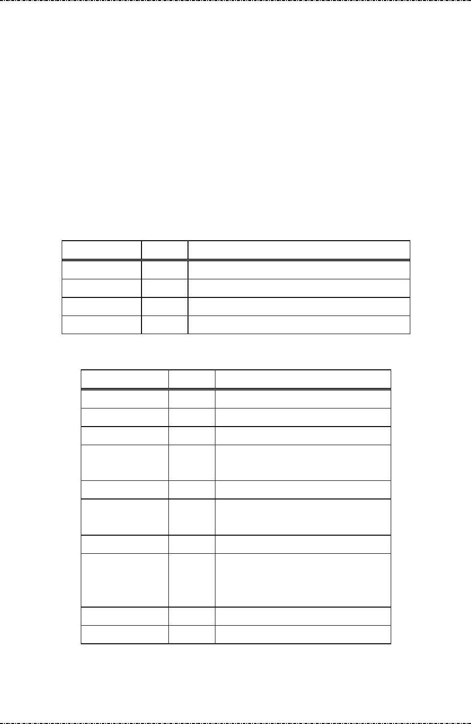
PIN Pad 791 Programmer’s Manual (PCI POS-A) UDN PM0103-U Rev. 06
Section 8 – MIFARE card messages 2015-04-20
Page164
Uniform Industrial Corp. Proprietary and Confidential Total 342 pages
Message P05 MIFARE Classic/Ultralight Card Activation
Format: <STX>P05<ETX>[LRC] (request frame)
<STX>P05[Result][ATQA]<FS>[SAK]<FS>[UID] <ETX>[LRC]
(response frame1)
<STX>P05[Result][Reason]<ETX>[LRC] (response frame2)
Message length: Fixed 6 bytes for request frame
Variable for response frame.
Usage: Activate MIFARE card. This command will send WUPA, Anti-collision and Selection
command to card.
Message element:
Request frame (HOST to PIN pad)
Field Length
Value and description
<STX> 1 <02>
P05 3 Message ID
<ETX> 1 <03>
[LRC] 1 Checksum
Response frame1 (PIN pad to HOST)
Field Length
Value and description
<STX> 1 <02>
P05 3 Message ID
[Result] 1 ‘0’: Success.
[ATQA] 4 ATQA: 4 bytes.
Format: hexadecimal string.
<FS> 1 Field separator.
[SAK] 2 The response of select command.
Format: hexadecimal string.
<FS> 1 Field separator.
[UID] Var. The card Unique Identifier. The UID
length is 8, 14 or 20 bytes.
Format: hexadecimal string.
<ETX> 1 <03>
[LRC] 1 Checksum

PIN Pad 791 Programmer’s Manual (PCI POS-A) UDN PM0103-U Rev. 06
Section 8 – MIFARE card messages 2015-04-20
Page165
Uniform Industrial Corp. Proprietary and Confidential Total 342 pages
Response frame2 (PIN pad to HOST)
Field Length
Value and description
<STX> 1 <02>
P05 3 Message ID
[Result] 1 ‘1’: Fail.
[Reason] 1 ‘1’: Format error.
‘2’: Sequence error.
‘3’: Card activate fail.
<ETX> 1 <03>
[LRC] 1 Checksum
Message flow:
HOST Direction
PIN pad
Message P05 (request
frame)
<ACK> (Good LRC)
<NAK> (Bad LRC)
<EOT> (after 3 NAKs)
Message P05 (response
frame)
<ACK> (Good LRC)
<NAK> (Bad LRC)
<EOT> (after 3 NAKs)
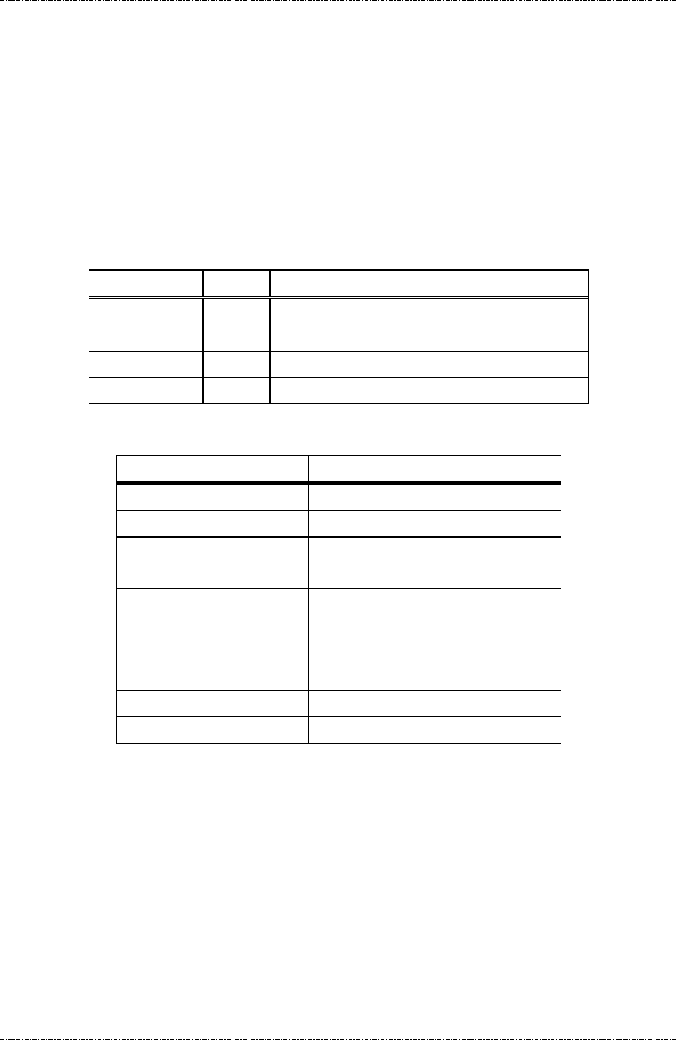
PIN Pad 791 Programmer’s Manual (PCI POS-A) UDN PM0103-U Rev. 06
Section 8 – MIFARE card messages 2015-04-20
Page166
Uniform Industrial Corp. Proprietary and Confidential Total 342 pages
Message P06 MIFARE Classic/Ultralight Card HALT
Format: <STX>P06<ETX>[LRC] (request frame)
<STX>P06[Result][Reason]<ETX>[LRC] (response frame)
Message length: Fixed 6 bytes for request frame
Fixed 7 or 8 bytes for response frame.
Usage: Send HALT command will deactivate card.
Message element:
Request frame (HOST to PIN pad)
Field Length
Value and description
<STX> 1 <02>
P06 3 Message ID
<ETX> 1 <03>
[LRC] 1 Checksum
Response frame (PIN pad to HOST)
Field Length
Value and description
<STX> 1 <02>
P06 3 Message ID
[Result] 1 ‘0’: Success.
‘1’: Fail.
[Reason] 1 Optional: if [Result] = ‘1’
‘1’: Format error.
‘2’: Sequence error.
‘3’: Card deactivate fail.
<ETX> 1 <03>
[LRC] 1 Checksum

PIN Pad 791 Programmer’s Manual (PCI POS-A) UDN PM0103-U Rev. 06
Section 8 – MIFARE card messages 2015-04-20
Page167
Uniform Industrial Corp. Proprietary and Confidential Total 342 pages
Message flow:
HOST Direction
PIN pad
Message P06 (request
frame)
<ACK> (Good LRC)
<NAK> (Bad LRC)
<EOT> (after 3 NAKs)
Message P06 (response
frame)
<ACK> (Good LRC)
<NAK> (Bad LRC)
<EOT> (after 3 NAKs)

PIN Pad 791 Programmer’s Manual (PCI POS-A) UDN PM0103-U Rev. 06
Section 8 – MIFARE card messages 2015-04-20
Page168
Uniform Industrial Corp. Proprietary and Confidential Total 342 pages
Message P07 MIFARE Classic Card Authentication
Format: <STX>P07[Sector number][Key type][key value]<ETX>[LRC]
(request frame 1)
<STX>P07[Sector number][Key number][key type]<ETX>[LRC]
(request frame 2)
<STX>P07[Result][Reason]<ETX>[LRC] (response frame)
Message length: variable.
Usage: Before any memory operation can be done, the card has to be selected and
authenticated.
NOTE: If the [Key type] and [Key value] is empty in request frame 1, the PIN pad will used key
value with “FFFFFFFFFFFF” and key type with ‘A’.
Message element:
Request frame (HOST to PIN pad)
Field Length
Value and description
<STX> 1 <02>
P07 3 Message ID
[Sector number] 2 The sector number.
Decimal string: 00~39.
[Key type] 1 (optional)
Determine which card type to
authenticate.
Format: ‘A’ or ‘B’.
[Key value] 12 (optional)
The card will be authenticated with this
key value.
Format: hexadecimal string.
<ETX> 1 <03>
[LRC] 1 Checksum
Request frame (HOST to PIN pad)
Field Length
Value and description
<STX> 1 <02>
P07 3 Message ID
[Sector number] 2 The sector number.
Decimal string: 00~39.

PIN Pad 791 Programmer’s Manual (PCI POS-A) UDN PM0103-U Rev. 06
Section 8 – MIFARE card messages 2015-04-20
Page169
Uniform Industrial Corp. Proprietary and Confidential Total 342 pages
[Key number] 3 The key stored in PIN pad.
Decimal string: 000~255.
[Key type] 1 Determine which card type to
authenticate.
Format: ‘A’ or ‘B’.
<ETX> 1 <03>
[LRC] 1 Checksum
Response frame (PIN pad to HOST)
Field Length
Value and description
<STX> 1 <02>
P07 3 Message ID
[Result] 1 ‘0’: Success.
‘1’: Fail.
[Reason] 1 Optional: if [Result] = ‘1’
‘1’: Format error.
‘2’: Sequence error.
‘3’: Key authentication fail.
<ETX> 1 <03>
[LRC] 1 Checksum
Message flow:
HOST Direction
PIN pad
Message P07 (request
frame)
<ACK> (Good LRC)
<NAK> (Bad LRC)
<EOT> (after 3 NAKs)
Message P07 (response
frame)
<ACK> (Good LRC)
<NAK> (Bad LRC)
<EOT> (after 3 NAKs)

PIN Pad 791 Programmer’s Manual (PCI POS-A) UDN PM0103-U Rev. 06
Section 8 – MIFARE card messages 2015-04-20
Page170
Uniform Industrial Corp. Proprietary and Confidential Total 342 pages
Message P08 MIFARE Ultralight Card Read Page
Format: <STX>P08[page number]<ETX>[LRC] (request frame)
<STX>P08[Result][Page data][Reason]<ETX>[LRC]
(response frame)
Message length: Fixed 8 ytes for request frame
Fixed 8 or 15 bytes for response frame.
Usage: Read the block data.
Message element:
Request frame (HOST to PIN pad)
Field Length
Value and description
<STX> 1 <02>
P08 3 Message ID
[page number] 2 The page number.
Decimal string: 00~47.
<ETX> 1 <03>
[LRC] 1 Checksum
Response frame (PIN pad to HOST)
Field Length
Value and description
<STX> 1 <02>
P08 3 Message ID
[Result] 1 ‘0’: Success.
‘1’: Fail.
[page data] 8. Optional: if [Result] = ‘0’
The page data.
Format: hexadecimal string.
[Reason] 1 Optional: if [Result] = ‘1’
‘1’: Format error.
‘2’: Sequence error.
‘3’: Read data fail.
<ETX> 1 <03>
[LRC] 1 Checksum

PIN Pad 791 Programmer’s Manual (PCI POS-A) UDN PM0103-U Rev. 06
Section 8 – MIFARE card messages 2015-04-20
Page171
Uniform Industrial Corp. Proprietary and Confidential Total 342 pages
Message flow:
HOST Direction
PIN pad
Message P08 (request
frame)
<ACK> (Good LRC)
<NAK> (Bad LRC)
<EOT> (after 3 NAKs)
Message P08 (response
frame)
<ACK> (Good LRC)
<NAK> (Bad LRC)
<EOT> (after 3 NAKs)

PIN Pad 791 Programmer’s Manual (PCI POS-A) UDN PM0103-U Rev. 06
Section 8 – MIFARE card messages 2015-04-20
Page172
Uniform Industrial Corp. Proprietary and Confidential Total 342 pages
Message P09 MIFARE Ultralight Card Write Page
Format: <STX>P09[page number][page data]<ETX>[LRC]
(request frame)
<STX>P09[Result][Reason]<ETX>[LRC] (response frame)
Message length: Fixed 16 ytes for request frame
Fixed 7 or 8 bytes for response frame.
Usage: Write the data to the specific block.
Message element:
Request frame (HOST to PIN pad)
Field Length
Value and description
<STX> 1 <02>
P09 3 Message ID
[page number] 2 The page number.
Decimal string: 00~47.
[page data] 8 The page data will write to MIFARE
card.
Format: hexadecimal string.
<ETX> 1 <03>
[LRC] 1 Checksum
Response frame (PIN pad to HOST)
Field Length
Value and description
<STX> 1 <02>
P09 3 Message ID
[Result] 1 ‘0’: Success.
‘1’: Fail.
[Reason] 1 Optional: if [Result] = ‘1’
‘1’: Format error.
‘2’: Sequence error.
‘3’: Write data fail.
<ETX> 1 <03>
[LRC] 1 Checksum

PIN Pad 791 Programmer’s Manual (PCI POS-A) UDN PM0103-U Rev. 06
Section 8 – MIFARE card messages 2015-04-20
Page173
Uniform Industrial Corp. Proprietary and Confidential Total 342 pages
Message flow:
HOST Direction
PIN pad
Message P09 (request
frame)
<ACK> (Good LRC)
<NAK> (Bad LRC)
<EOT> (after 3 NAKs)
Message P09 (response
frame)
<ACK> (Good LRC)
<NAK> (Bad LRC)
<EOT> (after 3 NAKs)
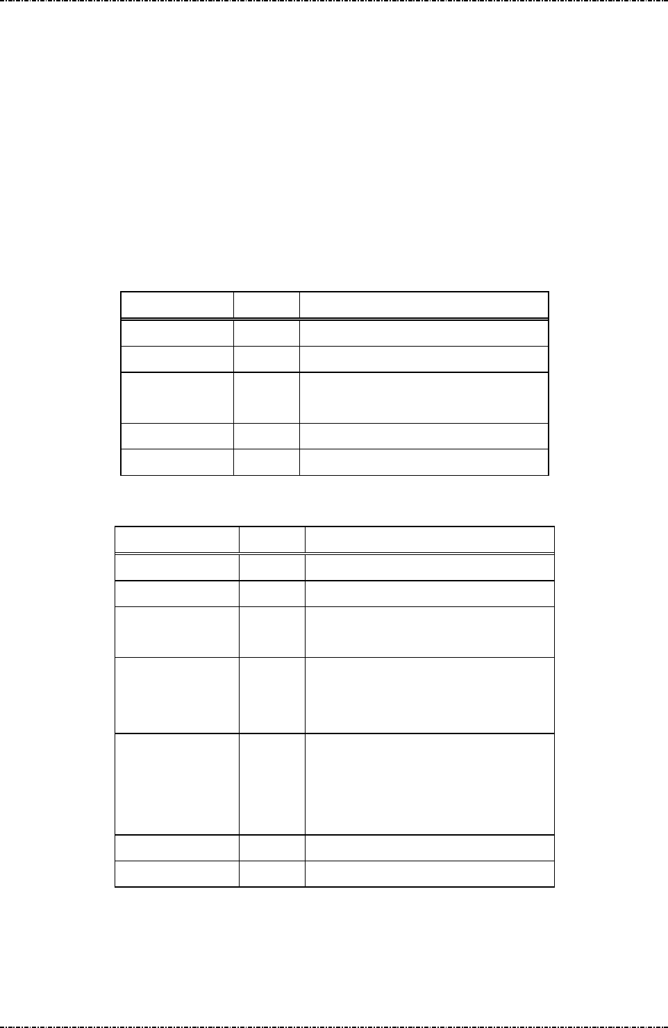
PIN Pad 791 Programmer’s Manual (PCI POS-A) UDN PM0103-U Rev. 06
Section 8 – MIFARE card messages 2015-04-20
Page174
Uniform Industrial Corp. Proprietary and Confidential Total 342 pages
Message P10 MIFARE Classic/Ultralight Card Read Block
Format: <STX>P10[Block number]<ETX>[LRC] (request frame)
<STX>P10[Result][Block data][Reason]<ETX>[LRC]
(response frame)
Message length: Fixed 9 bytes for request frame
Fixed 8 or 39 bytes for response frame.
Usage: Read the block data.
Message element:
Request frame (HOST to PIN pad)
Field Length
Value and description
<STX> 1 <02>
P10 3 Message ID
[Block number] 3 The block number.
Decimal string: 000~255.
<ETX> 1 <03>
[LRC] 1 Checksum
Response frame (PIN pad to HOST)
Field Length
Value and description
<STX> 1 <02>
P10 3 Message ID
[Result] 1 ‘0’: Success.
‘1’: Fail.
[Block data] 32. Optional: if [Result] = ‘0’
The block data.
Format: hexadecimal string.
[Reason] 1 Optional: if [Result] = ‘1’
‘1’: Format error.
‘2’: Sequence error.
‘3’: Read data fail.
<ETX> 1 <03>
[LRC] 1 Checksum

PIN Pad 791 Programmer’s Manual (PCI POS-A) UDN PM0103-U Rev. 06
Section 8 – MIFARE card messages 2015-04-20
Page175
Uniform Industrial Corp. Proprietary and Confidential Total 342 pages
Message flow:
HOST Direction
PIN pad
Message P10 (request
frame)
<ACK> (Good LRC)
<NAK> (Bad LRC)
<EOT> (after 3 NAKs)
Message P10 (response
frame)
<ACK> (Good LRC)
<NAK> (Bad LRC)
<EOT> (after 3 NAKs)

PIN Pad 791 Programmer’s Manual (PCI POS-A) UDN PM0103-U Rev. 06
Section 8 – MIFARE card messages 2015-04-20
Page176
Uniform Industrial Corp. Proprietary and Confidential Total 342 pages
Message P11 MIFARE Classic/Ultralight Card Write Block
Format: <STX>P11[Block number][Block data]<ETX>[LRC]
(request frame)
<STX>P11[Result][Reason]<ETX>[LRC] (response frame)
Message length: Fixed 41 bytes for request frame
Fixed 7 or 8 bytes for response frame.
Usage: Write the data to the specific block.
Message element:
Request frame (HOST to PIN pad)
Field Length
Value and description
<STX> 1 <02>
P11 3 Message ID
[Block number] 3 The block number.
Decimal string: 000~255.
[Block data] 32 The block data will write to MIFARE
card.
Format: hexadecimal string.
<ETX> 1 <03>
[LRC] 1 Checksum
Response frame (PIN pad to HOST)
Field Length
Value and description
<STX> 1 <02>
P11 3 Message ID
[Result] 1 ‘0’: Success.
‘1’: Fail.
[Reason] 1 Optional: if [Result] = ‘1’
‘1’: Format error.
‘2’: Sequence error.
‘3’: Write data fail.
<ETX> 1 <03>
[LRC] 1 Checksum

PIN Pad 791 Programmer’s Manual (PCI POS-A) UDN PM0103-U Rev. 06
Section 8 – MIFARE card messages 2015-04-20
Page177
Uniform Industrial Corp. Proprietary and Confidential Total 342 pages
Message flow:
HOST Direction
PIN pad
Message P11 (request
frame)
<ACK> (Good LRC)
<NAK> (Bad LRC)
<EOT> (after 3 NAKs)
Message P11 (response
frame)
<ACK> (Good LRC)
<NAK> (Bad LRC)
<EOT> (after 3 NAKs)
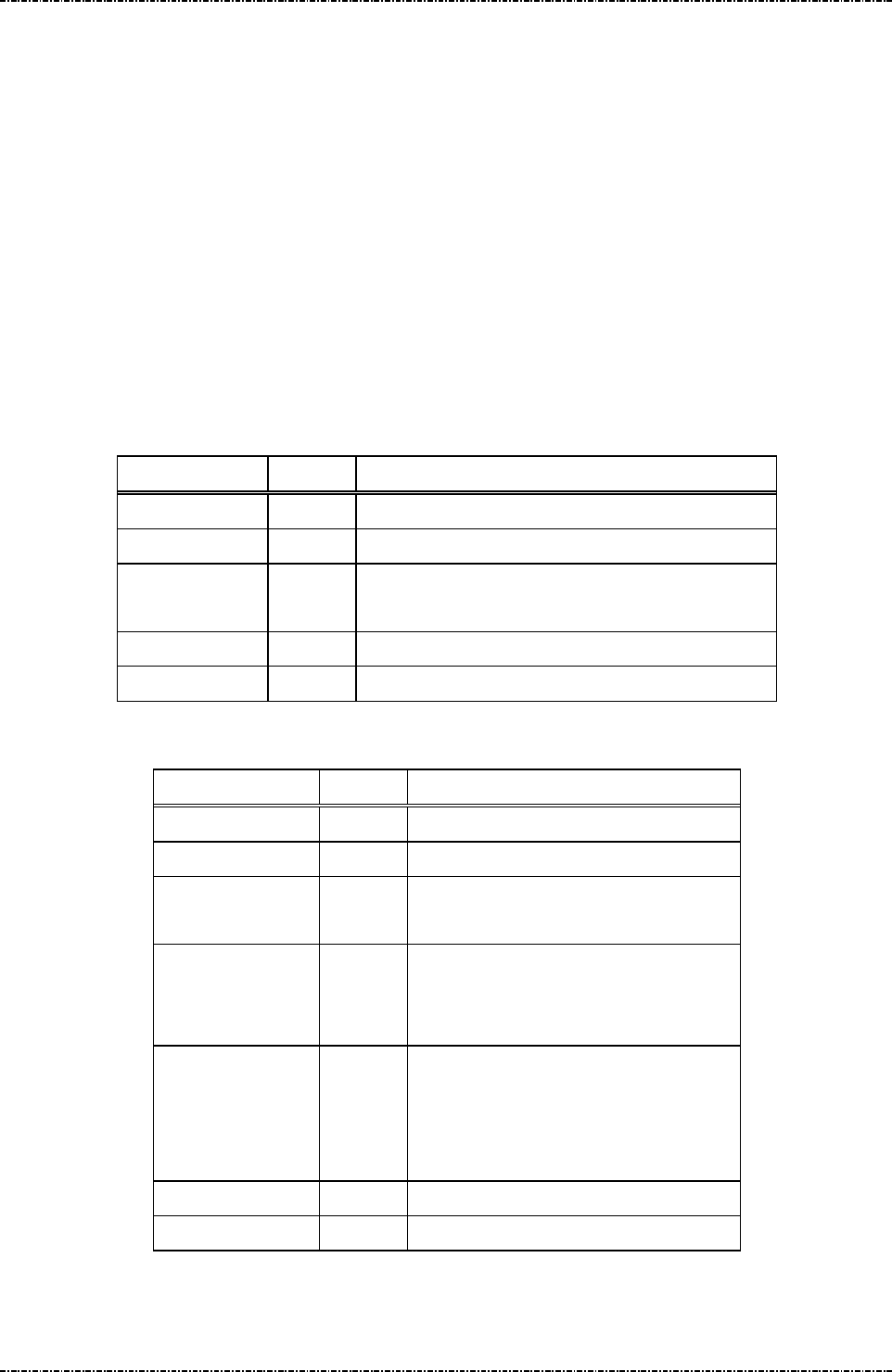
PIN Pad 791 Programmer’s Manual (PCI POS-A) UDN PM0103-U Rev. 06
Section 8 – MIFARE card messages 2015-04-20
Page178
Uniform Industrial Corp. Proprietary and Confidential Total 342 pages
Message P12 MIFARE Classic/Ultralight Card Read Sector
Format: <STX>P12[Sector number]<ETX>[LRC] (request frame)
<STX>P12[Result][Sector data][Reason]<ETX>[LRC]
(response frame)
Message length: Fixed 8 bytes for request frame
Variable for response frame.
Usage: Read a sector data from MIFARE card.
NOTE: For MIFARE Classic 4K, sector 0~31 contains 4 blocks each and sectors 32~39
contains 16 blocks each.
Message element:
Request frame (HOST to PIN pad)
Field Length
Value and description
<STX> 1 <02>
P12 3 Message ID
[Sector number] 2 The sector number.
Decimal string: 00~39.
<ETX> 1 <03>
[LRC] 1 Checksum
Response frame (PIN pad to HOST)
Field Length
Value and description
<STX> 1 <02>
P12 3 Message ID
[Result] 1 ‘0’: Success.
‘1’: Fail.
[Sector data] 128 or
512
Optional: if [Result] = ‘0’
The Sector data.
Format: hexadecimal string.
[Reason] 1 Optional: if [Result] = ‘1’
‘1’: Format error.
‘2’: Sequence error.
‘3’: Read data fail.
<ETX> 1 <03>
[LRC] 1 Checksum

PIN Pad 791 Programmer’s Manual (PCI POS-A) UDN PM0103-U Rev. 06
Section 8 – MIFARE card messages 2015-04-20
Page179
Uniform Industrial Corp. Proprietary and Confidential Total 342 pages
Message flow:
HOST Direction
PIN pad
Message P12 (request
frame)
<ACK> (Good LRC)
<NAK> (Bad LRC)
<EOT> (after 3 NAKs)
Message P12 (response
frame)
<ACK> (Good LRC)
<NAK> (Bad LRC)
<EOT> (after 3 NAKs)

PIN Pad 791 Programmer’s Manual (PCI POS-A) UDN PM0103-U Rev. 06
Section 8 – MIFARE card messages 2015-04-20
Page180
Uniform Industrial Corp. Proprietary and Confidential Total 342 pages
Message P13 MIFARE Classic/Ultralight Card Write Sector
Format: <STX>P13[Sector number][Sector data]<ETX>[LRC]
(request frame)
<STX>P13[Result][Reason]<ETX>[LRC] (response frame)
Message length: Variable for request frame
Fixed 7 or 8 bytes for response frame.
Usage: Write a sector data to MIFARE card.
NOTE: ultra light card -
sector 0: 48 bytes ( 96 bytes hexadecimal string ).
ultra light C card -
sector 1: 64 bytes. ( 128 bytes hexadecimal string ).
sector 2: 32 bytes. ( 64 bytes hexadecimal string ).
classic 1K card and classic 4K card -
sector 0: 32 bytes. ( 64 bytes hexadecimal string ).
sector 1-31: 48 bytes. ( 96 bytes hexadecimal string ).
classic 4K card -
sector 32-39: 240 bytes. ( 480 bytes hexadecimal string ).
Message element:
Request frame (HOST to PIN pad)
Field Length
Value and description
<STX> 1 <02>
P13 3 Message ID
[Sector number] 2 The sector number.
Decimal string: 00~39.
[Sector data] 64 or
96 or
128 or
480
The data will write to MIFARE card.
Format: hexadecimal string.
<ETX> 1 <03>
[LRC] 1 Checksum

PIN Pad 791 Programmer’s Manual (PCI POS-A) UDN PM0103-U Rev. 06
Section 8 – MIFARE card messages 2015-04-20
Page181
Uniform Industrial Corp. Proprietary and Confidential Total 342 pages
Response frame (PIN pad to HOST)
Field Length
Value and description
<STX> 1 <02>
P13 3 Message ID
[Result] 1 ‘0’: Success.
‘1’: Fail.
[Reason] 1 Optional: if [Result] = ‘1’
‘1’: Format error.
‘2’: Sequence error.
‘3’: Write sector fail.
<ETX> 1 <03>
[LRC] 1 Checksum
Message flow:
HOST Direction
PIN pad
Message P13 (request
frame)
<ACK> (Good LRC)
<NAK> (Bad LRC)
<EOT> (after 3 NAKs)
Message P13 (response
frame)
<ACK> (Good LRC)
<NAK> (Bad LRC)
<EOT> (after 3 NAKs)

PIN Pad 791 Programmer’s Manual (PCI POS-A) UDN PM0103-U Rev. 06
Section 8 – MIFARE card messages 2015-04-20
Page182
Uniform Industrial Corp. Proprietary and Confidential Total 342 pages
Message P14 MIFARE Classic Card Value Operation
Format: <STX>P14[Block number][Op mode][Value][Transfer block]
<ETX>[LRC] (request frame)
<STX>P14[Result][Reason]<ETX>[LRC] (response frame)
Message length: Fixed 13, 18 or 21 bytes for request frame
Fixed 7 or 8 bytes for response frame.
Usage: Value operation with block data.
Message element:
Request frame (HOST to PIN pad)
Field Length
Value and description
<STX> 1 <02>
P14 3 Message ID
[Block number] 3 The block number.
Decimal string: 000~255.
[op mode] 1 Operation mode:
'0' = Create MIFARE Value block.
'1' = Decrement.
'2' = Increment.
'3' = Copy block.
[Value] 8 (Optional), if [op mode] != '3'
Value blocks allow performing electronic purse
functions.
Format: hexadecimal string ( signed integer ).
Ex : 1234567d = 00 12 D6 87
[Transfer block] 3 (Optional), if [op mode] != '0'
The block number.
Decimal string: 000~255.
<ETX> 1 <03>
[LRC] 1 Checksum

PIN Pad 791 Programmer’s Manual (PCI POS-A) UDN PM0103-U Rev. 06
Section 8 – MIFARE card messages 2015-04-20
Page183
Uniform Industrial Corp. Proprietary and Confidential Total 342 pages
Response frame (PIN pad to HOST)
Field Length
Value and description
<STX> 1 <02>
P14 3 Message ID
[Result] 1 ‘0’: Success.
‘1’: Fail.
[Reason] 1 Optional: if [Result] = ‘1’
‘1’: Format error.
‘2’: Sequence error.
‘3’: Create value block fail.
‘4’: Value restore fail.
‘5’: Value operation fail.
‘6’: Value transfer fail.
<ETX> 1 <03>
[LRC] 1 Checksum
Message flow:
HOST Direction
PIN pad
Message P14 (request
frame)
<ACK> (Good LRC)
<NAK> (Bad LRC)
<EOT> (after 3 NAKs)
Message P14 (response
frame)
<ACK> (Good LRC)
<NAK> (Bad LRC)
<EOT> (after 3 NAKs)
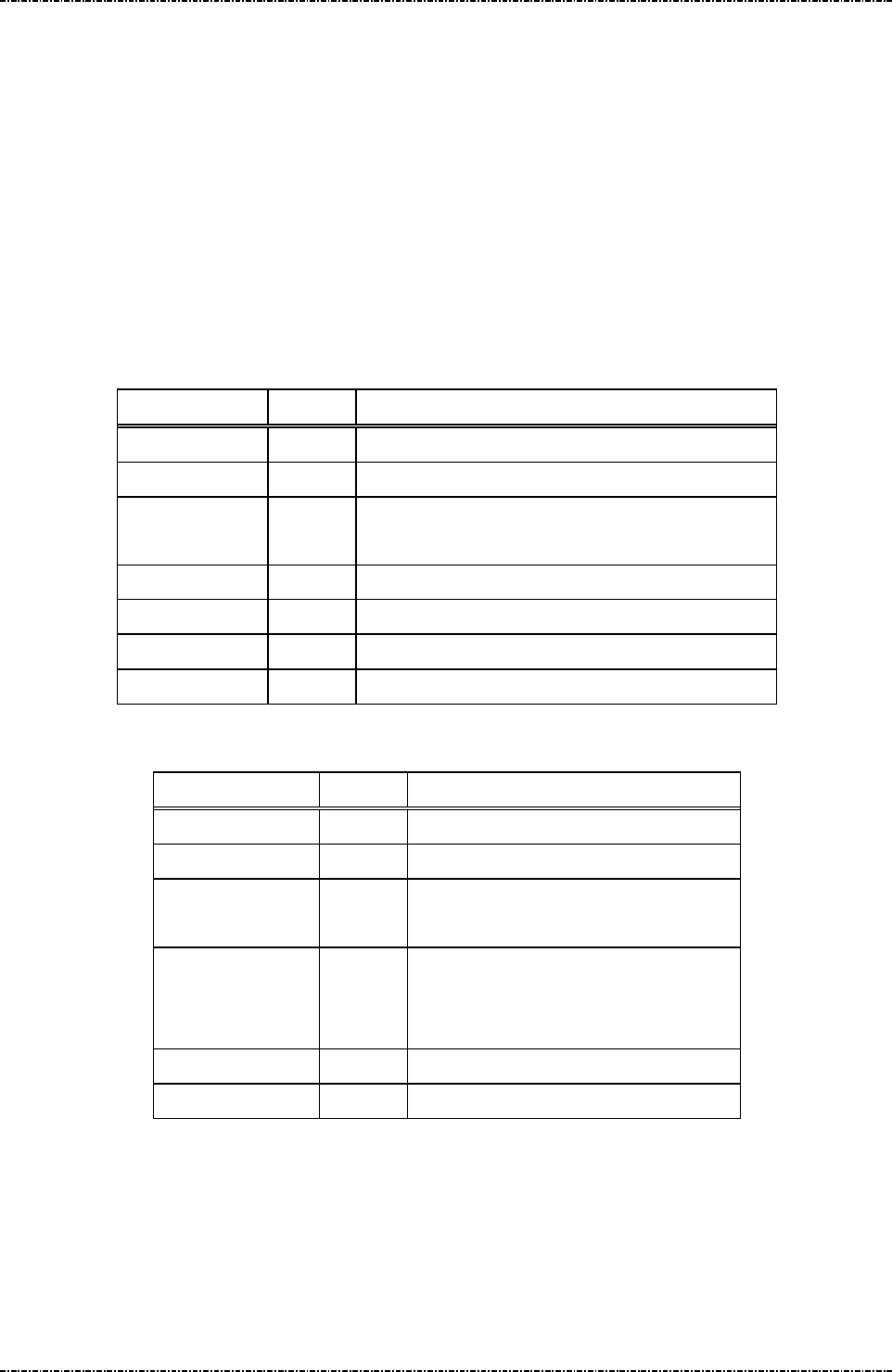
PIN Pad 791 Programmer’s Manual (PCI POS-A) UDN PM0103-U Rev. 06
Section 8 – MIFARE card messages 2015-04-20
Page184
Uniform Industrial Corp. Proprietary and Confidential Total 342 pages
Message P15 Load MIFARE key
Format: <STX>P15[Key number][Key A value][Key B value]<ETX>[LRC]
(request frame)
<STX>P15[Result][Reason]<ETX>[LRC] (response frame)
Message length: Fixed 33 bytes for request frame
Fixed 7 or 8 bytes for response frame.
Usage: PIN pad can save up to 256 key sets for MIFARE Classic card application.
Message element:
Request frame (HOST to PIN pad)
Field Length
Value and description
<STX> 1 <02>
P15 3 Message ID
[Key number] 3 The key unique number.
Range:’000’~’255’
[Key A value] 12 The key A data will store in PIN pad.
[Key B value] 12 The key B data will store in PIN pad.
<ETX> 1 <03>
[LRC] 1 Checksum
Response frame (PIN pad to HOST)
Field Length
Value and description
<STX> 1 <02>
P15 3 Message ID
[Result] 1 ‘0’: Success.
‘1’: Fail.
[Reason] 1 Optional: if [Result] = ‘1’
‘1’: Format error.
‘2’: Load MIFARE key fail.
<ETX> 1 <03>
[LRC] 1 Checksum

PIN Pad 791 Programmer’s Manual (PCI POS-A) UDN PM0103-U Rev. 06
Section 8 – MIFARE card messages 2015-04-20
Page185
Uniform Industrial Corp. Proprietary and Confidential Total 342 pages
Message flow:
HOST Direction
PIN pad
Message P15 (request
frame)
<ACK> (Good LRC)
<NAK> (Bad LRC)
<EOT> (after 3 NAKs)
Message P15 (response
frame)
<ACK> (Good LRC)
<NAK> (Bad LRC)
<EOT> (after 3 NAKs)
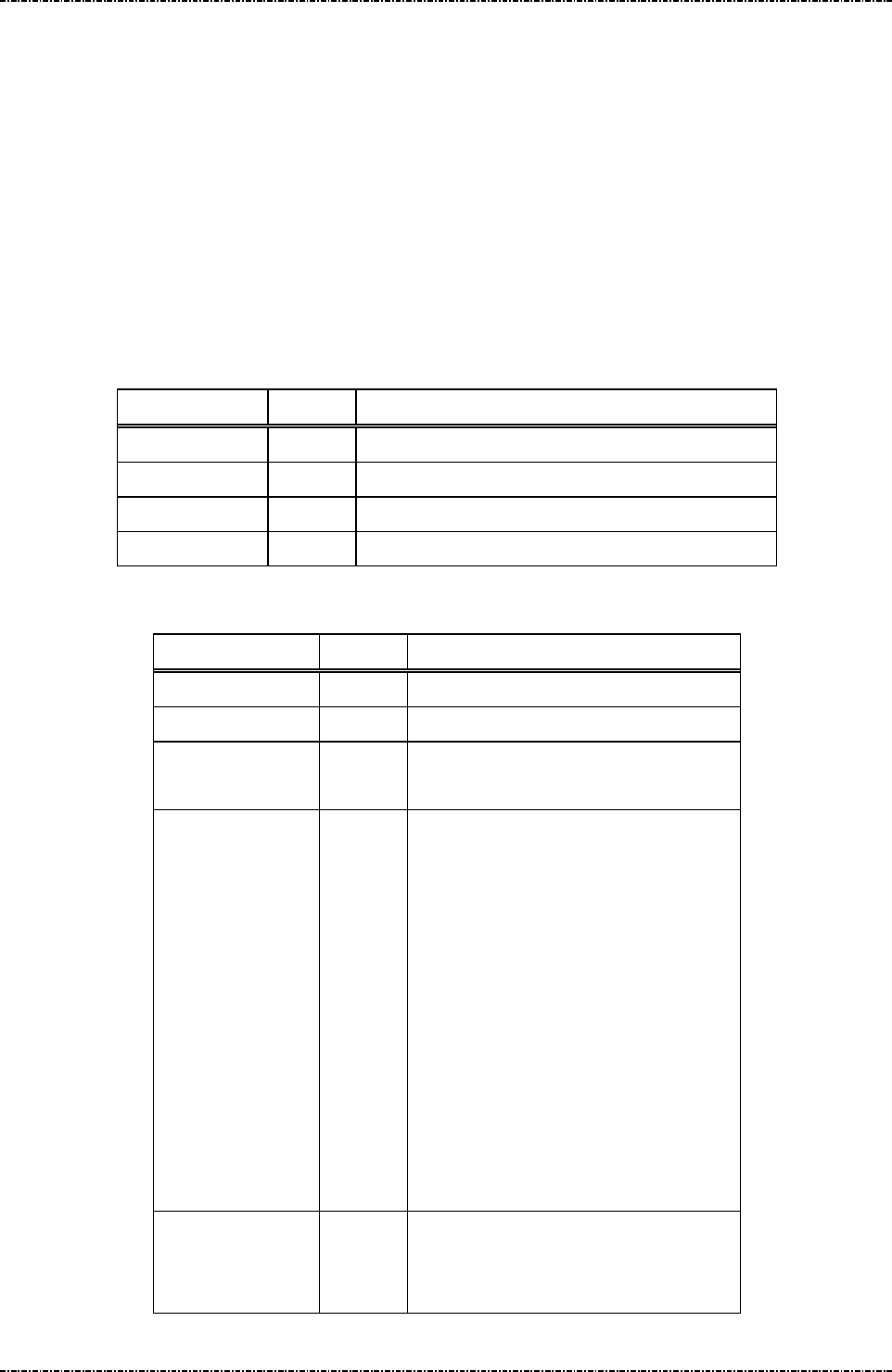
PIN Pad 791 Programmer’s Manual (PCI POS-A) UDN PM0103-U Rev. 06
Section 8 – MIFARE card messages 2015-04-20
Page186
Uniform Industrial Corp. Proprietary and Confidential Total 342 pages
Message P16 Identify MIFARE Card Type
Format: <STX>P16<ETX>[LRC] (request frame)
<STX>P16[Result][Card type][Reason]<ETX>[LRC]
(response frame)
Message length: Fixed 6 bytes for request frame
Fixed 8 bytes for response frame.
Usage: This command reports MIFARE card type.
Message element:
Request frame (HOST to PIN pad)
Field Length
Value and description
<STX> 1 <02>
P16 3 Message ID
<ETX> 1 <03>
[LRC] 1 Checksum
Response frame (PIN pad to HOST)
Field Length
Value and description
<STX> 1 <02>
P16 3 Message ID
[Result] 1 ‘0’: Success.
‘1’: Fail.
[Card type] 1 Optional: if [Result] = ‘0’
‘0’: Not MIFARE card or not supported
card.
‘1’: MIFARE Ultralight.
‘2’: MIFARE Classic 1K.
‘3’: MIFARE Classic 4K.
‘4’: MIFARE DESFire.
‘5’: MIFARE Plus
‘6’: MIFARE Mini.
‘7’: MPCOS Gemplus.
‘8’: Jewel for Innovision.
‘9’: JCOP31.
[Reason] 1 Optional: if [Result] = ‘1’
‘1’: Format error.
‘2’: Sequence error.

PIN Pad 791 Programmer’s Manual (PCI POS-A) UDN PM0103-U Rev. 06
Section 8 – MIFARE card messages 2015-04-20
Page187
Uniform Industrial Corp. Proprietary and Confidential Total 342 pages
‘3’: Card detect fail.
<ETX> 1 <03>
[LRC] 1 Checksum
Message flow:
HOST Direction
PIN pad
Message P16 (request
frame)
<ACK> (Good LRC)
<NAK> (Bad LRC)
<EOT> (after 3 NAKs)
Message P16 (response
frame)
<ACK> (Good LRC)
<NAK> (Bad LRC)
<EOT> (after 3 NAKs)

PIN Pad 791 Programmer’s Manual (PCI POS-A) UDN PM0103-U Rev. 06
Section 8 – MIFARE card messages 2015-04-20
Page188
Uniform Industrial Corp. Proprietary and Confidential Total 342 pages
Message P17 MIFARE DESfire Card Activation
Format: <STX>P17<ETX>[LRC] (request frame)
<STX>P17[Result][ATS/PUPI][Reason]<ETX>[LRC] (response frame)
Message length: Fixed 6 bytes for request frame
Variable for response frame.
Usage: This command will activate PICC card.
Message element:
Request frame (HOST to PIN pad)
Field Length
Value and description
<STX> 1 <02>
P17 3 Message ID
<ETX> 1 <03>
[LRC] 1 Checksum
Response frame (PIN pad to HOST)
Field Length
Value and description
<STX> 1 <02>
P17 3 Message ID
[Result] 1 ‘0’: Success.
‘1’: Fail.
[ATS/PUPI] Var. Optional: if [Result] = ‘0’
[Reason] 1 Optional: if [Result] = ‘1’
‘1’: Format error.
‘2’: Sequence error.
‘3’: Card activate fail.
<ETX> 1 <03>
[LRC] 1 Checksum

PIN Pad 791 Programmer’s Manual (PCI POS-A) UDN PM0103-U Rev. 06
Section 8 – MIFARE card messages 2015-04-20
Page189
Uniform Industrial Corp. Proprietary and Confidential Total 342 pages
Message flow:
HOST Direction
PIN pad
Message P17 (request
frame)
<ACK> (Good LRC)
<NAK> (Bad LRC)
<EOT> (after 3 NAKs)
Message P17 (response
frame)
<ACK> (Good LRC)
<NAK> (Bad LRC)
<EOT> (after 3 NAKs)
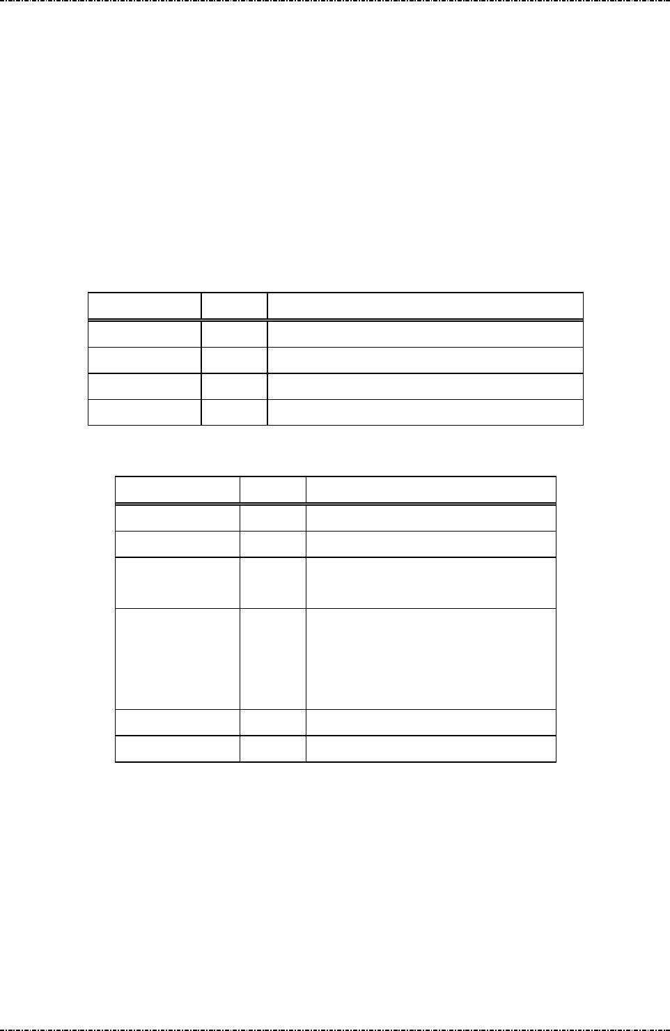
PIN Pad 791 Programmer’s Manual (PCI POS-A) UDN PM0103-U Rev. 06
Section 8 – MIFARE card messages 2015-04-20
Page190
Uniform Industrial Corp. Proprietary and Confidential Total 342 pages
Message P18 MIFARE DESfire Card Deselect
Format: <STX>P18<ETX>[LRC] (request frame)
<STX>P18[Result][Reason]<ETX>[LRC] (response frame)
Message length: Fixed 6 bytes for request frame
Fixed 7 or 8 bytes for response frame.
Usage: Sends ISO/IEC 14443-4 DESELECT command to the card. After the card receive
DESELECT command, the card will be brought to the HALT state.
Message element:
Request frame (HOST to PIN pad)
Field Length
Value and description
<STX> 1 <02>
P18 3 Message ID
<ETX> 1 <03>
[LRC] 1 Checksum
Response frame (PIN pad to HOST)
Field Length
Value and description
<STX> 1 <02>
P18 3 Message ID
[Result] 1 ‘0’: Success.
‘1’: Fail.
[Reason] 1 Optional: if [Result] = ‘1’
‘1’: Format error.
‘2’: Sequence error.
‘3’: DESELECT execute fail.
<ETX> 1 <03>
[LRC] 1 Checksum

PIN Pad 791 Programmer’s Manual (PCI POS-A) UDN PM0103-U Rev. 06
Section 8 – MIFARE card messages 2015-04-20
Page191
Uniform Industrial Corp. Proprietary and Confidential Total 342 pages
Message flow:
HOST Direction
PIN pad
Message P18 (request
frame)
<ACK> (Good LRC)
<NAK> (Bad LRC)
<EOT> (after 3 NAKs)
Message P18 (response
frame)
<ACK> (Good LRC)
<NAK> (Bad LRC)
<EOT> (after 3 NAKs)
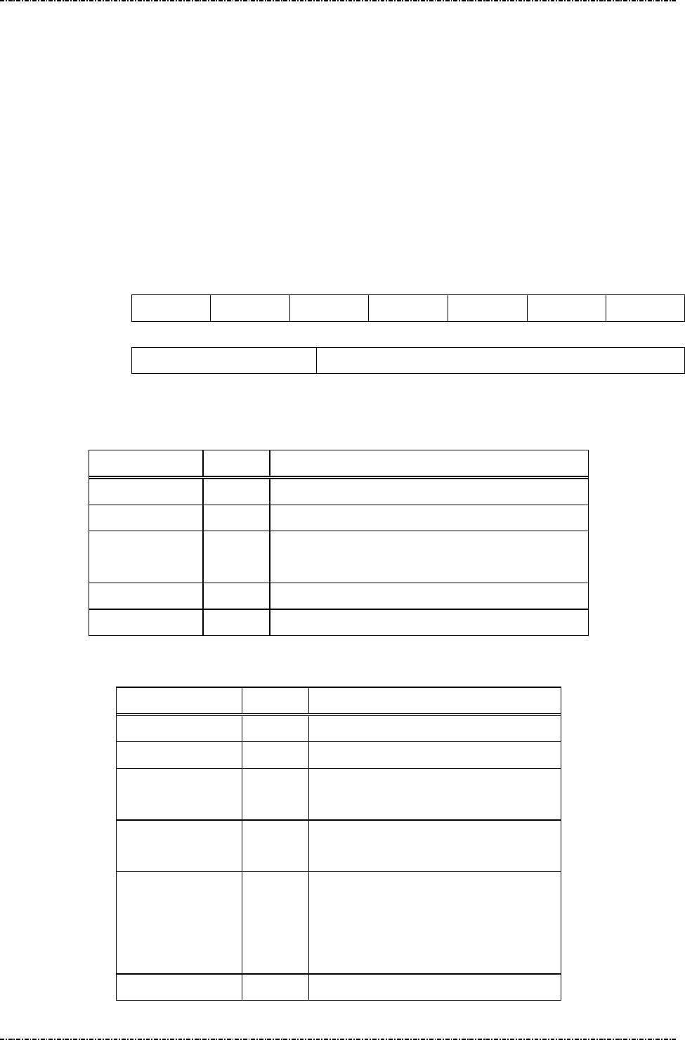
PIN Pad 791 Programmer’s Manual (PCI POS-A) UDN PM0103-U Rev. 06
Section 8 – MIFARE card messages 2015-04-20
Page192
Uniform Industrial Corp. Proprietary and Confidential Total 342 pages
Message P19 I/O to MIFARE card with APDU format
Format: <STX>P19[C-APDU]<ETX>[LRC] (request frame)
<STX>P19[Result][R-APDU][Reason]<ETX>[LRC]
(response frame)
Message length: variable.
Usage: The command is used to pass an APDU to the card where both data and an ISO status
are expected in the response.
Note: 1. The APDU(Application Protocol Data Unit) format defined in ISO/IEC 7816-4
chapter 5. Below brief the command and response APDU.
C-APDU format
CLA INS P1 P2 Lc Data Le
R-APDU format
Data(Optional) SW1-SW2
Message element:
Request frame (HOST to PIN pad)
Field Length
Value and description
<STX> 1 <02>
P19 3 Message ID
[C-APDU] Var. Command APDU. The C-APDU format please see
Note 1.
<ETX> 1 <03>
[LRC] 1 Checksum
Response frame (PIN pad to HOST)
Field Length
Value and description
<STX> 1 <02>
P19 3 Message ID
[Result] 1 ‘0’: Success.
‘1’: Fail.
[R-APDU] Var. Optional: if [Result] = ‘0’
The R-APDU format please see Note 1.
[Reason] 1 Optional: if [Result] = ‘1’
‘1’: Format error.
‘2’: Sequence error.
‘3’: APDU fail.
<ETX> 1 <03>

PIN Pad 791 Programmer’s Manual (PCI POS-A) UDN PM0103-U Rev. 06
Section 8 – MIFARE card messages 2015-04-20
Page193
Uniform Industrial Corp. Proprietary and Confidential Total 342 pages
[LRC] 1 Checksum
Message flow:
HOST Direction
PIN pad
Message P19 (request
frame)
<ACK> (Good LRC)
<NAK> (Bad LRC)
<EOT> (after 3 NAKs)
Message P19 (response
frame)
<ACK> (Good LRC)
<NAK> (Bad LRC)
<EOT> (after 3 NAKs)
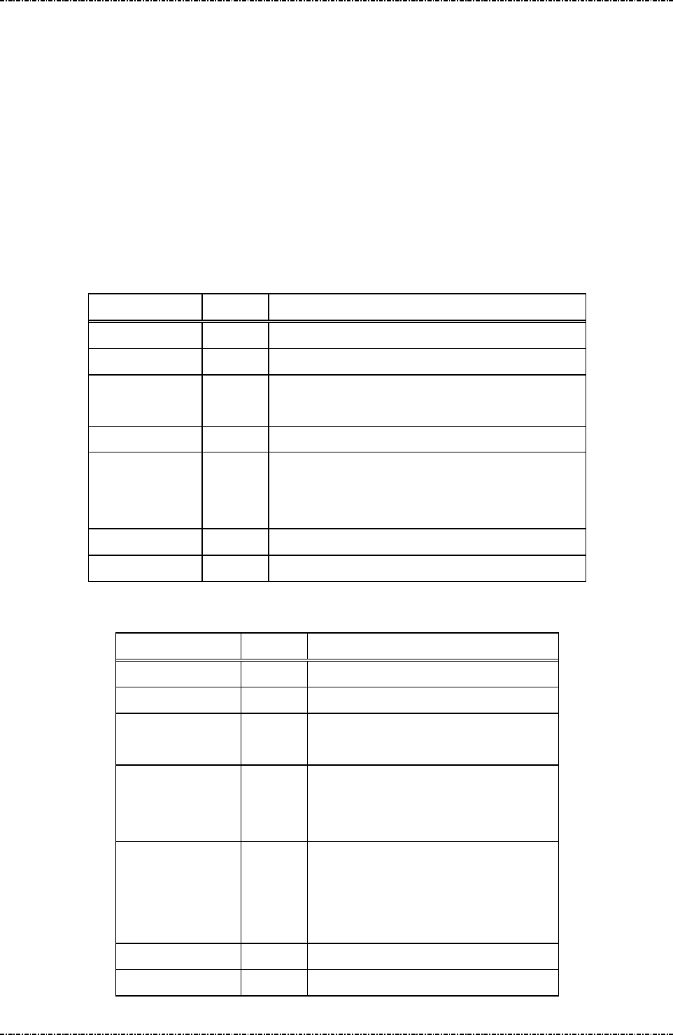
PIN Pad 791 Programmer’s Manual (PCI POS-A) UDN PM0103-U Rev. 06
Section 8 – MIFARE card messages 2015-04-20
Page194
Uniform Industrial Corp. Proprietary and Confidential Total 342 pages
Message P20 I/O to MIFARE card for block data exchange
Format: <STX>P20[CRC mode][Wait time][Block data]<ETX>[LRC]
(request frame)
<STX>P20[Result][Block data][Reason]<ETX>[LRC]
(response frame)
Message length: variable.
Usage: The command is used to pass a block data to a card.
Note: 1. The format of block data defined in ISO/IEC 14443-4 chapter 7.
Message element:
Request frame (HOST to PIN pad)
Field Length
Value and description
<STX> 1 <02>
P20 3 Message ID
[CRC mode] 1 ‘0’ : No CRC in [block data].
‘1’ : [Block data] contain CRC.
[Wait time] 4 The time out value for card response.
[Block data] Var. Format: hexadecimal string.
The command use block format as defined in ISO
14443-4.
<ETX> 1 <03>
[LRC] 1 Checksum
Response frame (PIN pad to HOST)
Field Length
Value and description
<STX> 1 <02>
P20 3 Message ID
[Result] 1 ‘0’: Success.
‘1’: Fail.
[Block data] Var. Optional: if [Result] = ‘0’
The card response data with block
format as defined in ISO 14443-4.
[Reason] 1 Optional: if [Result] = ‘1’
‘1’: Format error.
‘2’: Sequence error.
‘3’: Data exchange fail.
<ETX> 1 <03>
[LRC] 1 Checksum

PIN Pad 791 Programmer’s Manual (PCI POS-A) UDN PM0103-U Rev. 06
Section 8 – MIFARE card messages 2015-04-20
Page195
Uniform Industrial Corp. Proprietary and Confidential Total 342 pages
Message flow:
HOST Direction
PIN pad
Message P20(request
frame)
<ACK> (Good LRC)
<NAK> (Bad LRC)
<EOT> (after 3 NAKs)
Message P20 (response
frame)
<ACK> (Good LRC)
<NAK> (Bad LRC)
<EOT> (after 3 NAKs)

PIN Pad 791 Programmer’s Manual (PCI POS-A) UDN PM0103-U Rev. 06
Section 8 – MIFARE card messages 2015-04-20
Page196
Uniform Industrial Corp. Proprietary and Confidential Total 342 pages
Overall MIFARE operation flow reference
Before any memory operation for MIFARE card, user need to activate the card as follows.
Ref. 1 Activate and authenticate for MIFARE classic card.
HOST Direction PIN pad
P01 (Enable Mifare)
P01 (Response Frame)
P02 (Query MIFARE Presence)
P02 (Response Frame)
P03 (Anti-collision)
P03 (Response Frame)
P04 (Selection)
P04 (Response Frame)
P16 (Identify MIFARE Card Type)
P16 (Response Frame)
‘2’: MIFARE Classic 1K.
‘3’: MIFARE Classic 4K.
P07 (Classic Card Authentication)
P07 (Response Frame)
Now, user can access memory
operation for MIFRE card(like P10,
P11, P12, P13, P14)
The response of memory operation
command.
P06 (Card HALT)
P06 (Response Frame)
P01 (Disable Mifare)
P01 (Response Frame)

PIN Pad 791 Programmer’s Manual (PCI POS-A) UDN PM0103-U Rev. 06
Section 8 – MIFARE card messages 2015-04-20
Page197
Uniform Industrial Corp. Proprietary and Confidential Total 342 pages
Ref. 2 The quick method for activating classic card.
HOST Direction PIN pad
P01 (Enable Mifare)
P01 (Response Frame)
P05 (Classic Card Activation)
P05 (Response Frame)
P16 (Identify MIFARE Card Type)
P16 (Response Frame)
‘2’: MIFARE Classic 1K.
‘3’: MIFARE Classic 4K.
P07 (Classic Card Authentication)
P07 (Response Frame)
Now, user can access memory
operation for MIFRE card(like P10,
P11, P12, P13, P14)
The response of memory operation
command.
P06 (Card HALT)
P06 (Response Frame)
P01 (Disable Mifare)
P01 (Response Frame)

PIN Pad 791 Programmer’s Manual (PCI POS-A) UDN PM0103-U Rev. 06
Section 8 – MIFARE card messages 2015-04-20
Page198
Uniform Industrial Corp. Proprietary and Confidential Total 342 pages
Ref. 3 Activate and authenticate for MIFARE Ultralight card.
HOST Direction PIN pad
P01 (Enable Mifare)
P01 (Response Frame)
P02 (Query MIFARE Presence)
P02 (Response Frame)
P03 (Anti-collision)
P03 (Response Frame)
P04 (Selection)
P04 (Response Frame)
P16 (Identify MIFARE Card Type)
P16 (Response Frame)
‘1’: MIFARE Ultralight.
Now, user can access memory
operation for MIFRE card(like P08,
P09, P10, P11, P12, P13)
The response of memory operation
command.
P06 (Card HALT)
P06 (Response Frame)
P01 (Disable Mifare)
P01 (Response Frame)

PIN Pad 791 Programmer’s Manual (PCI POS-A) UDN PM0103-U Rev. 06
Section 8 – MIFARE card messages 2015-04-20
Page199
Uniform Industrial Corp. Proprietary and Confidential Total 342 pages
Ref. 4 The quick method for activating Ultralight card.
HOST Direction PIN pad
P01 (Enable Mifare)
P01 (Response Frame)
P05 (Ultralight Card Activation)
P05 (Response Frame)
P16 (Identify MIFARE Card Type)
P16 (Response Frame)
‘1’: MIFARE Ultralight.
Now, user can access memory
operation for MIFRE card(like P08,
P09, P10, P11, P12, P13)
The response of memory operation
command.
P06 (Card HALT)
P06 (Response Frame)
P01 (Disable Mifare)
P01 (Response Frame)

PIN Pad 791 Programmer’s Manual (PCI POS-A) UDN PM0103-U Rev. 06
Section 8 – MIFARE card messages 2015-04-20
Page200
Uniform Industrial Corp. Proprietary and Confidential Total 342 pages
Ref. 5 Activating for DESFire card
HOST Direction PIN pad
P01 (Enable Mifare)
P01 (Response Frame)
P17 (DESfire Card Activation)
P17 (Response Frame)
P16 (Identify MIFARE Card Type)
P16 (Response Frame)
‘4’: MIFARE DESFire.
P19、P20 (Request frame)
P19、P20 (Response Frame)
P18 (DESfire Card Deselect)
P18 (Response Frame)
P01 (Disable Mifare)
P01 (Response Frame)

PIN Pad 791 Programmer’s Manual (PCI POS-A) UDN PM0103-U Rev. 06
Section 9 – Online transaction messages with Master / Session keys 2015-04-20
Page201
Uniform Industrial Corp. Proprietary and Confidential Total 342 pages
Section 9 Online transaction messages with Master/Session
Keys (MK/SK)
Message 70 PIN entry request (MK/SK)
Format: <STX>70.[Account]<FS>[session key][Amount]
<FS>[timeout]<ETX>[LRC]
Message length: Variable 36 to 51 bytes (max. 67 bytes for TDES session key).
Usage: Display prompt and accept customer PIN input. The following prompt will be displayed:
"Total Amount"
"$xxx.xx"
"Enter PIN"
"Push "ENTER""
The PIN pad will then wait till the PIN entered and [ENTER] key is pressed. After
ENTER key is pressed, the string “PIN PAD” and “PROCESSING” will be displayed
until the CLEAR key is pressed. During this period, the PIN pad will not process any
message other than the CANCEL message (message 72).
NOTE: Aborting transaction: Press CLEAR button to reset the PIN input and CAN (cancel)
button to abort the transaction.
PIN length: According to ANSI X9.8 standard, the length of PIN should between 4 to
12 digits. If user inputs less than 4 digits and press ENTER, PP791 will beep for error
and continue to wait for user’s input. When user inputs 13th character, PIN pad will
beep for error, conserves PIN character 1st to 12th, and wait for ENTER.
This message has DES Time Throttle: See Appendix A for details.
Master key must be selected before transaction: PP791 will warn and refuse
message 70 if message 08 was not issued before.
Triple DES capability: Following table shows the logic of PP791 when processing
single-length and double-length MK/SK. (TDES in EDE order, see Appendix A).
Session Key: If the selected key is with usage “P0”, the session key should be all
zeros.
Session key
Master key
Double length Single length
Double length
PP791 TDES decrypts L-key and
R-key of [session key] value, using
active master key.
PIN blocks are TDES encrypted by
decrypted session key.
PP791 TDES decrypts [session key]
value, using active master key.
PIN blocks are DES encrypted by
decrypted session key.

PIN Pad 791 Programmer’s Manual (PCI POS-A) UDN PM0103-U Rev. 06
Section 9 – Online transaction messages with Master / Session keys 2015-04-20
Page202
Uniform Industrial Corp. Proprietary and Confidential Total 342 pages
Single length
PP791 DES decrypts L-key and
R-key of [session key] value, using
active master key.
PIN blocks are TDES encrypted by
session key.
PP791 DES decrypts [session key]
value, using active master key.
PIN blocks are DES encrypted by
session key.
Message element:
Field Length
Value and description
<STX> 1 <02>
70 2 Message ID
. 1 <2E>, delimiter
[Account] 8..19 Card account number
<FS> 1 <1C>, field separator
[session key] 16 or
32
Working key encrypted using selected master
key. 32-characters session key produces TDES
encrypted PIN block with EDE order.
Format: hexadecimal string.
This filed should be all zeros if the selected key
is with usage “P0”
[Amount] 4..8 Amount of goods to be displayed on PIN pad.
<FS> 1 (optional) <1C>, field separator
[timeout] 1 (optional) ASCII character from ‘1’ to ‘9’ which
is the timeout value in the unit of 30 seconds.
Default = 9x30 = 270 seconds.
<ETX> 1 <03>
[LRC] 1 Checksum

PIN Pad 791 Programmer’s Manual (PCI POS-A) UDN PM0103-U Rev. 06
Section 9 – Online transaction messages with Master / Session keys 2015-04-20
Page203
Uniform Industrial Corp. Proprietary and Confidential Total 342 pages
Message flow:
HOST Direction PIN pad
Message 70
<ACK> (Good LRC)
<NAK> (Bad LRC)
<EOT> (after 3 NAKs)
Prompt user to enter PIN.
Message 71 or <EOT> when input
timed out or user pressed [CAN]
<ACK> (Good echo)
<NAK> (Bad LRC)
<EOT> (after 3 NAKs)
Display “PIN PAD PROCESSING”
until CLEAR pressed or another
message received.
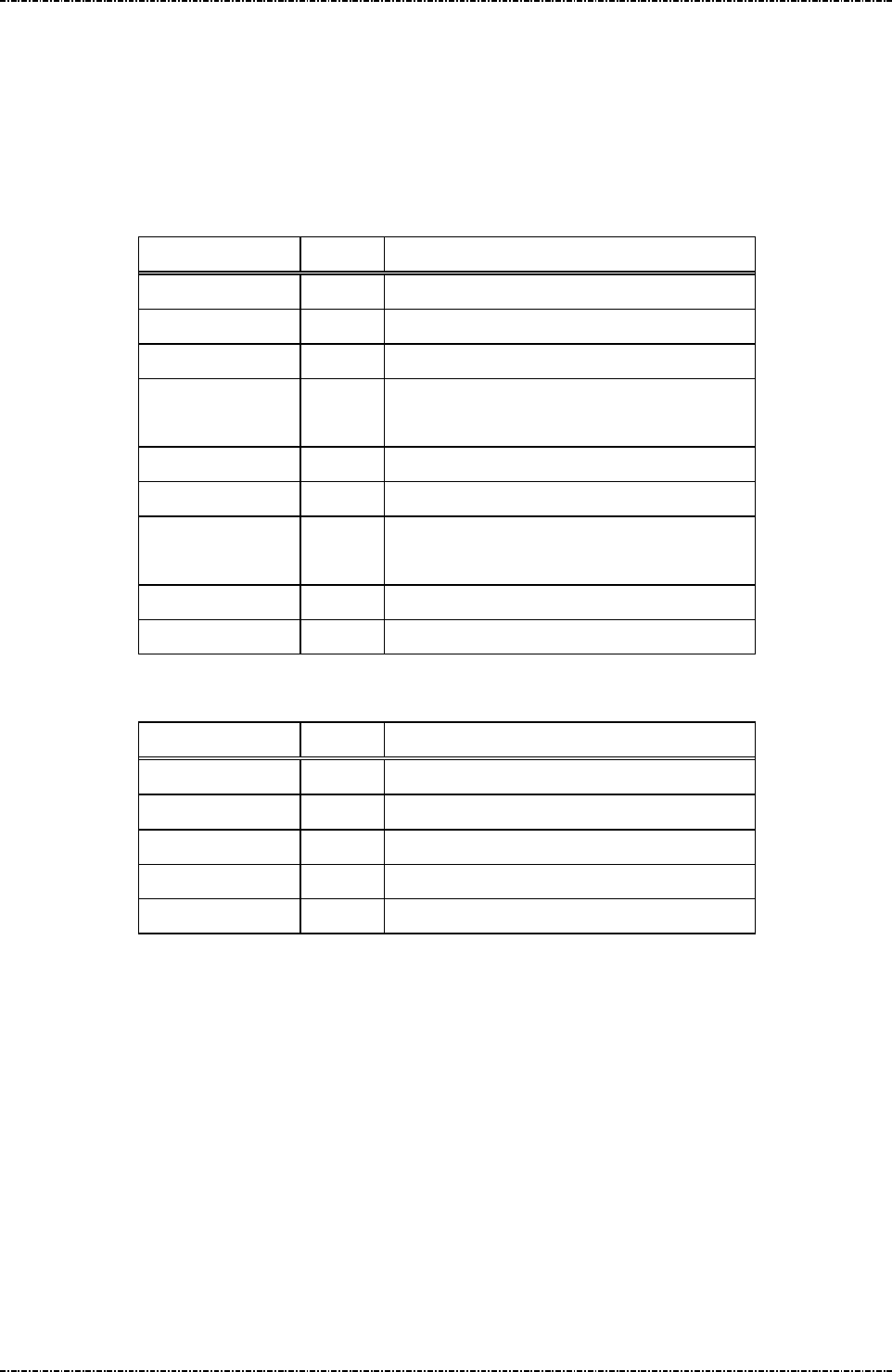
PIN Pad 791 Programmer’s Manual (PCI POS-A) UDN PM0103-U Rev. 06
Section 9 – Online transaction messages with Master / Session keys 2015-04-20
Page204
Uniform Industrial Corp. Proprietary and Confidential Total 342 pages
Message 71 Encrypted PIN Block Response
Format: <STX>71.<fkey flag><PIN length>01[PIN][LRC] (PIN block frame)
<STX>71[error code]<ETX>[LRC] (Error code frame)
Message length: Fixed 27 bytes for PIN block frame, 6 bytes for error code frame.
Usage: Send the entered PIN to HOST in encrypted format.
Message element:
Field Length
Value and description
<STX> 1 <02>
71 2 Message ID
. 1 <2E> delimiter
[Fkey flag] 1 Always ‘0’ (This field is kept to retain old
model compatibility.)
[PIN length] 2 00, 04..12 length of PIN entered
01 2 01 format of PIN block, always 01
[PIN] 16 Encrypted PIN blocks
Format: hexadecimal string.
<ETX> 1 <03>
[LRC] 1 Checksum
Message 71 (Error message)
Field Length
Value and description
<STX> 1 <02>
71 2 Message ID
[Error code] 1 Code to indicate error (see next page)
<ETX> 1 <03>
[LRC] 1 Checksum

PIN Pad 791 Programmer’s Manual (PCI POS-A) UDN PM0103-U Rev. 06
Section 9 – Online transaction messages with Master / Session keys 2015-04-20
Page205
Uniform Industrial Corp. Proprietary and Confidential Total 342 pages
Message flow:
HOST Direction PIN pad
Message 70/Z60/Z62
<ACK> (Good LRC)
<NAK> (Bad LRC)
<EOT> (after 3 NAKs)
Message 71 or <EOT> when
input tined out or user pressed
[CAN]
<ACK> (Good echo)
<NAK> (Bad LRC)
<EOT> (after 3 NAKs)
Display processing prompt
Error codes:
Code Meaning
'0' Null Account input field.
'1' Key value error.
(session key value conflicted with the usage of active master key, or
session key length longer than active master key)
'2' Account number shorter than 8 digits.
'3' Account number longer than 19 digits.
'4' Account number have character other than '0'-'9'.
'5' Working key format error.
'6' Timeout value error
'7' No more DES operation within 60 min. (see Appendix A)
'8' From 70, Amount string format error.
From Z62, PIN count, Accept Null PIN flag, and Prompt string
format error.
'9' Active master key not exist.
'A' Currently selected master key over range (Master key slot A to F
will cause this error message because they are supposed to do
authentication and MAC, not for PIN entry)
'B' Flash memory read/write error
'C' Memory buffer allocation error
'E' Data length error in a field.
'G' Specified file not found or authentication error.

PIN Pad 791 Programmer’s Manual (PCI POS-A) UDN PM0103-U Rev. 06
Section 9 – Online transaction messages with Master / Session keys 2015-04-20
Page206
Uniform Industrial Corp. Proprietary and Confidential Total 342 pages
Message 72 PIN Entry Cancel
Format: <STX>72<ETX>[LRC]
Message length: Fixed 5 bytes.
Usage: Cancel current transaction and return the PIN pad to IDLE state, used to interrupt
command in process. If PIN pad receives message 72 while processing user input
such as swipe card, enter PIN or key-in data, It will respond with <EOT> to
acknowledge that operation is canceled.
Message element:
Field Length Value and description
<STX> 1 <02>
72 2 Message ID
<ETX> 1 <03>
[LRC] 1 Checksum
Message flow:
In Idle mode (normal condition)
HOST Direction PIN Pad
Message 72
<ACK> (Good LRC)
<NAK> (Bad LRC)
<EOT> (after 3 NAKs)
In PIN/data entry mode (cancel/abort the session)
HOST Direction PIN Pad
Message 72
<EOT>
If PIN pad is in PIN/Data
entry mode or waiting for
tapping/swiping card.
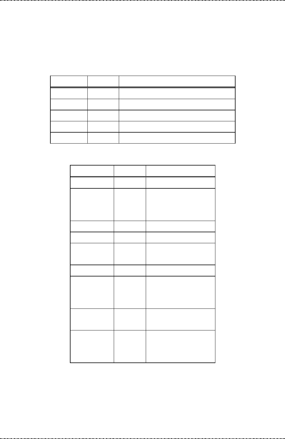
PIN Pad 791 Programmer’s Manual (PCI POS-A) UDN PM0103-U Rev. 06
Section 9 – Online transaction messages with Master / Session keys 2015-04-20
Page207
Uniform Industrial Corp. Proprietary and Confidential Total 342 pages
Message Z0 Move Display Cursor
Format: <STX>Z0[YY]<ETX>[LRC]
Message length: Fixed 7 bytes.
Usage: Move the display cursor. Z0 message is enabled when PIN pad receives first Z2
message. Under Z2-authenticated mode, Z0 message is also disabled.
Message element:
Field Length Value and description
<STX> 1 <02>
Z0 2 Message ID
[YY] 2 Y-coordinate, 01 ~ Max. line
<ETX> 1 <03>
[LRC] 1 Checksum
Message flow:
HOST Direction PIN pad
Message Z2
<ACK> (Good LRC)
<NAK> (Bad LRC)
<EOT> (after 3 NAKs)
Display string.
Message Z0
<ACK> / <NAK> /
<EOT>
PIN pad moves cursor
Message Z2
(without clear
screen)
<ACK> / <NAK> /
<EOT>
Display 2nd string from
the coordinate specified
by Z0.

PIN Pad 791 Programmer’s Manual (PCI POS-A) UDN PM0103-U Rev. 06
Section 9 – Online transaction messages with Master / Session keys 2015-04-20
Page208
Uniform Industrial Corp. Proprietary and Confidential Total 342 pages
Message Z1 Reset State
Format: <STX>Z1<ETX>[LRC]
Message length: Fixed 5 bytes.
Usage: Force the PIN pad to enter IDLE state.
This command also reset magnet card swiping command Q1, Q8, Q9 and QF.
Message element:
Field Length Value and description
<STX> 1 <02>
Z1 2 Message ID
<ETX> 1 <03>
[LRC] 1 Checksum
Message flow:
HOST Direction PIN pad
Message Z1
<ACK> (Good LRC)
<NAK> (Bad LRC)
<EOT> (after 3 NAKs)
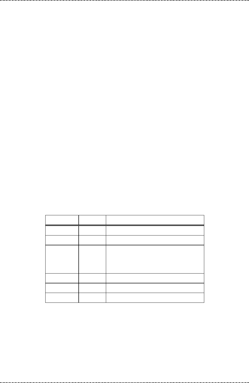
PIN Pad 791 Programmer’s Manual (PCI POS-A) UDN PM0103-U Rev. 06
Section 9 – Online transaction messages with Master / Session keys 2015-04-20
Page209
Uniform Industrial Corp. Proprietary and Confidential Total 342 pages
Message Z2 Display String
Format: <STX>Z2<SUB>[string]<ETX>[LRC] (Request frame, normal)
<STX>Z2<GS>[PromptID]<SUB><ETX>[LRC]
(Request frame, authenticated)
<STX>Z2<RS>[PromptID]<SUB><ETX>[LRC]
(Request frame, authenticated for PIN entry)
<STX>Z2[status]<ETX>[LRC]
(Response frame, authenticated)
Message length: Variable, at least 6 bytes.
Usage: PIN pad to show the indicated prompt string on its display, until [CAN] key is pressed.
If the first character of message is <GS> (0x1D) or <RS> (0x1E), PIN pad will treat
following message string as ID number, and search its predefined message table for
corresponding message string, then display the string on the screen.
Note: 1. Two Z2 message with authenticated prompt ID can be issued in serial to form a
longer sentence, or used in combination with normal string which contains only digits.
2. Z2 message with PIN entry prompt will force user issue every message with <SUB>,
which implies the PIN entry message can’t be concatenated.
3. PIN pad will temporarily turn off timer display for the first Z2 message it received.
After Z42, Z50, Z60 are performed, [CAN] key is pressed, or any other message
received and processed, PIN pad will turn on the timer display.
Message element:
Z2 request frame (normal mode)
Field Length Value and description
<STX> 1 <02>
Z2 2 Message ID
<SUB> 1 <1A> (optional)
When <SUB> exists, PIN pad will clear
screen contents.
[string] 1 .. 64 ASCII string to be displayed
<ETX> 1 <03>
[LRC] 1 Checksum
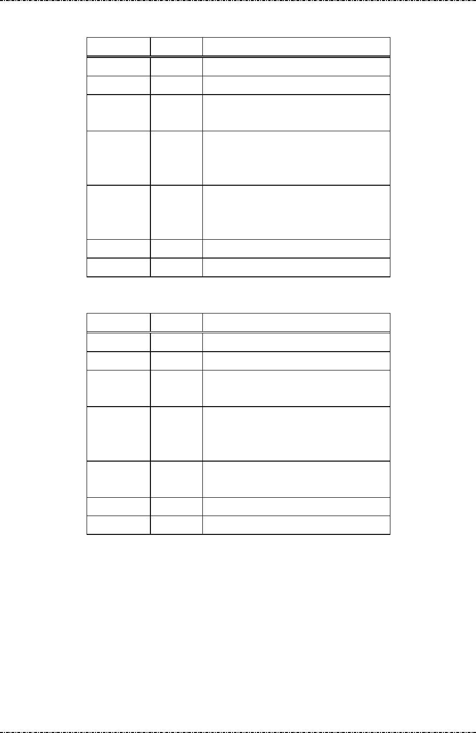
PIN Pad 791 Programmer’s Manual (PCI POS-A) UDN PM0103-U Rev. 06
Section 9 – Online transaction messages with Master / Session keys 2015-04-20
Page210
Uniform Industrial Corp. Proprietary and Confidential Total 342 pages
Z2 request frame (authenticated mode with fixed prompt)
Field Length Value and description
<STX> 1 <02>
Z2 2 Message ID
<GS> 1 <1D>, mark of authenticated frame with
fixed prompt.
Prompt ID 3 Prompt ID that corresponds to fixed
prompt provided by PIN pad.
Decimal string: 001 ~ 999.
<SUB> 1 <1A> (optional)
When <SUB> exists, PIN pad will clear
screen contents.
<ETX> 1 <03>
[LRC] 1 Checksum
Z2 request frame (PIN entry mode with fixed prompt)
Field Length Value and description
<STX> 1 <02>
Z2 2 Message ID
<RS> 1 <1E>, mark of PIN entry frame with fixed
prompt.
Prompt ID 3 Prompt ID that corresponds to fixed PIN
entry prompt provided by PIN pad.
Decimal string: 001 ~ 999.
<SUB> 1 <1A>
PIN pad will clear clear screen contents.
<ETX> 1 <03>
[LRC] 1 Checksum

PIN Pad 791 Programmer’s Manual (PCI POS-A) UDN PM0103-U Rev. 06
Section 9 – Online transaction messages with Master / Session keys 2015-04-20
Page211
Uniform Industrial Corp. Proprietary and Confidential Total 342 pages
Z2 response frame (authenticated mode)
Field Length Value and description
<STX> 1 <02>
Z2 2 Message ID
[status] 1 ‘0’: OK
‘1’: Prompt ID not supported.
<ETX> 1 <03>
[LRC] 1 Checksum
Message flow:
Normal frame
HOST Direction PIN pad
Message Z2
<ACK> (Good LRC)
<NAK> (Bad LRC)
<EOT> (after 3 NAKs)
Display string
Authenticated frame
HOST Direction PIN pad
Message Z2
<ACK> (Good LRC)
<NAK> (Bad LRC)
<EOT> (after 3 NAKs)
Message Z2
(response frame)
<ACK> (Good LRC)
<NAK> (Bad LRC)
<EOT> (after 3 NAKs)
Display string
<EOT> (if received <ACK>)

PIN Pad 791 Programmer’s Manual (PCI POS-A) UDN PM0103-U Rev. 06
Section 9 – Online transaction messages with Master / Session keys 2015-04-20
Page212
Uniform Industrial Corp. Proprietary and Confidential Total 342 pages
Message Z3 Display Line Prompts
Format: <STX>Z3[count]<SUB>[prompt1]<FS>[prompt2..7]<ETX>[LRC]
(Request frame, normal)
<STX>Z3<GS>[PromptID1]<FS>[PromptID2..7]<SUB><ETX>[LRC]
(Request frame, authenticated)
<STX>Z3<RS>[PromptID1]<FS>[PromptID2..7]<ETX>[LRC]
(Request frame, authenticated for PIN entry)
<STX>Z3[status] <ETX>[LRC]
(Response frame, authenticated)
Message length: Variable 8 to 124 bytes.
Usage: The PIN pad will display the received prompt strings (up to 7 lines of prompt). If the
length of prompt exceeds the maximum characters per line, this prompt will be
truncated.
Message element:
Z3 request frame (normal mode)
Field Length
Value and description
<STX> 1 <02>
Z3 2 Message ID
[Count] 1 Number of prompts to be displayed
<SUB> 1 <1A> (optional)
When <SUB> exists, PIN pad will
clear clear screen contents.
[Prompt1] var First string to be displayed.
<FS> 1 <1C>, field separator
[Prompt2..7] var Remaining strings to be displayed.
Note. <FS> is required between
messages
<ETX> 1 <03>
[LRC] 1 Checksum
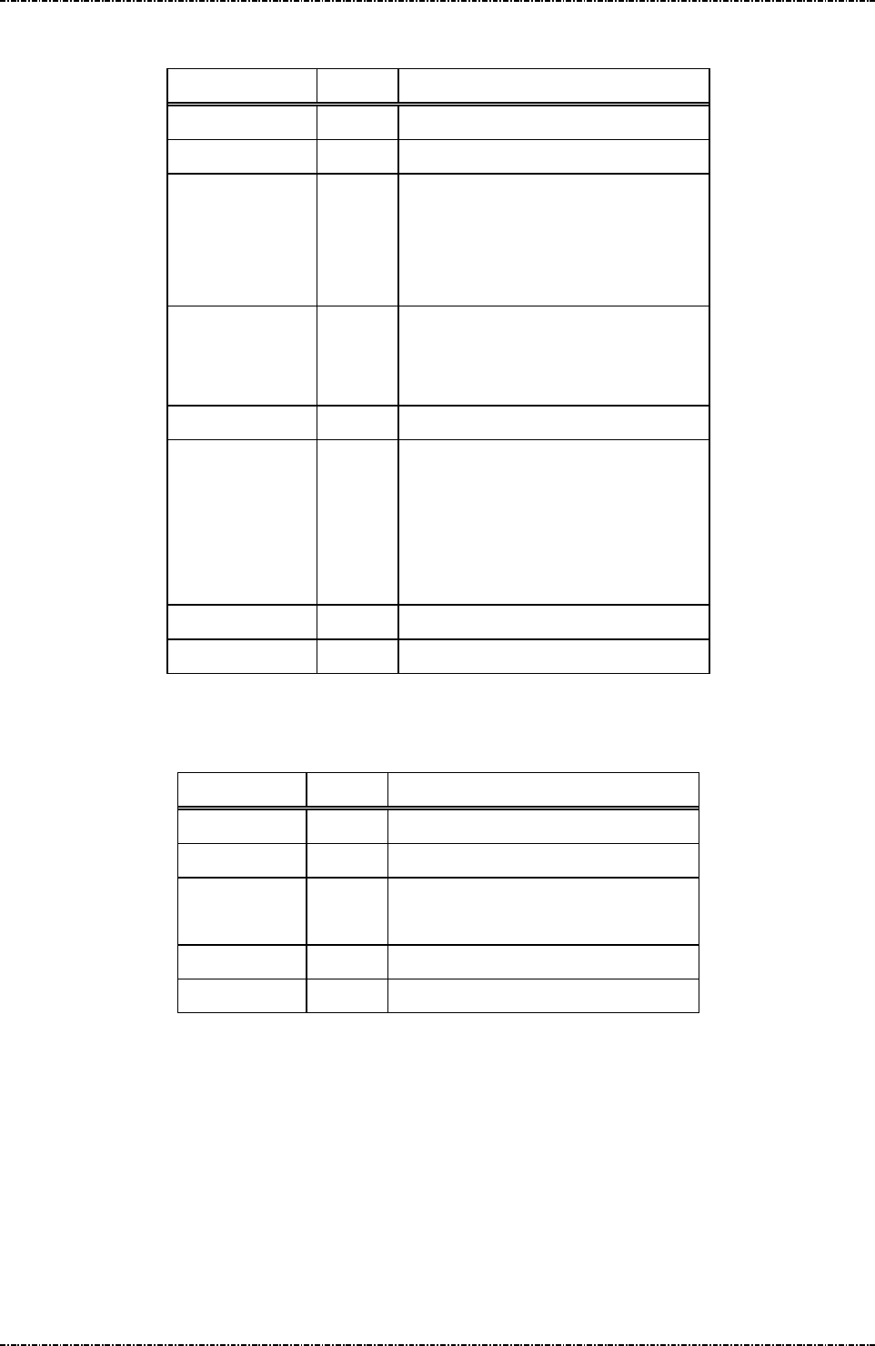
PIN Pad 791 Programmer’s Manual (PCI POS-A) UDN PM0103-U Rev. 06
Section 9 – Online transaction messages with Master / Session keys 2015-04-20
Page213
Uniform Industrial Corp. Proprietary and Confidential Total 342 pages
Z3 request frame (authenticated mode or PIN entry mode)
Field Length
Value and description
<STX> 1 <02>
Z3 2 Message ID
<GS> or <RS> 1 <1D> for authenticated mode
<1E> for PIN entry mode
(In these mode, PIN Pad will clear
screen content.)
[Prompt ID1] 3 Prompt ID that corresponds to fixed
prompt provided by PIN pad.
Decimal string: 001 ~ 999.
<FS> 1 <1C>, field separator
[Prompt ID2..7]
3 Prompt ID that corresponds to fixed
prompt provided by PIN pad.
Decimal string: 001 ~ 999.
Note. <FS> is required between
prompt ID.
<ETX> 1 <03>
[LRC] 1 Checksum
Z3 response frame (authenticated mode)
Field Length
Value and description
<STX> 1 <02>
Z3 2 Message ID
[status] 1 ‘0’: OK
‘1’: Prompt ID not supported.
<ETX> 1 <03>
[LRC] 1 Checksum

PIN Pad 791 Programmer’s Manual (PCI POS-A) UDN PM0103-U Rev. 06
Section 9 – Online transaction messages with Master / Session keys 2015-04-20
Page214
Uniform Industrial Corp. Proprietary and Confidential Total 342 pages
Message flow:
Normal frame
HOST Direction PIN Pad
Message Z3
<ACK> (Good LRC)
<NAK> (Bad LRC)
<EOT> (after 3 NAKs)
Display prompts as required
Authenticated frame
HOST Direction PIN Pad
Message Z3
<ACK> (Good LRC)
<NAK> (Bad LRC)
<EOT> (after 3 NAKs)
Message Z3
(response frame)
<ACK> (Good LRC)
<NAK> (Bad LRC)
<EOT> (after 3 NAKs)
Display string
<EOT> (if received <ACK>)

PIN Pad 791 Programmer’s Manual (PCI POS-A) UDN PM0103-U Rev. 06
Section 9 – Online transaction messages with Master / Session keys 2015-04-20
Page215
Uniform Industrial Corp. Proprietary and Confidential Total 342 pages
Z2 / Z3 Authenticated mode with fixed prompt
To enable message Z42 and Z50, user has to issue Z2 / Z3 message with a prompt ID supported by PIN
pad (See Appendix H). These prompts are verified during Payment Card Industry (PCI) Security
Conformance tests to make sure users will not expose sensitive information (such as PIN) accidentally.
For security reason, to issue authenticated frame of Z2 / Z3 at the first time, the <SUB> flag is mandatory.
After Z2 authenticated mode entered, PIN pad will accept two kind of Z2 packet:
1. Z2 packet in normal mode, without <SUB> flag, and contains only digits (0~9)
2. Z2 packet in authenticated mode, without <SUB> flag.
For example, issue Z2<GS>005<SUB> and Z2<GS>016 will show “PLEASE ENTER DRIVER LICENSE”
on the screen.
Z2 / Z3 PIN entry mode with fixed prompt
To enable Z60, user has to issue Z2 / Z3 message with a prompt ID supported by PIN pad, dedicated for
PIN entry (See Appendix I). These prompts are verified during Payment Card Industry (PCI) Security
Conformance tests to make sure users will not misunderstand PIN entry request as other non-sensitive
data. Also message Z62’s prompt1 and prompt2 will be checked to see if they are listed in this prompt
table. If not, PIN pad will reject Z62.
Any other messages other than Z2, Z3, Z42, Z50, and Z60 or any unsuccessful Z2 / Z3 messages (wrong
prompt ID, format error, Z2 message includes non decimal characters) will make PIN pad to leave Z2 / Z3
authenticated mode to avoid attack.

PIN Pad 791 Programmer’s Manual (PCI POS-A) UDN PM0103-U Rev. 06
Section 9 – Online transaction messages with Master / Session keys 2015-04-20
Page216
Uniform Industrial Corp. Proprietary and Confidential Total 342 pages
Message Z2 Display String with Authentication Code
Format: <STX>Z2<FS>[KeyID][MAC][Mode][string]<SUB><ETX>[LRC]
(Request frame)
<STX>Z2[status]<ETX>[LRC]
(Response frame)
Message length: Variable.
Usage: This command allows acquirer to show free message on screen as prompt for clear
text entry (Z42, Z50) and PIN entry (Z60). PP791 will verify MAC value by the following
rule:
* Collect [Mode] character, [string] (exclude white space, punctuation marks and
digits), and <SUB> character (if exist), as byte array, padding with ASCII ‘0’ (0x30) to
the multiple of 8.
* Use the key specified by [KeyID] and ISO-9797-1 Algorithm 3 to generate message
authentication code for above data.
* Compare the leftmost 4 bytes of MAC value and the one written in the Z2 command.
If MAC value matches, PP791 will display the [string] written in Z2 command.
Note: 1. If Z2 (string with MAC) is used in combination with Z2 (fixed prompt), their mode
character (GS / RS) must be the same; Otherwise PIN pad will reject secondary Z2.
2. PIN pad will temporarily turn off timer display for the first Z2 message it received.
After Z42, Z50, Z60 are performed, [CAN] key is pressed, or any other message
received and processed, PIN pad will turn on the timer display.
Message element :
Z2 with MAC, request frame
Field Length Value and description
<STX> 1 <02>
Z2 2 Message ID
<FS> 1 <1C>, field separator.
[KeyID] 1 ‘B’ ~ ‘E’, key to verify MAC value. The
specified key must have usage ‘M3’ and
mode ‘V’.
[MAC] 8 Message authentication code of following
message (including <SUB> if exist).
[Mode] 1 <GS> (0x1D) for Non-PIN entry.
<RS> (0x1E) for PIN entry.
[string] 1 .. 62 ASCII string to be displayed
<SUB> 1 <1A> (optional)
When <SUB> exists, PIN pad will clear

PIN Pad 791 Programmer’s Manual (PCI POS-A) UDN PM0103-U Rev. 06
Section 9 – Online transaction messages with Master / Session keys 2015-04-20
Page217
Uniform Industrial Corp. Proprietary and Confidential Total 342 pages
screen contents and also reset entry mode.
<ETX> 1 <03>
[LRC] 1 Checksum
Z2 with MAC, response frame
Field Length Value and description
<STX> 1 <02>
Z2 2 Message ID
[status] 1 ‘0’: OK
‘1’: MAC key ID error (out of ‘B’~’E’).
‘2’: MAC key attribute error.
‘3’: MAC value error.
‘4’: Packet format error.
<ETX> 1 <03>
[LRC] 1 Checksum
Message flow:
HOST Direction PIN pad
Message Z2
<ACK> (Good LRC)
<NAK> (Bad LRC)
<EOT> (after 3 NAKs)
Message Z2
(response frame)
<ACK> (Good LRC)
<NAK> (Bad LRC)
<EOT> (after 3 NAKs)
Display string
<EOT> (if received <ACK>)

PIN Pad 791 Programmer’s Manual (PCI POS-A) UDN PM0103-U Rev. 06
Section 9 – Online transaction messages with Master / Session keys 2015-04-20
Page218
Uniform Industrial Corp. Proprietary and Confidential Total 342 pages
Message Z3 Display Line Prompts with Authentication Code
Format: <STX>Z3<FS>[KeyID][MAC][count][Mode][prompt1]<FS>
[prompt2..7]<SUB><ETX>[LRC] (Request frame)
<STX>Z3[status]<ETX>[LRC] (Response frame)
Message length: Variable.
Usage: This command allows acquirer to show free message on screen as prompt for clear
text entry (Z42, Z50) and PIN entry (Z60). PP791 will verify MAC value by the following
rule:
* Collect [Mode] character, [prompt_n] (exclude white space, punctuation marks and
digits), and <SUB> character (if exist), as byte array, padding with ASCII ‘0’ (0x30) to
the multiple of 8.
* Use the key specified by [KeyID] and ISO-9797-1 Algorithm 3 to generate message
authentication code for above data.
* Compare the leftmost 4 bytes of MAC value and the one written in the Z2 command.
If MAC value matches, PP791 will display the [string] written in Z2 command.
Note: 1. If Z3 (string with MAC) is used in combination with Z3 (fixed prompt), their mode
character (GS / RS) must be the same; Otherwise PIN pad will reject secondary Z3.
2. PIN pad will temporarily turn off timer display for the first Z2 message it received.
After Z42, Z50, Z60 are performed, [CAN] key is pressed, or any other message
received and processed, PIN pad will turn on the timer display.
Message element:
Z3 with MAC, request frame
Field Length Value and description
<STX> 1 <02>
Z3 2 Message ID
<FS> 1 <1C>, field separator.
[KeyID] 1 ‘B’ ~ ‘E’, key to verify MAC value. The
specified key must have usage ‘M3’ and
mode ‘V’.
[MAC] 8 Message authentication code of following
message (including <SUB> if exist).
[count] 1 ‘1’ ~ ‘7’, number of following prompts.
[Mode] 1 <GS> (0x1D) for Non-PIN entry.
<RS> (0x1E) for PIN entry.
[prompt1] Var. First string to be displayed.
<FS> 1 <1C>, field separator

PIN Pad 791 Programmer’s Manual (PCI POS-A) UDN PM0103-U Rev. 06
Section 9 – Online transaction messages with Master / Session keys 2015-04-20
Page219
Uniform Industrial Corp. Proprietary and Confidential Total 342 pages
[prompt N]
Var. Second to end string to be displayed. Each
prompt is separated by <FS>.
<SUB> 1 <1A> (optional)
When <SUB> exists, PIN pad will clear
clear screen contents.
<ETX> 1 <03>
[LRC] 1 Checksum
Z3 with MAC, response frame
Field Length Value and description
<STX> 1 <02>
Z3 2 Message ID
[status] 1 ‘0’: OK
‘1’: MAC key ID error (out of ‘B’~’E’).
‘2’: MAC key attribute error.
‘3’: MAC value error.
‘4’: Packet format error.
<ETX> 1 <03>
[LRC] 1 Checksum
Message flow:
HOST Direction PIN pad
Message Z3
<ACK> (Good LRC)
<NAK> (Bad LRC)
<EOT> (after 3 NAKs)
Message Z3
(response frame)
<ACK> (Good LRC)
<NAK> (Bad LRC)
<EOT> (after 3 NAKs)
Display string
<EOT> (if received <ACK>)

PIN Pad 791 Programmer’s Manual (PCI POS-A) UDN PM0103-U Rev. 06
Section 9 – Online transaction messages with Master / Session keys 2015-04-20
Page220
Uniform Industrial Corp. Proprietary and Confidential Total 342 pages
Example to use Z2 / Z3 with Authencation Code.
[Example 1]
3. Use message 02 (ANSI TR31 frame) to load following key to position ‘B’:
BCDE90123456789ABCDE90123456789A, Usage = M3, Mode = V.
4. Assume we want to clear screen and display following string for PIN entry: “AMOUNT 123456.78
ENTER YOUR PIN”.
5. The data for MAC generation (‘A’ to ‘Z’, ‘a’ to ‘z’ and ISO8859-15 high page character from 0xBC
to 0xFF, padded with ASCII 0):
<RS>AMOUNTENTERYOURPIN<SUB>0000
1E414D4F554E54454E544552594F555250494E1A30303030
The white spaces and digits are not counted into MAC, this feature enables acquirer to issue PIN
entry prompts with different amount, but keep the same MAC value.
6. Use the key specified in the step 1 to calculate ISO9797-1 algorithm 3 MAC.
The result is: C51401D727D761E2.
Take leftmost 4 bytes as MAC value: C51401D7.
7. Send <02>Z2<1C>BC51401D7<1E>AMOUNT 123456.78 ENTER YOUR PIN<1A><03> to PIN
Pad, Then message Z60 can be issued to request PIN entry.
8. Send <02>Z2<1C>BC51401D7 <1A>AMOUNT 123.45 ENTER YOUR PIN<03> to PIN Pad to see
the same MAC applies to different amounts.
[Example 2]
1. Use message 02 (ANSI TR31 frame) to load following key to position ‘B’:
6AC292FAA1315B4D8234B3A3D7D5933A, Usage = M3, Mode = V.
2. Assume we want to clear screen and display for non-PIN entry: “MESSAGE ONE 1.0” and
“MESSAGE TWO 2.0”.
3. The data for MAC generation (padded with ASCII 0):
<GS>MESSAGEONE<FS>MESSAGETWO<SUB>0
1D4D4553534147454F4E451C4D45535341474554574F1A30
4. Use the key specified in the step 1 to calculate ISO9797-1 algorithm 3 MAC.
Take leftmost 4 bytes as MAC value: 22C0BAD9.
5. Send <02>Z3<1C>B22C0BAD92<1D>MESSAGE ONE 1.0<1C>MESSAGE TWO 2.0<1A><03>
to PIN pad.
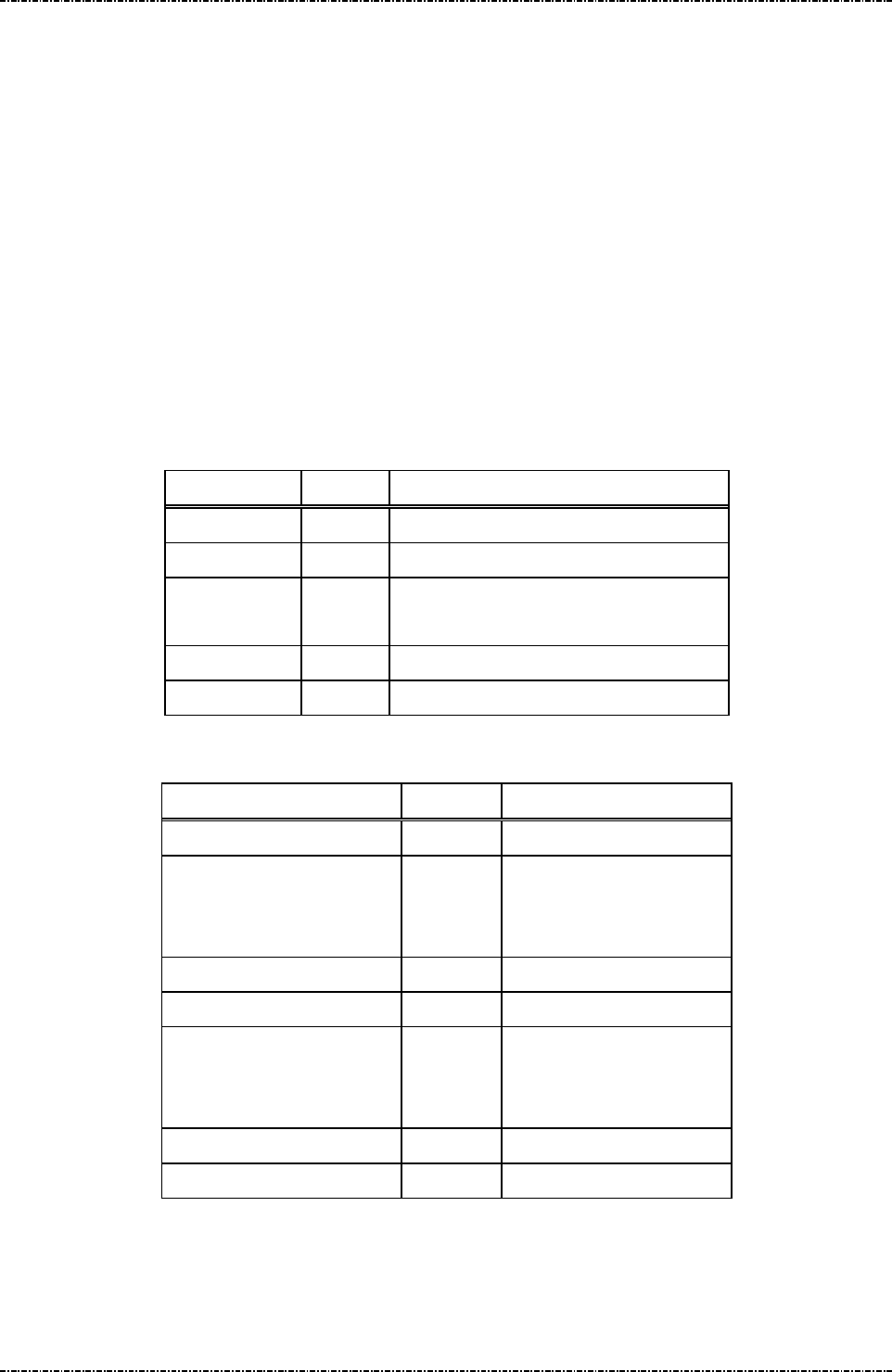
PIN Pad 791 Programmer’s Manual (PCI POS-A) UDN PM0103-U Rev. 06
Section 9 – Online transaction messages with Master / Session keys 2015-04-20
Page221
Uniform Industrial Corp. Proprietary and Confidential Total 342 pages
Message Z42 Read Key Code
Format: <STX>Z42[timeout]<ETX>[LRC]
Message length: Variable 6 to 9 bytes.
Usage: Once PP791 receives this command, it begins polling functional key array until timeout.
If PP791 received Z2 / Z3 authenticated frame before Z42, it will return any key
pressed by user by ASCII key codes via message Z43. Else it will return only function
key codes (F1, F2, F3, CAN, CLR, ENTER), and reject numerical key (0 to 9). Multiple
key press or combined key press will be discarded.
Abort input: Issue message 72 to abort the operation.
Note: Z2/Z3 required: Because Z42 will not show any message to prompt user operation, Z2
or Z3 should be issued before this command, or PIN pad will send <EOT> and stop.
Message element:
Field Length
Value and description
<STX> 1 <02>
Z42 3 Message ID
[timeout] 1 to 3 ASCII character from 1 to 255, for
example “10” means 10 seconds timeout.
<ETX> 1 <03>
[LRC] 1 Checksum
Message flow:
HOST Direction PP791
Message Z2 or Z3
<ACK> (Good LRC)
<NAK> (Bad LRC)
<EOT> (after 3 NAKs)
Show prompt message
Message Z42
<ACK> (Good LRC)
<NAK> (Bad LRC)
<EOT> (after 3 NAKs)
Message Z43
<ACK>/<NAK>/<EOT>

PIN Pad 791 Programmer’s Manual (PCI POS-A) UDN PM0103-U Rev. 06
Section 9 – Online transaction messages with Master / Session keys 2015-04-20
Page222
Uniform Industrial Corp. Proprietary and Confidential Total 342 pages
Message Z43 Read Key Code Response
Format: <STX>Z43[Keycode]<ETX>[LRC]
Message length: Fixed 7 bytes.
Usage: This is the response frame of Z42.
Message element:
Field Length
Value and description
<STX> 1 <02>
Z43 3 Message ID
[keycode]
1 ‘0’ to ‘9’
ASCII ‘A’ to ‘C’ denotes 3 function
keys.
‘A’ = [F1]
‘B’ = [F2]
‘C’ = [F3]
‘*’ = [CAN]
‘#’ = [ENTER]
‘/’ = [CLR]
‘?’ means time out.
<ETX> 1 <03>
[LRC] 1 Checksum
Message flow:
(Please refer to message Z42)

PIN Pad 791 Programmer’s Manual (PCI POS-A) UDN PM0103-U Rev. 06
Section 9 – Online transaction messages with Master / Session keys 2015-04-20
Page223
Uniform Industrial Corp. Proprietary and Confidential Total 342 pages
Message Z50 String Entry Request
Format: <STX>Z50[echo flag][timeout][max entry]<ETX>[LRC]
Message length: Variable 10 to 12 bytes.
Usage: Request user to input string on keypad.
Then PP791 will wait for keypad input and store ASCII data into internal buffer. To
input English character on the keypad, press [F2] key to rotate the last character. For
example, press [1], [F2], [F2] will input a ‘Z’ character into PP791. The maximum
length of internal buffer is 49 characters.
User can use [CLR] to clear input buffer and input again, or [CAN] to cancel input.
Press ‘0’ and press [F2] will transform ‘0’ into period or white space.
Abort input: Issue message 72 to abort the operation.
Note: A Z2 or Z3 message with authenticated frame must be issued before Z50. Otherwise
PIN pad will refuse to execute.
Message element:
Field Length
Value and description
<STX> 1 <02>
Z50 3 Message ID
[echo flag] 1 ‘0’: echo input as ‘*’
‘1’: echo input as is
‘2’: do not echo
[timeout] 3 ASCII character from 1 to 255 to set the
timeout for each keypress, for example
“010” means 10 seconds timeout after
the last keypress.
[max entry] 1 or 2 (optional) Maximum entry count.
Range from 00 to 49 (or 0 to 49)
<ETX> 1 <03>
[LRC] 1 Checksum
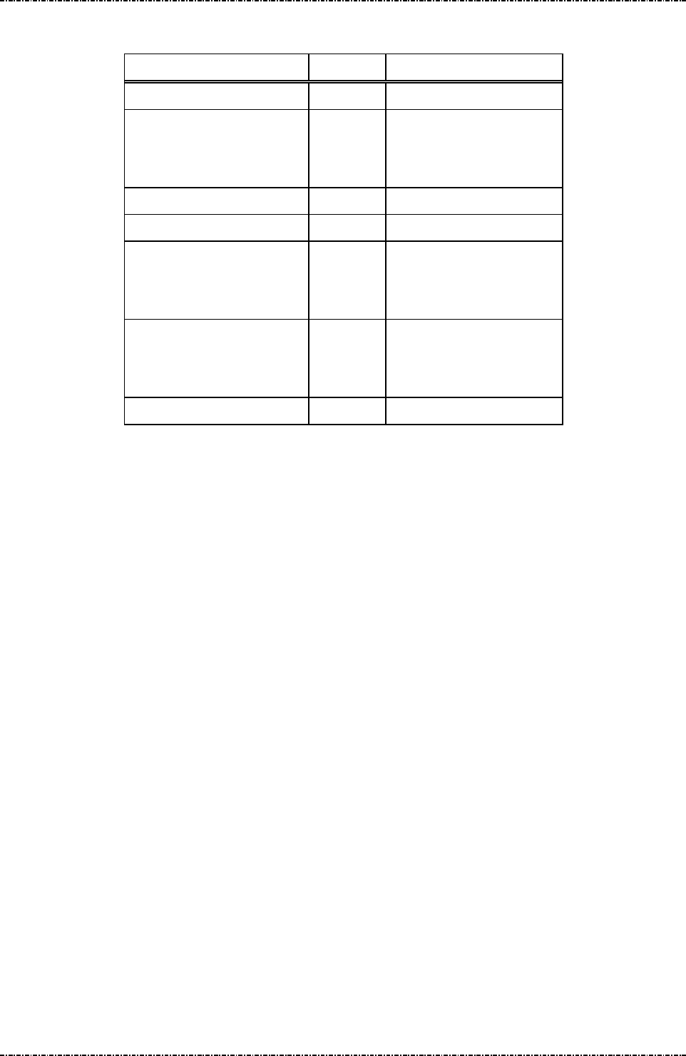
PIN Pad 791 Programmer’s Manual (PCI POS-A) UDN PM0103-U Rev. 06
Section 9 – Online transaction messages with Master / Session keys 2015-04-20
Page224
Uniform Industrial Corp. Proprietary and Confidential Total 342 pages
Message flow:
HOST Direction PP791
Message Z2 or Z3
<ACK> (Good LRC)
<NAK> (Bad LRC)
<EOT> (after 3 NAKs)
Show prompt message
Message Z50
<ACK> (Good LRC)
<NAK> (Bad LRC)
<EOT> (after 3 NAKs)
Message Z51
(or <EOT> when input
cancelled)
<ACK>/<NAK>/<EOT>

PIN Pad 791 Programmer’s Manual (PCI POS-A) UDN PM0103-U Rev. 06
Section 9 – Online transaction messages with Master / Session keys 2015-04-20
Page225
Uniform Industrial Corp. Proprietary and Confidential Total 342 pages
Message Z51 String Entry Response
Format: <STX>Z51[string]<ETX>[LRC]
Message length: Variable, maximum 55 bytes.
Usage: This is the response frame of Z50.
Message element:
Field Length
Value and description
<STX> 1 <02>
Z51 3 Message ID
[string] 1..49 User inputted string.
‘?’ means time out.
<ETX> 1 <03>
[LRC] 1 Checksum
Message flow:
(Please refer to message Z50)

PIN Pad 791 Programmer’s Manual (PCI POS-A) UDN PM0103-U Rev. 06
Section 9 – Online transaction messages with Master / Session keys 2015-04-20
Page226
Uniform Industrial Corp. Proprietary and Confidential Total 342 pages
Message Z60 PIN entry request with external prompt (MK/SK)
Format: <STX>Z60.[account]<FS>[session key]<FS>[timeout]<ETX>[LRC]
Message length: Variable 32 to 43 bytes (max. 59 bytes for TDES session key).
Usage: Request the PIN pad to accept customer PIN entry and encrypt it using the account
number and working key sent along in this message. The encrypted PIN block should
be retrieved via message 71.
Note: Z2/Z3 (PIN entry mode) required: Message Z2 or Z3 (PIN entry mode) should be
issued before this command, or PIN pad will send <EOT> and stop.
Aborting Transaction: Please refer to message 70.
PIN length: Please refer to message 70.
Master key must be selected before transaction: Please refer to message 70.
Triple DES capability: Please refer to message 70.
Session Key: If the selected key is with usage “P0”, the session key should be all
zeros.
Message element:
Field Length
Value and description
<STX> 1 <02>
Z60 3 Message ID
. 1 <2E>, delimiter
[Account] 8 .. 19 Account number
<FS> 1 <1C>, Field separator
[Session key] 16 or
32
Session key encrypted with selected master
key. 32-characters session key produces
TDES encrypted PIN block with EDE
order.
Format: hexadecimal string.
This filed should be all zeros if the selected
key is with usage “P0”
<FS> 1 (Optional) <1C>, Field separator
[timeout] 1 (Optional) ASCII character from ‘1’ to ‘9’
which is the timeout value in the unit of 30
seconds. Default = 9x30 = 270 seconds.
<ETX> 1 <03>
[LRC] 1 Checksum

PIN Pad 791 Programmer’s Manual (PCI POS-A) UDN PM0103-U Rev. 06
Section 9 – Online transaction messages with Master / Session keys 2015-04-20
Page227
Uniform Industrial Corp. Proprietary and Confidential Total 342 pages
Message flow:
HOST Direction
PIN pad
Message Z2 or Z3
<ACK> (Good LRC)
<NAK> (Bad LRC)
<EOT> (after 3 NAKs)
Show prompt message
Message Z60
<ACK> (Good LRC)
<NAK> (Bad LRC)
<EOT> (after 3 NAKs)
Message 71
(after customer PIN entered), or
<EOT> when input timed out or
user pressed [CAN]
<ACK> (Good LRC)
<NAK> (Bad LRC)
<EOT> (after 3 NAKs)

PIN Pad 791 Programmer’s Manual (PCI POS-A) UDN PM0103-U Rev. 06
Section 9 – Online transaction messages with Master / Session keys 2015-04-20
Page228
Uniform Industrial Corp. Proprietary and Confidential Total 342 pages
Message Z62 PIN entry request with customized prompt (MK/SK)
Format: <STX>Z62.[account]<FS>[session key][minPIN][maxPIN]
[null flag][prompt1]<FS>[prompt2]<FS>[proc prompt]<FS>
[timeout]<ETX>[LRC]
Message length: Variable 39 to 100 bytes (max. 116 bytes for TDES session key).
Usage: Request the PIN pad to display the prompt message in this data frame, accept
customer PIN entry and encrypt it using the account number and working key sent
along in this message. Display the [proc prompt] when the PIN has been entered. The
encrypted PIN block should be retrieved via message 71.
NOTE: Z2/Z3 (PIN entry mode) required: If the [prompt1], [prompt2] and [proc prompt]
contains any string not listed in Appendix I (fixed prompt table for PIN entry), PIN pad
will send <EOT> and stop.
Aborting Transaction: Please refer to message 70.
PIN length: Although Z62 allow programmer to specify the maximum and minimum
PIN length, but it is not allowed to set the value of [maxPIN] and [minPIN] to exceed
ANSI x9.8 specification except allow null PIN.
Master key must be selected before transaction: Please refer to message 70.
Triple DES capability: Please refer to message 70.
Session Key: If the selected key is with usage “P0”, the session key should be all
zeros.

PIN Pad 791 Programmer’s Manual (PCI POS-A) UDN PM0103-U Rev. 06
Section 9 – Online transaction messages with Master / Session keys 2015-04-20
Page229
Uniform Industrial Corp. Proprietary and Confidential Total 342 pages
Message element:
Field Length
Value and description
<STX> 1 <02>
Z62 3 Message ID
. 1 <2E>, delimiter
[account] 8 .. 19 Account number
<FS> 1 <1C>, field separator
[session key] 16 or
32
Session key encrypted with selected master key.
32-characters session key produces TDES encrypted
PIN block with EDE order.
Format: hexadecimal string.
This filed should be all zeros if the selected key is with
usage “P0”
[minPIN] 2 00, 04 .. 12 minimum PIN length.
('00' only available when [null flag] set to 'Y').
[maxPIN] 2 00, 04 .. 12 maximum PIN length.
('00' only available when [null flag] set to 'Y').
[null flag] 1 Y Null PIN allowed
N Null PIN not allowed
[prompt1] 1 .. 16 Prompt displayed before any key is pressed, alternate
with prompt2
<FS> 1 <1C>, field separator
[prompt2] 1…16 (optional)Prompt displayed before any key is pressed,
alternate with prompt1
<FS> 1 <1C>, field separator
[proc prompt] 1…16 (optional)Prompt displayed after PIN is entered
<FS> 1 (optional) <1C>, field separator
[timeout] 1 (optional) ASCII character from ‘1’ to ‘9’ which is the
timeout value in the unit of 30 seconds. Default = 9x30
= 270 seconds.
<ETX> 1 <03>
[LRC] 1 Checksum

PIN Pad 791 Programmer’s Manual (PCI POS-A) UDN PM0103-U Rev. 06
Section 9 – Online transaction messages with Master / Session keys 2015-04-20
Page230
Uniform Industrial Corp. Proprietary and Confidential Total 342 pages
Message flow:
HOST Direction PIN pad
Message Z62
<ACK> (Good LRC)
<NAK> (Bad LRC)
<EOT> (after 3 NAKs)
(Display [prompt1] and [prompt2] wait for
user enter PIN)
Message 71
(after customer PIN entered)
<ACK> (Good LRC)
<NAK> (Bad LRC)
<EOT> (after 3 NAKs)
(Display [proc prompt])

PIN Pad 791 Programmer’s Manual (PCI POS-A) UDN PM0103-U Rev. 06
Section 9 – Online transaction messages with Master / Session keys 2015-04-20
Page231
Uniform Industrial Corp. Proprietary and Confidential Total 342 pages
Message Z66 Message Authentication Code (MAC) Request
Format: <STX>Z66[PktType][SeqNo][KeyId] <FS> [SessionKey] <FS> [SecKeyId]
<FS> [Message] <ETX> [LRC]
Message length: Variable 14 to 270 bytes.
Usage: This message is used to generate MAC codes according to algorithm specified in ANSI
X9.19 (ISO 9797-1). User can send ASCII strings or hexadecimal strings to PP791 by
Z66 message to generate its MAC. User can also separate a long message into
multiple Z66 messages with increasing sequence number to generate a MAC.
NOTE: Message Length: Onetime message can be up to 224 characters (equal to 112bytes
when send as hexadecimal string because 2 characters represents 1 bytes). Multiple
messages can have sequence number from 00 to 99, thus the maximum capacity of
Z66 message is 22400 characters (or 11200 bytes in binary mode).
Multiple messages: When using multiple messages, [KeyId] and [SessionKey] and
[SecKeyId] must be the same. [Message] must be the multiple of 8 characters (or 16
characters in binary mode). Or PP791 will generate a wrong MAC.
MAC algorithm: PP791 generate TDES MAC according to ISO9797-1 algorithm 3.
(Padding with 0. Initial vector = 0. Refer to Appendix A point 10 for detail algoritgm.)
Session Key: The value of session key relates to the usage of specified master keys.
Usage of 1st
Key ID
Usage of 2nd
Key ID
Value of session key MAC Key
“K0” N/A Non-zero Session key
“M3”
(mode G)
N/A Zero Master key specified by
[KeyId].
If specified key is mode ‘V’,
this is for MAC verification
and cannot used to generate
MAC for Z66 command.
“M1”
(mode G)
“M1” Zero Master key specified by
[KeyId] as left key, and
master key specified by
[SecKeyId] as right key.

PIN Pad 791 Programmer’s Manual (PCI POS-A) UDN PM0103-U Rev. 06
Section 9 – Online transaction messages with Master / Session keys 2015-04-20
Page232
Uniform Industrial Corp. Proprietary and Confidential Total 342 pages
Message element:
Field Length
Value and description
<STX> 1 <02>
Z66 3 Message ID
[PktType] 1 '4' = ASCII last or only packet.
'5' = ASCII first or middle of multiple packets.
'6' = Binary last or only packet.
'7' = Binary first or middle of multiple packets.
[SeqNo] 2 '00' to '99', for onetime only packet, set to 00.
[KeyId] 1 (Optional) Master key to use, range = 'B' to 'E'. If this
filed is blank, the MAC master key will be the selected
key 0 ~ 9.
<FS> 1 <1C>, field separator
[SessionKey] 32 Session key will be decrypted by: Master key pointed
by [KeyId].
Format: hexadecimal string.
This filed should be all zeros if the selected key is with
usage “M1” or “M3”
<FS> 1 <1C>, field separator
[SecKeyId] 1 (Optional) Refer to note of Z66 usage. If first [KeyId]
points to key with “K0” or “M3” usage, this field
should be omitted.
<FS> 1 <1C>, field separator
[Message] 1-224 ASCII string or Hexadecimal string to be MACed.
<ETX> 1 <03>
[LRC] 1 Checksum
Message flow: (Onetime only packets)
HOST Direction PIN pad
Message Z66 (type 4,6)
<ACK> (Good LRC)
<NAK> (Bad LRC)
<EOT> (after 3 NAKs)
Message Z67 (with MAC)
<ACK> (Good LRC)
<NAK> (Bad LRC)
<EOT> (after 3 NAKs)

PIN Pad 791 Programmer’s Manual (PCI POS-A) UDN PM0103-U Rev. 06
Section 9 – Online transaction messages with Master / Session keys 2015-04-20
Page233
Uniform Industrial Corp. Proprietary and Confidential Total 342 pages
Message flow: (Multiple packets)
HOST Direction PIN pad
Message Z66
(Seq'00' and type 5,7)
<ACK> (Good LRC)
<NAK> (Bad LRC)
<EOT> (after 3 NAKs)
Message Z67 (with status code '1')
<ACK> / <NAK> /
<EOT>
Message Z66
(Seq'01'--'98', type 5,7)
<ACK> / <NAK> / <EOT>
Message Z67 (with status code '1')
………………… …….. …………………………………..
Message Z66
(Sequence# larger than
last packet, type 4,6)
<ACK> / <NAK> / <EOT>
Message Z67 (with MAC)
<ACK> / <NAK> /
<EOT>

PIN Pad 791 Programmer’s Manual (PCI POS-A) UDN PM0103-U Rev. 06
Section 9 – Online transaction messages with Master / Session keys 2015-04-20
Page234
Uniform Industrial Corp. Proprietary and Confidential Total 342 pages
Message Z67 Message Authentication Code (MAC) Response
Format: <STX>Z67[status][MAC]<ETX>[LRC]
Message length: Fixed 7 (status only) or 23 (with MAC) bytes.
Usage: PP791 generated MAC calculation response. It contains status codes or MAC.
Message element:
Field Length
Value and description
<STX> 1 <02>
Z67 3 Message ID
[status] 1 '0'=Success, MAC follows
'1'=Ready for next Z66 packet, user in
multiple messages.
'2'=Sequence numbers out of order
'3'=Master key specified in [KeyId] not exist,
or range unacceptable (id 0 to A), or
usage not “K0”, “M1”, “M3.
'4'=Master key specified in [SecKeyId]
unreasonable or not exist.
The [SecKeyId] only exists if [KeyId]
points to a “M1” master key, and the
[SecKeyId] itself should have “M1”
usage.
'5'=[Message] length have error (too long,
zero length, or not even number in binary
mode)
'6'=[PkyType] flag has invalid value
'7'=[Message] contents error (i.e. characters
larger than 'F' in binary mode)
'8'=[SessionKey] invaild
‘9’=MAC master key length should not be 8
‘A’=Session key is incompatible to the usage
of specified master key.
(If MK’s usage is “M1” or “M3”, SK
should contains all zero, if MK’s usage is
“K0”, SK should not be zero.)
[MAC] 16 Calculated MAC.
<ETX> 1 <03>
[LRC] 1 Checksum

PIN Pad 791 Programmer’s Manual (PCI POS-A) UDN PM0103-U Rev. 06
Section 9 – Online transaction messages with Master / Session keys 2015-04-20
Page235
Uniform Industrial Corp. Proprietary and Confidential Total 342 pages
Message flow:
(Please refer to message Z66)
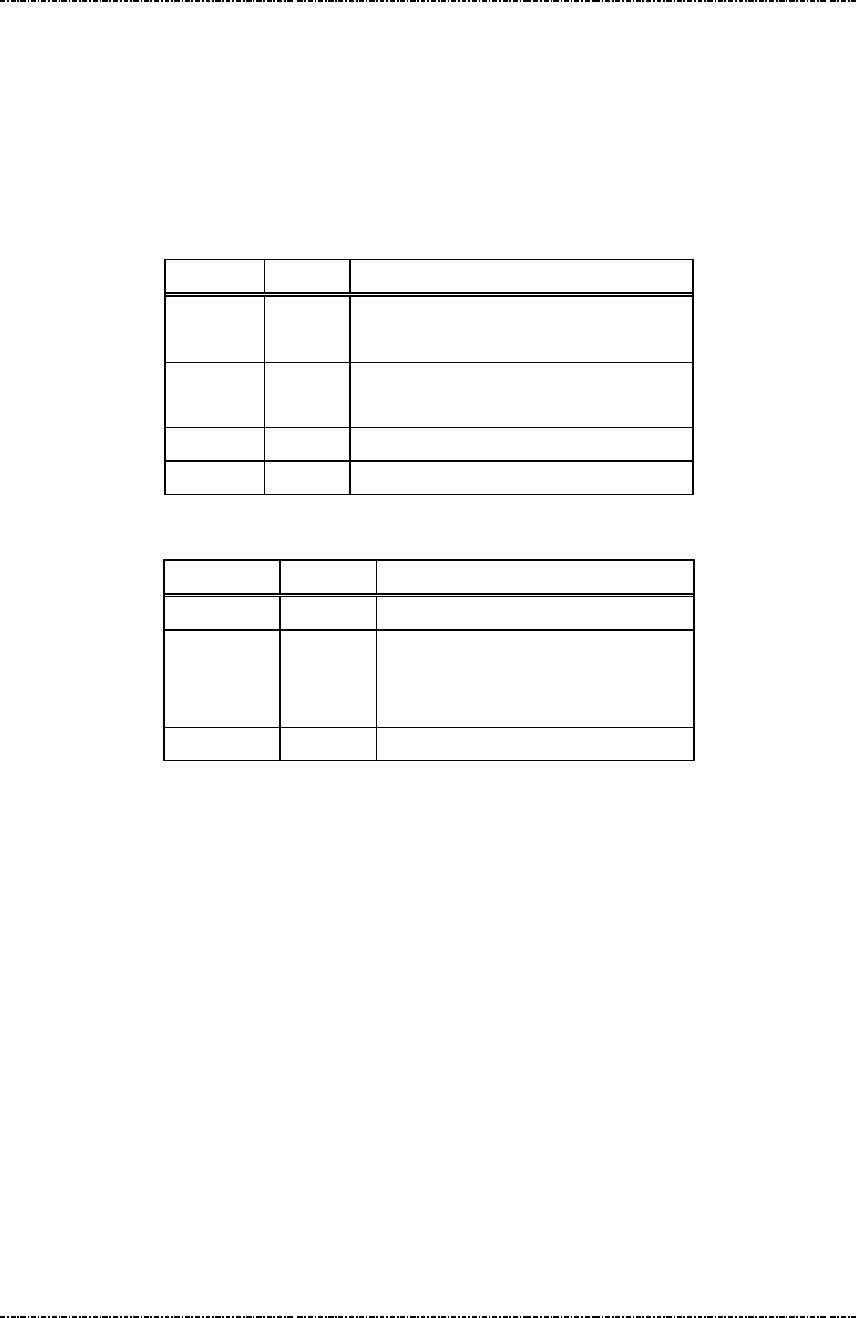
PIN Pad 791 Programmer’s Manual (PCI POS-A) UDN PM0103-U Rev. 06
Section 9 – Online transaction messages with Master / Session keys 2015-04-20
Page236
Uniform Industrial Corp. Proprietary and Confidential Total 342 pages
Message Z7 Turn ON/OFF CANCEL Message Display
Format: <STX>Z7[option]<ETX>[LRC]
Message length: Fixed 6 bytes.
Usage: When a CANCEL message received or a CANCEL key pressed to cancel a current
transaction, the PIN pad will display a “TRANSACTION CANCELLED” message. This
could be turned ON or OFF using message Z7.
Message element:
Field Length
Value and description
<STX> 1 <02>
Z7 2 Message ID
[option] 1 ‘0’ = message displayed
‘1’ = message not displayed
<ETX> 1 <03>
[LRC] 1 Checksum
Message flow:
HOST Direction PIN pad
Message Z7
<ACK> (Good LRC)
<NAK> (Bad LRC)
<EOT> (after 3 NAKs)
message turned ON/OFF

PIN Pad 791 Programmer’s Manual (PCI POS-A) UDN PM0103-U Rev. 06
Section 9 – Online transaction messages with Master / Session keys 2015-04-20
Page237
Uniform Industrial Corp. Proprietary and Confidential Total 342 pages
Message Z8 Set Idle Prompt
Format: <STX>Z8[prompt]<ETX>[LRC]
Message length: Variable 6 to 21 bytes.
Usage: The PIN pad will display an idle prompt when it is in IDLE state. HOST can change this
idle prompt via message Z8. If the prompt field is filled with a null string, then the PIN
pad will use the default prompt afterwards.
Message element:
Field Length
Value and description
<STX> 1 <02>
Z8 2 Message ID
[Prompt] 1 .. 16
Idle prompt to be used
<ETX> 1 <03>
[LRC] 1 Checksum
Message flow:
HOST Direction
PIN pad
Message Z8
<ACK> (Good LRC)
<NAK> (Bad LRC)
<EOT> (after 3 NAKs)
Displays idle prompt

PIN Pad 791 Programmer’s Manual (PCI POS-A) UDN PM0103-U Rev. 06
Section 10 – Online transaction messages with DUKPT 2015-04-20
Page238
Uniform Industrial Corp. Proprietary and Confidential Total 342 pages
Section 10 Online transaction messages with Derived Unique
Key per Transaction (DUKPT)
The following messages are designed for Derived Unique Key Per Transaction (DUKPT) key
management scheme described in ANSI X9.24-1992 and 2002 (Triple-DES DUKPT).
Note that some of the messages have the same IDs as those in MK/SK scheme, but with different
message format.
[TDES Capability]
If PP791 receives double length key in message 90/94 (Load Initial Key), the following DUKPT operation
will be done in TDES mode. PIN block will be TDES encrypted by derived key in EDE order.
[Secondary DUKPT Key Set]
PP791 provides 2nd key set of DUKPT operation for scalability. For example, customer can inject a DES
initial key into key set 0 and a TDES initial key into key set 1, using key set 0 to process traditional DES
transactions at first. When host systems ready to shift to TDES transaction, simply issue key set
selection command (96) to make PP791 switch to key set 1 without recall all PP791 to inject new initial
keys.
The following messages fall into this category:
60 Pre-Authorization PIN Entry Request
62 Pre-Authorization Amount Authorization Request
63 Pre-Authorization Amount Authorization Response
70 PIN entry request
71 Encrypted PIN block response
72 PIN entry cancel
Z60 PIN entry request with external prompt (DUKPT)
Z62 PIN entry request with customized prompt
76 PIN Entry Test Request
90 Load First Initial Key Request
91 Load Initial Key Response
94 Load Second Initial Key Request
96 Select Active Key Set

PIN Pad 791 Programmer’s Manual (PCI POS-A) UDN PM0103-U Rev. 06
Section 10 – Online transaction messages with DUKPT 2015-04-20
Page239
Uniform Industrial Corp. Proprietary and Confidential Total 342 pages
Message 60 Pre-authorization PIN Entry Request
Format: <STX>60[account] <ETX>[LRC]
Message length: Variable 13 to 24 bytes.
Usage: PIN pad will wait till the PIN entered and ENTER key is pressed. After PIN is entered,
message 71 with PIN block will be sent as response. The HOST must transmit
message 62 to ask for confirmation on transaction amount.
Note: Z2/Z3 (PIN entry mode) required: Message Z2 or Z3 (PIN entry mode) should be
issued before this command, or PIN pad will send <EOT> and stop.
Aborting Transaction: Please refer to message 70(DUKPT).
PIN length: Please refer to message 70(DUKPT).
Message element:
Field Length
Value and description
<STX> 1 <02>
60 2 Message ID
[Account] 8..19 Primary account number
<ETX> 1 <03>
[LRC] 1 Checksum

PIN Pad 791 Programmer’s Manual (PCI POS-A) UDN PM0103-U Rev. 06
Section 10 – Online transaction messages with DUKPT 2015-04-20
Page240
Uniform Industrial Corp. Proprietary and Confidential Total 342 pages
Message flow:
HOST Direction
PIN pad
Message Z2 or Z3
<ACK> (Good LRC)
<NAK> (Bad LRC)
<EOT> (after 3 NAKs)
Show Prompt Messages
Message 60
<ACK> (Good LRC)
<NAK> (Bad LRC)
<EOT> (after 3 NAKs)
(User enter PIN and press ENTER)
Message 71
<ACK> (Good LRC)
<NAK> (Bad LRC)
<EOT> (after 3 NAKs)
Display “PIN PAD PROCESSING”
until CLEAR pressed or another
message received.
Message 62
<ACK> (Good LRC)
<NAK> (Bad LRC)
<EOT> (after 3 NAKs)
(User confirm the amount)
Message 63
<ACK> (Good LRC)
<NAK> (Bad LRC)
<EOT> (after 3 NAKs)
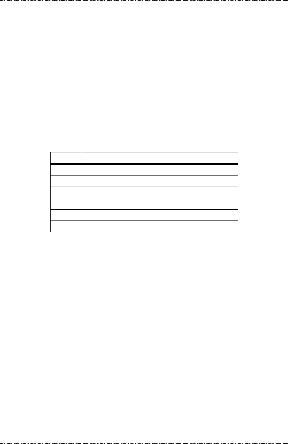
PIN Pad 791 Programmer’s Manual (PCI POS-A) UDN PM0103-U Rev. 06
Section 10 – Online transaction messages with DUKPT 2015-04-20
Page241
Uniform Industrial Corp. Proprietary and Confidential Total 342 pages
Message 62 Pre-authorization Amount Authorization Request
Format: <STX>62[DC Ind][amount]<ETX>[LRC]
Message length: Variable 10 to 14 bytes.
Usage: Display prompt and accept customer PIN input. The following prompt will be displayed:
“Total Amount $xxx.xx”
“Enter – Confirm”
”Cancel – Decline”
xxx.x is the content of Amount field, with length between 4 to 8 positions. The PIN pad
will then wait till either CAN or ENTER key is pressed. If ENTER key is pressed, the
PIN pad will response with positive confirmation. If CAN is pressed, the PIN pad will
response a negative confirmation. During this period, the PIN pad will not process any
message other than the message 72(cancel transaction).
Message element:
Field Length
Value and description
<STX> 1 <02>
62 2 Message ID
[DC Ind]
1 D/C: Debit/Credit Indicator
[amount]
4..8 Amount of goods to be displayed on PIN pad.
<ETX> 1 <03>
[LRC] 1 Checksum
Message flow:
Please reference message 60.

PIN Pad 791 Programmer’s Manual (PCI POS-A) UDN PM0103-U Rev. 06
Section 10 – Online transaction messages with DUKPT 2015-04-20
Page242
Uniform Industrial Corp. Proprietary and Confidential Total 342 pages
Message 63 Pre-authorization Amount Authorization Response
Format: <STX>63[Confirm] <ETX>[LRC]
Message length: Fixed 6 bytes.
Usage: Send Authentication Code and the confirmation of transaction amount to HOST.
Message element:
Field Length
Value and description
<STX> 1 <02>
63 2 Message ID
[Confirm] 1 ‘0’ OK, ‘1’ denied.
<ETX> 1 <03>
[LRC] 1 Checksum
Message flow:
Please reference message60.

PIN Pad 791 Programmer’s Manual (PCI POS-A) UDN PM0103-U Rev. 06
Section 10 – Online transaction messages with DUKPT 2015-04-20
Page243
Uniform Industrial Corp. Proprietary and Confidential Total 342 pages
Message 70 PIN Entry Request (DUKPT)
Format: <STX>70[account]<FS>[DC Ind][amount]<FS>[timeout]<ETX>[LRC]
Message length: Variable 21 to 36 bytes.
Usage: Display prompt and accept customer PIN input. The following prompt will be displayed:
"Total Amount"
"$xxx.xx"
"Enter PIN"
"Push "ENTER""
xxx.x is the content of Amount field, with length between 4 to 8 positions. The PIN pad
will then wait till the PIN entered and [ENTER] key is pressed. After ENTER key is
pressed, the string “PIN PAD” and “PROCESSING” will be displayed until the CLEAR
key is pressed. During this period, the PIN Pad will not process any message other
than the CANCEL message (message 72).
NOTE: Aborting transaction: Press CLEAR button to reset the PIN input and CAN (cancel)
button to abort the transaction.
PIN length: According to ANSI X9.8 standard, the length of PIN should between 4 to
12 digits. If user inputs less than 4 digits and press ENTER, PIN pad will beep for error
and continue to wait for user’s input. When user inputs 13th character, PIN pad will
beep for error, conserves PIN character 1st to 12th, and wait for ENTER.
Triple DES capability: If preloaded initial key is double length key, PP791 will produce
TDES encrypted PIN block (EDE order).
Message element:
Field Length Value and description
<STX> 1 <02>
70 2 Message ID
[Account] 8..19 Primary account number
<FS> 1 <1C>, field separator
[DC Ind] 1 D/C: Debit/Credit Indicator
[Amount] 4..8 Amount of goods to be displayed on PIN pad.
<FS> 1 (optional) <1C>, field separator
[timeout] 1 (optional) ASCII character from ‘1’ to ‘9’ which
is the timeout value in the unit of 30 seconds.
Default = 9x30 = 270 seconds.
<ETX> 1 <03>
[LRC] 1 Checksum

PIN Pad 791 Programmer’s Manual (PCI POS-A) UDN PM0103-U Rev. 06
Section 10 – Online transaction messages with DUKPT 2015-04-20
Page244
Uniform Industrial Corp. Proprietary and Confidential Total 342 pages
Message flow:
HOST Direction PIN pad
Message 70
<ACK> (Good LRC)
<NAK> (Bad LRC)
<EOT> (after 3 NAKs)
Message 71 or
<EOT> when [CAN] pressed or input
timed out.
<ACK> (Good LRC)
<NAK> (Bad LRC)
<EOT> (after 3 NAKs)
Display “PIN PAD PROCESSING”
until CLEAR pressed or another
message received.
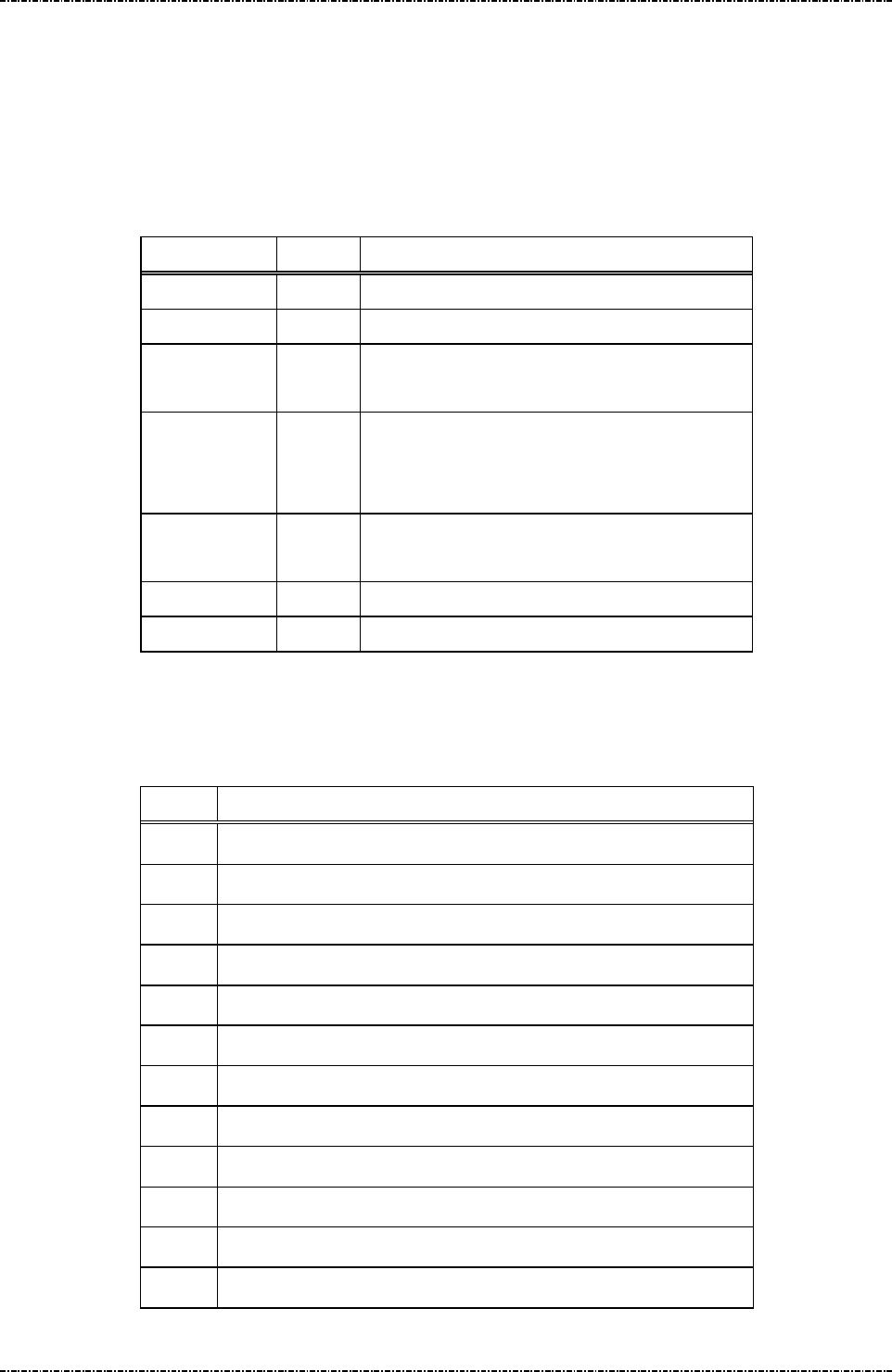
PIN Pad 791 Programmer’s Manual (PCI POS-A) UDN PM0103-U Rev. 06
Section 10 – Online transaction messages with DUKPT 2015-04-20
Page245
Uniform Industrial Corp. Proprietary and Confidential Total 342 pages
Message 71 Encrypted PIN Block Response
Format: <STX>71<fkey flag>[Key Serial#][PIN][LRC] (PIN block frame)
<STX>71[error code]<ETX>[LRC] (Error code frame)
Message length: Variable 32 to 42 bytes.
Usage: Send the entered PIN to HOST in encrypted format.
Message element:
Field Length
Value and description
<STX> 1 <02>
71 2 Message ID
[fkey flag] 1 Always ‘0’ (This field is kept to retain old
model compatibility.)
[Key Serial#]
10..20 Key Serial number used in encrypting PIN.
Included only when PIN is entered.
Format: hexadecimal string.
[PIN] 16 Encrypted PIN block
Format: hexadecimal string.
<ETX> 1 <03>
[LRC] 1 Checksum
Message flow:
Please refer to message70 (DUKPT).
Error codes:
Code Meaning
‘0’ Null Account input field.
‘2’ Account number shorter than 8 digits.
‘3’ Account number longer than 19 digits.
‘4’ Account number have character other than ‘0’-‘9’.
‘5’ [D/C ind] field not exist or format error.
‘6’ Timeout value error.
'8' Amount string format error.
‘A’ No DUKPT key injected
‘B’ Flash read/write error
‘C’ Memory buffer allocation error
‘F’ DUKPT operation limit (1 million) reached, program stop.
‘G’ Specified file not found or authentication error.

PIN Pad 791 Programmer’s Manual (PCI POS-A) UDN PM0103-U Rev. 06
Section 10 – Online transaction messages with DUKPT 2015-04-20
Page246
Uniform Industrial Corp. Proprietary and Confidential Total 342 pages
Message 72 PIN Entry Cancel
Format: <STX>72<ETX>[LRC]
Message length: Fixed 5 bytes.
Usage: Cancel current transaction and return the PIN pad to IDLE state, used to interrupt
command in process. If PIN pad receives message 72 while processing user input
such as swipe card, enter PIN or key-in data, It will respond with <EOT> to
acknowledge that operation is canceled.
Message element:
Field Length
Value and description
<STX> 1 <02>
72 2 Message ID
<ETX> 1 <03>
[LRC] 1 Checksum
Message flow:
In Idle mode (normal condition)
HOST Direction PIN Pad
Message 72
<ACK> (Good LRC)
<NAK> (Bad LRC)
<EOT> (after 3 NAKs)
In PIN/data entry mode (cancel/abort the session)
HOST Direction PIN Pad
Message 72
<EOT>
If PIN Pad is in PIN/Data
entry mode or waiting for
tapping/swiping card.

PIN Pad 791 Programmer’s Manual (PCI POS-A) UDN PM0103-U Rev. 06
Section 10 – Online transaction messages with DUKPT 2015-04-20
Page247
Uniform Industrial Corp. Proprietary and Confidential Total 342 pages
Message Z60 PIN entry request with external prompt (DUKPT)
Format: <STX>Z60.[account]<FS>[timeout]<ETX>[LRC]
Message length: Variable 15 to 28 bytes.
Usage: Request the PIN pad to accept customer PIN entry and encrypt it using the account
number and working key sent along in this message. The encrypted PIN block should
be retrieved via message 71.
Note: Z2/Z3 (PIN entry mode) required: Message Z2 or Z3 (PIN entry mode) should be
issued before this command, or PIN pad will send <EOT> and stop.
Aborting Transaction: Please refer to message 70.
PIN length: Please refer to message 70.
Triple DES capability: Please refer to message 70.
Message element:
Field Length
Value and description
<STX> 1 <02>
Z60 3 Message ID
. 1 <2E>, delimiter
[Account] 8 .. 19 Account number
<FS> 1 (Optional) <1C>, Field separator
[timeout] 1 (Optional) ASCII character from ‘1’ to ‘9’
which is the timeout value in the unit of 30
seconds. Default = 9x30 = 270 seconds.
<ETX> 1 <03>
[LRC] 1 Checksum

PIN Pad 791 Programmer’s Manual (PCI POS-A) UDN PM0103-U Rev. 06
Section 10 – Online transaction messages with DUKPT 2015-04-20
Page248
Uniform Industrial Corp. Proprietary and Confidential Total 342 pages
Message flow:
HOST Direction
PIN pad
Message Z2 or Z3
<ACK> (Good LRC)
<NAK> (Bad LRC)
<EOT> (after 3 NAKs)
Show prompt message
Message Z60
<ACK> (Good LRC)
<NAK> (Bad LRC)
<EOT> (after 3 NAKs)
Message 71
(after customer PIN entered), or
<EOT> when input timed out or
user pressed [CAN]
<ACK> (Good LRC)
<NAK> (Bad LRC)
<EOT> (after 3 NAKs)

PIN Pad 791 Programmer’s Manual (PCI POS-A) UDN PM0103-U Rev. 06
Section 10 – Online transaction messages with DUKPT 2015-04-20
Page249
Uniform Industrial Corp. Proprietary and Confidential Total 342 pages
Message Z62 PIN entry request with customized prompt (DUKPT)
Format: <STX>Z62.[account]<FS>[minPIN][maxPIN][null flag]
[prompt1]<FS>[prompt2]<FS>[proc prompt]<FS>[timeout]<ETX>[LRC]
Message length: Variable 39 to 100 bytes.
Usage: Request the PIN pad to display the prompt message in this data frame, accept
customer PIN entry and encrypt it using the account number and working key sent
along in this message. Display the [proc prompt] when the PIN has been entered. The
encrypted PIN block should be retrieved via message 71.
NOTE: Z2/Z3 (PIN entry mode) required: If the [prompt1] contains any string not listed in
Appendix I (fixed prompt table for PIN entry), PIN pad will send <EOT> and stop.
Aborting Transaction: Please refer to message 70.
PIN length: Although Z62 allow programmer to specify the maximum and minimum
PIN length, but it is not allowed to set the value of [maxPIN] and [minPIN] to exceed
ANSI x9.8 specification except allow null PIN.
Triple DES capability: Please refer to message 70.

PIN Pad 791 Programmer’s Manual (PCI POS-A) UDN PM0103-U Rev. 06
Section 10 – Online transaction messages with DUKPT 2015-04-20
Page250
Uniform Industrial Corp. Proprietary and Confidential Total 342 pages
Message element:
Field Length
Value and description
<STX> 1 <02>
Z62 3 Message ID
. 1 <2E>, delimiter
[account] 8 .. 19 Account number
<FS> 1 <1C>, field separator
[minPIN] 2 00, 04 .. 12 minimum PIN length.
('00' only available when [null flag] set to 'Y').
[maxPIN] 2 00, 04 .. 12 maximum PIN length.
('00' only available when [null flag] set to 'Y').
[null flag] 1 Y Null PIN allowed
N Null PIN not allowed
[prompt1] 1 .. 16 Prompt displayed before any key is pressed, alternate
with prompt2
<FS> 1 <1C>, field separator
[prompt2] 1…16 (optional)Prompt displayed before any key is pressed,
alternate with prompt1
<FS> 1 <1C>, field separator
[proc prompt] 1…16 (optional)Prompt displayed after PIN is entered
<FS> 1 (optional) <1C>, field separator
[timeout] 1 (optional) ASCII character from ‘1’ to ‘9’ which is the
timeout value in the unit of 30 seconds. Default = 9x30
= 270 seconds.
<ETX> 1 <03>
[LRC] 1 Checksum

PIN Pad 791 Programmer’s Manual (PCI POS-A) UDN PM0103-U Rev. 06
Section 10 – Online transaction messages with DUKPT 2015-04-20
Page251
Uniform Industrial Corp. Proprietary and Confidential Total 342 pages
Message flow:
HOST Direction PIN pad
Message Z2 or Z3
<ACK> (Good LRC)
<NAK> (Bad LRC)
<EOT> (after 3 NAKs)
Show prompt message
Message Z62
<ACK> (Good LRC)
<NAK> (Bad LRC)
<EOT> (after 3 NAKs)
(Display [prompt1] and [prompt2] wait for
user enter PIN)
Message 71
(after customer PIN entered)
<ACK> (Good LRC)
<NAK> (Bad LRC)
<EOT> (after 3 NAKs)
(Display [proc prompt])

PIN Pad 791 Programmer’s Manual (PCI POS-A) UDN PM0103-U Rev. 06
Section 10 – Online transaction messages with DUKPT 2015-04-20
Page252
Uniform Industrial Corp. Proprietary and Confidential Total 342 pages
Message 76 PIN Entry Test Request
Format: <STX>76[account]<FS>[DC Ind][amount]<ETX>[LRC]
Message length: Variable 19 to 34 bytes.
Usage: This message is designed to do DUKPT continuous PIN entry test. PP791 will send
message71 assuming a PIN of ‘1234’.
Message element:
Field Length
Value and description
<STX> 1 <02>
76 2 Message ID
[Account] 8..19 Primary account number
<FS> 1 <1C>, field separator
[DC Ind] 1 D/C: Debit/Credit Indicator
[Amount] 4..8 Amount of goods to be displayed on PIN pad.
<ETX> 1 <03>
[LRC] 1 Checksum
Message flow: This message is identical to message70 except that a PIN of ‘1234’ is used instead of
getting keypad input.
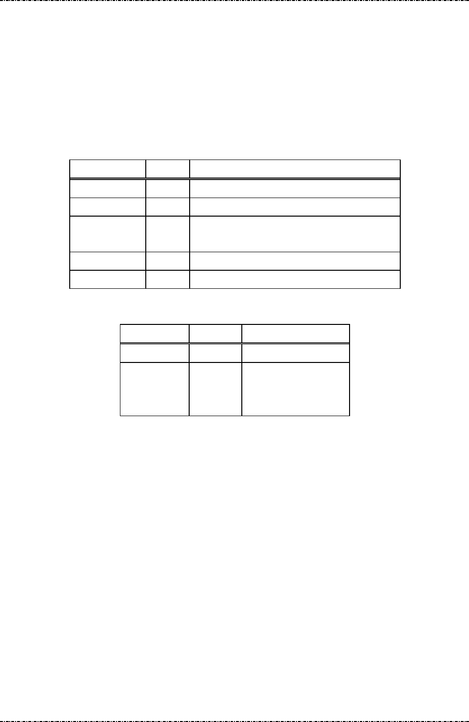
PIN Pad 791 Programmer’s Manual (PCI POS-A) UDN PM0103-U Rev. 06
Section 10 – Online transaction messages with DUKPT 2015-04-20
Page253
Uniform Industrial Corp. Proprietary and Confidential Total 342 pages
Message 7A KSN output format
Format: <STX>7A[KSN_format] <ETX>[LRC]
Message length: Fixed 6 bytes.
Usage: This message will set the key serial number (KSN) format of message 71 (DUKPT
frame). Format 0 is the original mode (strip leading ‘F’ of KSN) which is compatible of
PP690, PP790SE and PP791, Format 1 is full mode (output full 20 characters of KSN).
Message element:
Field Length
Value and description
<STX> 1 <02>
7A 2 Message ID
[KSN_format] 1 ‘0’: message 71 output KSN without leading ‘F’
‘1’: message 71 output KSN with leading ‘F’.
<ETX> 1 <03>
[LRC] 1 Checksum
Message flow:
HOST Direction PIN pad
Message 7A
<ACK> (Good LRC)
<NAK> (Bad LRC)
<EOT> (after 3 NAKs)

PIN Pad 791 Programmer’s Manual (PCI POS-A) UDN PM0103-U Rev. 06
Section 10 – Online transaction messages with DUKPT 2015-04-20
Page254
Uniform Industrial Corp. Proprietary and Confidential Total 342 pages
Message 90 Load First Initial Key Request
Format: <STX>90[IPEK][KSN]<ETX>[LRC] (Clear Text)
<STX>90[TR-31 Key Block]<ETX>[LRC] (Encrypted)
Message length: Fixed 41 or 57 bytes for clear text format, 93 or 109 bytes for TR-31 format.
Usage: Load first set of DUKPT initial key and serial number key to PP791. Consequent keys
will be generated using provided data.
If 32-characters (double length) initial key being loaded, PP791 will do key generation,
PIN entry, and other DUKPT operations in TDES manner.
PP791 implements multiple security measures to conform Payment Card Industry (PCI)
security requirement. In order to load clear text IPEK key, two authorized people with
their password are required. Otherwise the user must issue message 90 with
encrypted key value (ANSI TR31 format). See “Symmetric Keys Loading
Authentication” for detailed information.
Note: VISA required key serial number format are as follows:
4’F’ characters, a 6-digit keyset identifier, 5-digit device ID, followed by a ‘0’,
i.e. “FF FF kk kk kk dd dd d0 00 00”
Message element:
(Clear text format)
Field Length
Value and description
<STX> 1 <02>
90 2 Message ID
[IPEK] 16 or
32
Initial PIN encryption key.
32-characters Initial key will make
PP791 act in TDES DUKPT mode.
Format: hexadecimal string.
[KSN] 20 Key serial number used in generating
consequent keys.
Format: hexadecimal string.
<ETX> 1 <03>
[LRC] 1 Checksum

PIN Pad 791 Programmer’s Manual (PCI POS-A) UDN PM0103-U Rev. 06
Section 10 – Online transaction messages with DUKPT 2015-04-20
Page255
Uniform Industrial Corp. Proprietary and Confidential Total 342 pages
(Encrypted format)
Field Length
Value and description
<STX> 1 <02>
90 2 Message ID
[TR-31 Key
Block]
88 or
104
TR-31 key block with optional header
block that contains KSN.
See Appendix A for detail.
<ETX> 1 <03>
[LRC] 1 Checksum
Message flow:
HOST Direction PIN pad
Message 90
<ACK> (Good LRC)
<NAK> (Bad LRC)
<EOT> (after 3 NAKs)
Message 91
<ACK>/<NAK>/<EOT>
Example:
Clear Text
IPEK key to be loaded: ABCDEF0123456789FEDCBA9876543210
KSN: FFFF9876543210E00000
The resulting 90 message :
<STX>90ABCDEF0123456789FEDCBA9876543210FFFF9876543210E00000<ETX>[LRC]
TR-31 Key Block
Key Block Protecting Key: AA55AA55AA55AA55 3434343434343434
IPEK key to be loaded: ABCDEF0123456789 FEDCBA9876543210
KSN: FFFF9876543210E00000
Key Block Header: B0104B1TX00N0100 KS18FFFF9876543210E00000
Padded IPEK: 0080 ABCDEF0123456789 FEDCBA9876543210 30111D18CC4C
Derived KBEK: 3C50E1B7962F2171DC8643F1D923ABF7
Derived KBMK: 46FBEEB64EAE26A650952DA4F6DD8325
CMAC of (KBH + Padded key data), using KBMK: 93C3D5EBC6C407E4
Use CMAC as IV to do TDES CBC encryption on padded key data, using KBEK:
Encrypted key data: EC86E6E3B24544F97C629FB0E0586A0285D35BA78E9B13FB
Result: <02>90B0104B1TX00N0100KS18FFFF9876543210E00000EC86E6E3B24544F9
7C629FB0E0586A0285D35BA78E9B13FB93C3D5EBC6C407E4<03>
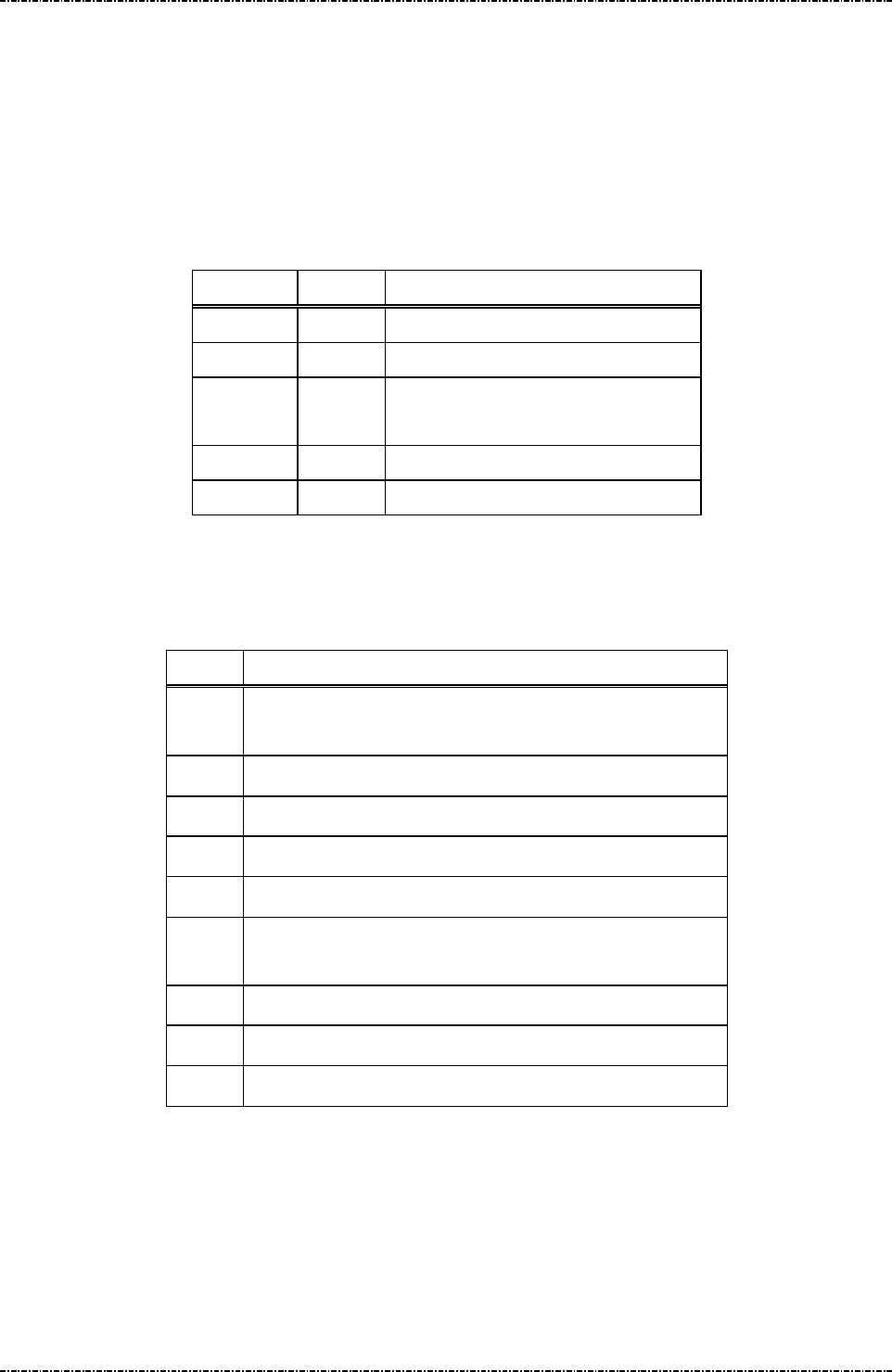
PIN Pad 791 Programmer’s Manual (PCI POS-A) UDN PM0103-U Rev. 06
Section 10 – Online transaction messages with DUKPT 2015-04-20
Page256
Uniform Industrial Corp. Proprietary and Confidential Total 342 pages
Message 91 Load Initial Key Response
Format: <STX>91[Status]<ETX>[LRC]
Message length: Variable (max 7 bytes.)
Usage: Confirmation of the initial key loading. PP791 will also show a message “IPEK n
loaded” (n = 1 or 2) to confirm the success loading of initial key of set 1 and set 2
visually.
Message element:
Field Length
Value and description
<STX> 1 <02>
91 2 Message ID
[Status] 1..2 ‘0’ if successful
‘1’ + [Error Code] if process failed.
<ETX> 1 <03>
[LRC] 1 Checksum
Message flow: Please reference message90.
Error codes:
Code Meaning
'1' Processing message 90 without authentication, process
authentication at first
'2' IPEK and KSN format error: not hexadecimal character.
'3' Internal memory allocation error.
'4' Internal fail to read key structure
‘A’ TR31 format error.
‘B’ Insecure key inject. (New key is longer than the key used to
protect it.)
‘C’ Fail to verify MAC value.
‘D’ KLK does not exist.
‘F’ Key loading count over limit.
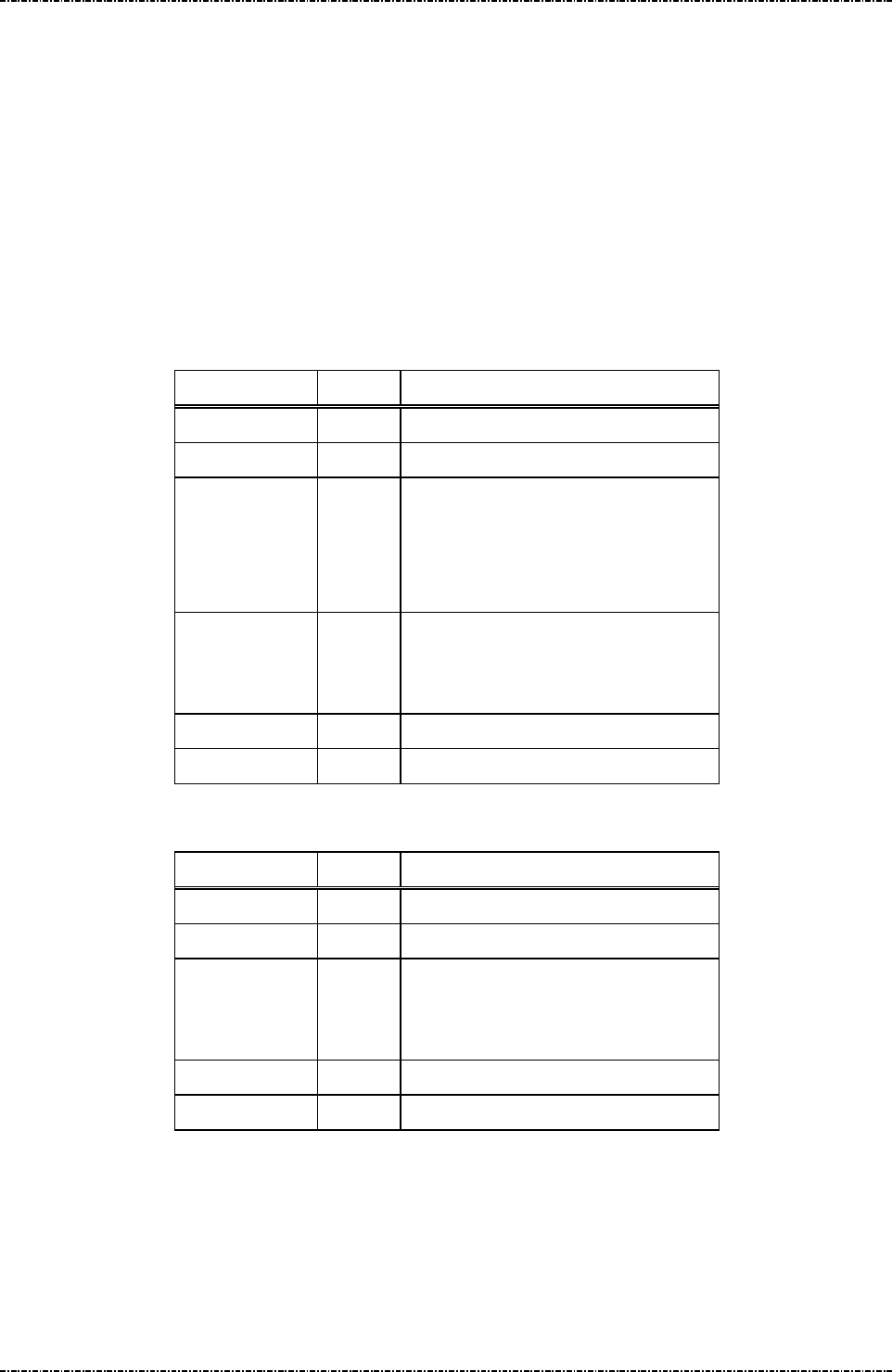
PIN Pad 791 Programmer’s Manual (PCI POS-A) UDN PM0103-U Rev. 06
Section 10 – Online transaction messages with DUKPT 2015-04-20
Page257
Uniform Industrial Corp. Proprietary and Confidential Total 342 pages
Message 94 Load Second Initial Key Request
Format: <STX>94[IPEK][KSN]<ETX>[LRC]
<STX>90[TR-31 Key Block]<ETX>[LRC] (Encrypted)
Message length: Fixed 41 or 57 bytes for clear text format, 93 or 109 bytes for TR-31 format.
Usage: Load second set of DUKPT initial key and serial number key to PP791. Consequent
keys will be generated using provided data.
Note: Refer to message 90.
Message element:
(Clear Text Format)
Field Length
Value and description
<STX> 1 <02>
94 2 Message ID
[IPEK] 16 or
32
Initial PIN encryption key.
32-characters Initial key will make
PP791 act in TDES DUKPT mode.
Format: hexadecimal string.
[KSN] 20 Key serial number used in generating
consequent keys.
Format: hexadecimal string.
<ETX> 1 <03>
[LRC] 1 Checksum
(Encrypted format)
Field Length
Value and description
<STX> 1 <02>
94 2 Message ID
[TR-31 Key
Block]
88 or
104
TR-31 key block with optional header
block that contains KSN.
See Appendix A for detail.
<ETX> 1 <03>
[LRC] 1 Checksum

PIN Pad 791 Programmer’s Manual (PCI POS-A) UDN PM0103-U Rev. 06
Section 10 – Online transaction messages with DUKPT 2015-04-20
Page258
Uniform Industrial Corp. Proprietary and Confidential Total 342 pages
Message flow:
HOST Direction PIN Pad
Message 94
<ACK> (Good LRC)
<NAK> (Bad LRC)
<EOT> (after 3 NAKs)
Message 91
<ACK>/<NAK>/<EOT>

PIN Pad 791 Programmer’s Manual (PCI POS-A) UDN PM0103-U Rev. 06
Section 10 – Online transaction messages with DUKPT 2015-04-20
Page259
Uniform Industrial Corp. Proprietary and Confidential Total 342 pages
Message 96 Select Active Key Set
Format: <STX>96[keyset]<ETX>[LRC]
Message length: Fixed 6 bytes.
Usage: Select active key set for following transactions. This parameter willl be saved and lasts
until next 96 message or DUKPT life cycle ends.
Message element:
Request frame (HOST to PIN Pad)
Field Length
Value and description
<STX> 1 <02>
96 2 Message ID
[keyset] 1 ASCII character
‘0’ = First key set
‘1’ = Second key set
<ETX> 1 <03>
[LRC] 1 Checksum
Message flow:
HOST Direction PIN Pad
Message 96
request frame
<ACK>/<NAK>/<EOT>

PIN Pad 791 Programmer’s Manual (PCI POS-A) UDN PM0103-U Rev. 06
Section 11 – ICC / SAM / Magnetic stripe card manipulating messages 2015-04-20
Page260
Uniform Industrial Corp. Proprietary and Confidential Total 342 pages
Section 11 ICC / SAM / Magnetic stripe card manipulating
messages
The following messages are used in manipulating the integrated ICC slot, SAM slot, magnetic card
reader UIC contact-less module on the PIN pad unit.
NOTE: By default, MSR function is turned off until user issue Q4 command to enable.
I00 Query Primary Smart Card Presence
I01 Primary Smart Card Cold Reset
I02 Primary Smart Card ATR Response
I04 Primary Smart Card Deactivate
I06 Primary Smart Card C-APDU
I07 Primary Smart Card R-APDU
I0F Error code message response
I11 SAM slot Cold Reset
I12 SAM slot ATR Response
I14 SAM slot Card Deactivate
I15 Select SAM Interface
I16 SAM slot C-APDU
I17 SAM slot R-APDU
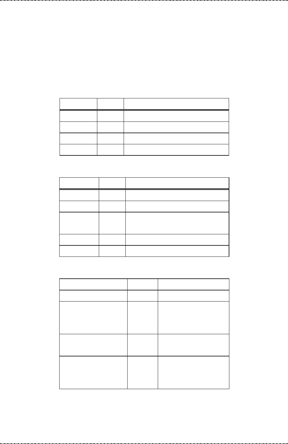
PIN Pad 791 Programmer’s Manual (PCI POS-A) UDN PM0103-U Rev. 06
Section 11 – ICC / SAM / Magnetic stripe card manipulating messages 2015-04-20
Page261
Uniform Industrial Corp. Proprietary and Confidential Total 342 pages
Message I00 Query Primary Smart Card Presence
Format: <STX>I00<ETX>[LRC] (request)
<STX>I00[response]<ETX>[LRC] (response)
Message length: Fixed 6 bytes (request frame) / 7 bytes (response frame).
Usage: Upon receiving a query card packet, PP791 checks whether the card is present in the
primary card reader or not. If the card exists in the reader, PP791 replies the code ‘F’.
Otherwise, the code ‘0’ is used instead.
Request frame (HOST to PP791)
Field Length
Value and description
<STX> 1 <02>
I00 3 Message ID
<ETX> 1 <03>
[LRC] 1 Checksum
Response frame (PP791 to HOST)
Field Length
Value and description
<STX> 1 <02>
I00 3 Message ID
[Response] 1 0: Smart card not exists.
F: Smart card exists
<ETX> 1 <03>
[LRC] 1 Checksum
Message flow:
HOST Direction
PP791
Message I00 (Request)
<ACK> (Good LRC)
<NAK> (Bad LRC)
<EOT> (after 3 NAKs)
Check card existence
Message I00 (response)
<ACK> (Good echo)
<NAK> (Bad LRC)
<EOT> (after 3 NAKs)

PIN Pad 791 Programmer’s Manual (PCI POS-A) UDN PM0103-U Rev. 06
Section 11 – ICC / SAM / Magnetic stripe card manipulating messages 2015-04-20
Page262
Uniform Industrial Corp. Proprietary and Confidential Total 342 pages
Message I01 Primary Smart Card Cold Reset
Format: <STX>I01<ETX>[LRC]
Message length: Fixed 6 bytes.
Usage: PP791 performs a cold reset on the active smart card. If the operation is successful,
PP791 sends the message I02 with the “Answer to Reset” (ATR) of the smart card to
host. Otherwise, the message I0F bears the error code is to be sent back.
Message element:
Field Length
Value and description
<STX> 1 <02>
I01 3 Message ID
<ETX> 1 <03>
[LRC] 1 Checksum
Message flow:
HOST Direction PP791
Message I01
<ACK> (Good LRC)
<NAK> (Bad LRC)
<EOT> (after 3 NAKs)
Smart card cold reset.
Message I02 (ATR)
<ACK> (Good LRC)
<NAK> (Bad LRC)
<EOT> (after 3 NAKs)

PIN Pad 791 Programmer’s Manual (PCI POS-A) UDN PM0103-U Rev. 06
Section 11 – ICC / SAM / Magnetic stripe card manipulating messages 2015-04-20
Page263
Uniform Industrial Corp. Proprietary and Confidential Total 342 pages
Message I02 Primary Smart Card ATR Response
Format: <STX>I02[ATR]<ETX>[LRC]
Message length: Variable, depending on the specification of smart card..
Usage: The message contains the “Answer to Reset” (ATR) of the smart card to be sent to
host. In general, the ATR conforms to the ISO 7816-3 or EMV 4.3 Book 1. See these
standards for more detail information.
Message element:
Field Length
Value and description
<STX> 1 <02>
I02 3 Message ID
[ATR] N Answer to reset data.
Format: Hexadecimal string.
<ETX> 1 <03>
[LRC] 1 Checksum
Message flow: Please refer to message I01.

PIN Pad 791 Programmer’s Manual (PCI POS-A) UDN PM0103-U Rev. 06
Section 11 – ICC / SAM / Magnetic stripe card manipulating messages 2015-04-20
Page264
Uniform Industrial Corp. Proprietary and Confidential Total 342 pages
Message I04 Primary Smart Card Deactivate
Format: <STX>I04<ETX>[LRC]
Message length: Fixed 6 bytes.
Usage: Upon receiving the card deactivate packet, PP791 sets the active smart card to the
deactivate state. If the operation is successful, PP791 replies same packet to confirm.
Otherwise, message I0F with the error code is used instead..
Message element:
Field Length
Value and description
<STX> 1 <02>
I04 3 Message ID
<ETX> 1 <03>
[LRC] 1 Checksum
Message flow:
HOST Direction PP791
Message I04
<ACK> (Good LRC)
<NAK> (Bad LRC)
<EOT> (after 3 NAKs)
Deactivate smart card.
Message I04 (success)
Message I0F (fail)
<ACK> (Good LRC)
<NAK> (Bad LRC)
<EOT> (after 3 NAKs)
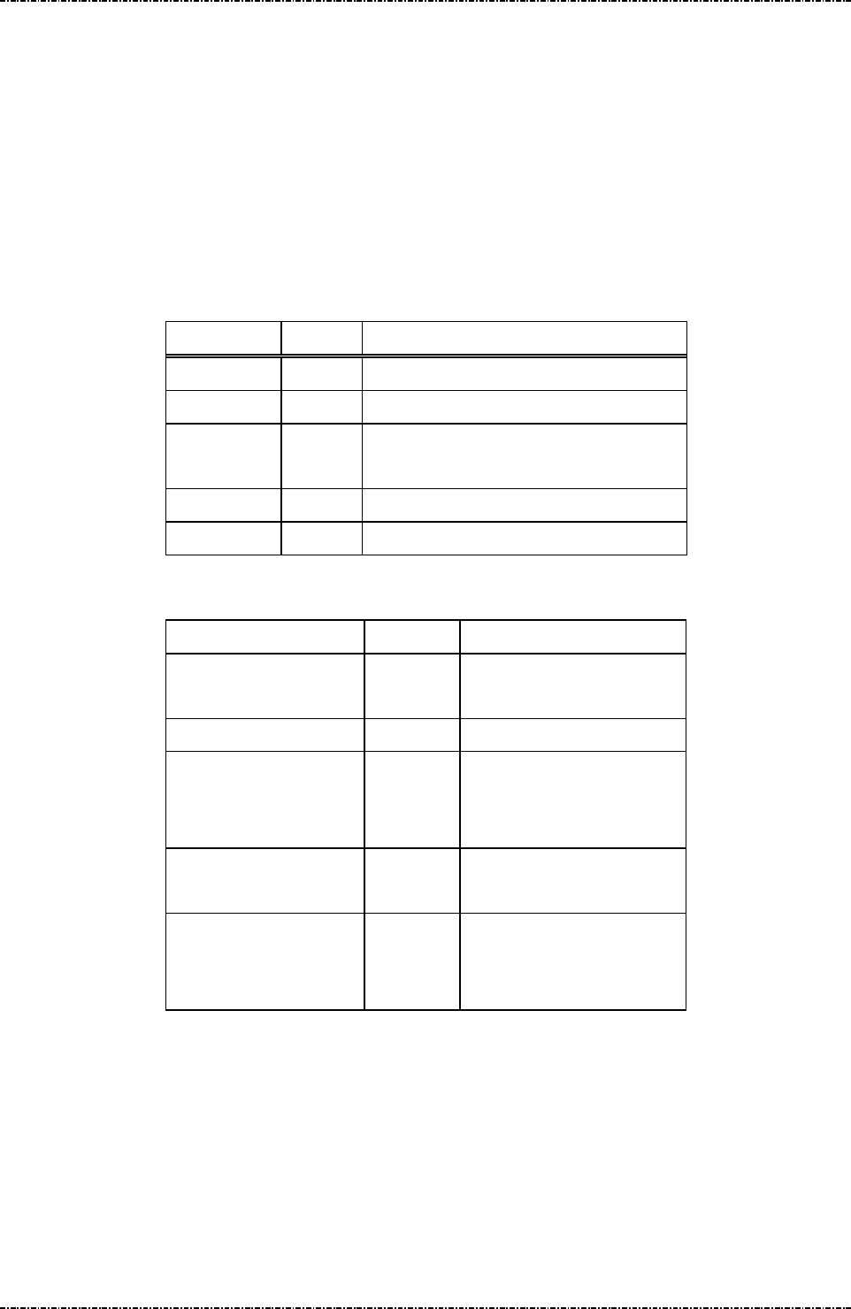
PIN Pad 791 Programmer’s Manual (PCI POS-A) UDN PM0103-U Rev. 06
Section 11 – ICC / SAM / Magnetic stripe card manipulating messages 2015-04-20
Page265
Uniform Industrial Corp. Proprietary and Confidential Total 342 pages
Message I06 Primary Smart Card C-APDU
Format: <STX>I06[C-APDU]<ETX>[LRC]
Message length: Variable 14 to 530 bytes.
Usage: The Command APDU (application protocol data unit) is the data to be sent to the
active smart card. PP791 's smart card reader will handle base protocols such as T=0
and T=1, so programmer need only send APDU. In general, PP791 will reply the
message I07 (response APDU from card) to host in 1 second. For any error, PP791
will send message I0F with error code back.
Message element:
Field Length
Value and description
<STX> 1 <02>
I06 3 Message ID
[C-APDU] 8..524 Smart card command APDU.
Format: hexadecimal string.
<ETX> 1 <03>
[LRC] 1 Checksum
Message flow:
HOST Direction PP791
Message I01 (Smart card power on and
ATR response)
Message I06
<ACK> (Good LRC)
<NAK> (Bad LRC)
<EOT> (after 3 NAKs)
Communication with card.
Message I07 or I0F
<ACK> (Good LRC)
<NAK> (Bad LRC)
<EOT> (after 3 NAKs)

PIN Pad 791 Programmer’s Manual (PCI POS-A) UDN PM0103-U Rev. 06
Section 11 – ICC / SAM / Magnetic stripe card manipulating messages 2015-04-20
Page266
Uniform Industrial Corp. Proprietary and Confidential Total 342 pages
Message I07 Primary Smart Card R-APDU
Format: <STX>I07[R-APDU]<ETX>[LRC]
Message length: Variable 10 to 530 bytes.
Usage: After smart card processes the Command-APDU, it puts the result as the
Response-APDU. PP791 packs the Response-APDU into this message packet and
sends to host.
Message element:
Field Length
Value and description
<STX> 1 <02>
I07 3 Message ID
[R-APDU] 4.. 524
Smart card response APDU
Format: hexadecimal string.
<ETX> 1 <03>
[LRC] 1 Checksum
Message flow: Please refer to message I06.

PIN Pad 791 Programmer’s Manual (PCI POS-A) UDN PM0103-U Rev. 06
Section 11 – ICC / SAM / Magnetic stripe card manipulating messages 2015-04-20
Page267
Uniform Industrial Corp. Proprietary and Confidential Total 342 pages
Message I08 Smart Card Offline PIN Verification (EMV)
Format: <STX>I08[Mode]<FS>[Prompt & Amount]<ETX>[LRC] (Clear-text mode)
<STX>I08[Mode]<FS>[Prompt & Amount]<FS>RSA public Exp]<FS>[RSA
public Modulus]<ETX>[LRC] (Cipher-text mode)
Message length: Variable.
Usage: User could apply message I01 ~ I06 to implement his EMV transaction flow. In EMV
transaction flow, user could apply this message to implement the offline PIN
verification operation defined by EMV Co. User applies this message to make PIN pad
ask cardholder enter his PIN on PIN pad and then PIN pad will send the PIN block (in
clear -text or cipher-text) to IC card. For secure consideration, user will not get any
information about cardholder’s PIN, user can only get the PIN verification result from
PIN pad.
In PIN verification operation, PIN pad will issue “Get Challenge” command to get
random number from smart card for PIN encryption.
Message element:
Field Length
Value and description
<STX> 1 <02>
I08 3 Message ID
[Mode] 1 0: Clear PIN mode
1: Cipher PIN mode
<FS> 1 <1C>
[Prompt & Amount] var ASCII string. The data in this filed is used to
present to cardholder. The length of this filed could
be 1 ~ 32. Ex. Amount: 12.345
PIN pad will append messages on line 3 and 4 to
inform user to make a confirmation.
<FS> 1 <1C> (Optional, if Mode is 1)
[RSA public Exp] 1 (Optional, if Mode is 1)
1: 3
2: 2^16 + 1
<FS> 1 (Optional, if Mode is 1)
<1C>
[RSA public Modulus] Var. Hex string. RSA modulus. (Optional, if Mode is 1)
<ETX> 1 <03>
[LRC] 1 Checksum

PIN Pad 791 Programmer’s Manual (PCI POS-A) UDN PM0103-U Rev. 06
Section 11 – ICC / SAM / Magnetic stripe card manipulating messages 2015-04-20
Page268
Uniform Industrial Corp. Proprietary and Confidential Total 342 pages
Message flow:
HOST Direction PP791
Message I08
<ACK> (Good LRC)
<NAK> (Bad LRC)
<EOT> (after 3 NAKs)
Communication with card.
Message I09 or I0F
<ACK> (Good LRC)
<NAK> (Bad LRC)
<EOT> (after 3 NAKs)

PIN Pad 791 Programmer’s Manual (PCI POS-A) UDN PM0103-U Rev. 06
Section 11 – ICC / SAM / Magnetic stripe card manipulating messages 2015-04-20
Page269
Uniform Industrial Corp. Proprietary and Confidential Total 342 pages
Message I09 Response of Smart Card Offline PIN Verification (EMV)
Format: <STX>I09[Response]<ETX>[LRC]
Message length: Fixed 7 bytes.
Usage: PIN pad will return the result of PIN verification operation. For EMV rule, it’s
recommended that terminal applies next CVM if get response equal to ‘C’, ‘E’, and ‘S’,
terminates EMV transaction if get response equal to ‘D’ and ‘F’.
Message element:
Field Length
Value and description
<STX> 1 <02>
I09 3 Message ID
[Response] 1 ASCII character.
A: PIN is verified successfully.
C: Cardholder bypass PIN.
D: Communication failed (with smart card).
E: Exceed PIN try limit
S: No random number from
smart card.
F: Other errors
<ETX> 1 <03>
[LRC] 1 Checksum
Message flow: Please refer to message I08.

PIN Pad 791 Programmer’s Manual (PCI POS-A) UDN PM0103-U Rev. 06
Section 11 – ICC / SAM / Magnetic stripe card manipulating messages 2015-04-20
Page270
Uniform Industrial Corp. Proprietary and Confidential Total 342 pages
Message I0F Error Codes
Format: <STX>I0F[error code]<ETX>[LRC]
Message length: Fixed 8 bytes.
Usage: This message contains the error codes to indicate what’s going on for error situation.
The error code list is as follows:
"01" - ATR error or NO smart card.
"02" - APDU data length is not enough.
"03" – ICC/SAM card not powered yet, use I01 first.
"04" - The alphanumeric in APDU data are out of range.
"05" - Current smart card reader doesn't have card in.
"06" - Smart card interface switch failed.
"07" - PP791 Smart card module timed out.
"08" - Smart card APDU command failed.
”09” - This parameter does not supported by PP791.
”0A” - This unit does not have corresponding peripheral (ICC reader or SAM).
”0B” – Already power up.
Message element:
Field Length
Value and description
<STX> 1 <02>
I0F 3 Message ID
[Error code]
2 Error codes.
<ETX> 1 <03>
[LRC] 1 Checksum
Message flow: Please refer to I00 to I07.

PIN Pad 791 Programmer’s Manual (PCI POS-A) UDN PM0103-U Rev. 06
Section 11 – ICC / SAM / Magnetic stripe card manipulating messages 2015-04-20
Page271
Uniform Industrial Corp. Proprietary and Confidential Total 342 pages
Message I11 SAM slot Cold Reset
Format: <STX>I11<ETX>[LRC]
Message length: Fixed 6 bytes.
Usage: PP791 performs a cold reset on the active SAM interface. If the operation is
succeeded, PP791 sends the message I12 with the “Answer to Reset” (ATR) of the
smart card to host. Otherwise, the message I0F bears the error code is to be sent
back.
Message element:
Field Length
Value and description
<STX> 1 <02>
I11 3 Message ID
<ETX> 1 <03>
[LRC] 1 Checksum
Message flow:
HOST Direction PP791
Message I15 (Select interface and
response)
Message I11
<ACK> (Good LRC)
<NAK> (Bad LRC)
<EOT> (after 3 NAKs)
Smart card cold reset.
Message I12 (ATR)
<ACK> (Good LRC)
<NAK> (Bad LRC)
<EOT> (after 3 NAKs)

PIN Pad 791 Programmer’s Manual (PCI POS-A) UDN PM0103-U Rev. 06
Section 11 – ICC / SAM / Magnetic stripe card manipulating messages 2015-04-20
Page272
Uniform Industrial Corp. Proprietary and Confidential Total 342 pages
Message I12 SAM slot ATR Response
Format: <STX>I12[ATR]<ETX>[LRC]
Message length: Variable, depending on the specification of smart card..
Usage: The message contains the “Answer to Reset” (ATR) of the SAM card to be sent to host.
In general, the ATR conforms to the ISO 7816-3 or EMV 2000 level 1. See these
standards for more detail information..
Message element:
Field Length
Value and description
<STX> 1 <02>
I12 3 Message ID
[ATR] N Answer to reset data.
Format: Hexadecimal string.
<ETX> 1 <03>
[LRC] 1 Checksum
Message flow: Please refer to message I11.

PIN Pad 791 Programmer’s Manual (PCI POS-A) UDN PM0103-U Rev. 06
Section 11 – ICC / SAM / Magnetic stripe card manipulating messages 2015-04-20
Page273
Uniform Industrial Corp. Proprietary and Confidential Total 342 pages
Message I14 SAM slot Card Deactivate
Format: <STX>I14<ETX>[LRC]
Message length: Fixed 6 bytes.
Usage: Upon receiving the card deactivate packet, PP791 sets the active smart card to the
deactivate state. If the operation is successful, PP791 replies same packet to confirm.
Otherwise, message I0F with the error code is used instead.
Message element:
Field Length
Value and description
<STX> 1 <02>
I14 3 Message ID
<ETX> 1 <03>
[LRC] 1 Checksum
Message flow:
HOST Direction PP791
Message I14
<ACK> (Good LRC)
<NAK> (Bad LRC)
<EOT> (after 3 NAKs)
Deactivate smart card.
Message I14 (success)
Message I0F (fail)
<ACK> (Good LRC)
<NAK> (Bad LRC)
<EOT> (after 3 NAKs)
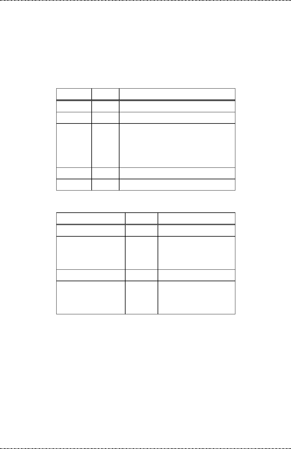
PIN Pad 791 Programmer’s Manual (PCI POS-A) UDN PM0103-U Rev. 06
Section 11 – ICC / SAM / Magnetic stripe card manipulating messages 2015-04-20
Page274
Uniform Industrial Corp. Proprietary and Confidential Total 342 pages
Message I15 SAM Select Interface
Format: <STX>I15[IF_code]<ETX>[LRC]
Message length: Fixed 7 bytes.
Usage: PP791 sets the active interface of the smart card reader. If operation succeeds, PP791
replies with the same packet to confirm. Otherwise, message I0F with error code is
used instead. All SAM slot commands will be sent to the card via the active interface.
Message element:
Field Length
Value and description
<STX> 1 <02>
I15 3 Message ID
[IF_code]
1 Interface code.
‘1’ = SAM 1
'2' = SAM 2
'3' = SAM 3
<ETX> 1 <03>
[LRC] 1 Checksum
Message flow:
HOST Direction PP791
Message I15
<ACK> (Good LRC)
<NAK> (Bad LRC)
<EOT> (after 3 NAKs)
Message I15
<ACK> (Good LRC)
<NAK> (Bad LRC)
<EOT> (after 3 NAKs)
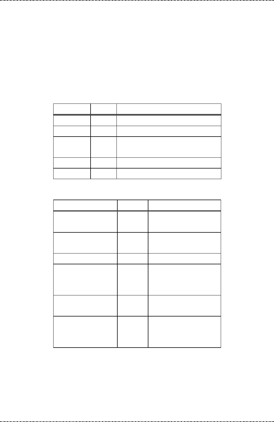
PIN Pad 791 Programmer’s Manual (PCI POS-A) UDN PM0103-U Rev. 06
Section 11 – ICC / SAM / Magnetic stripe card manipulating messages 2015-04-20
Page275
Uniform Industrial Corp. Proprietary and Confidential Total 342 pages
Message I16 SAM slot C-APDU
Format: <STX>I16[C-APDU]<ETX>[LRC]
Message length: Variable 14 to 530 bytes.
Usage: The Command APDU (application protocol data unit) is the data to be sent to the
active smart card. PP791 's SAM reader will handle base protocols such as T=0 and
T=1, so programmer need only send APDU. In general, PP791 will reply the message
I17 (response APDU from card) to host in 1 second. For any error, PP791 will send
message I0F with error code back.
Message element:
Field Length
Value and description
<STX> 1 <02>
I16 3 Message ID
[C-APDU] 8..524 Smart card command APDU.
Format: hexadecimal string.
<ETX> 1 <03>
[LRC] 1 Checksum
Message flow:
HOST Direction PP791
Message I15 (Select interface and
response)
Message I11 (Smart card power on and
ATR response)
Message I16
<ACK> (Good LRC)
<NAK> (Bad LRC)
<EOT> (after 3 NAKs)
Communication with card.
Message I17 or I0F
<ACK> (Good LRC)
<NAK> (Bad LRC)
<EOT> (after 3 NAKs)

PIN Pad 791 Programmer’s Manual (PCI POS-A) UDN PM0103-U Rev. 06
Section 11 – ICC / SAM / Magnetic stripe card manipulating messages 2015-04-20
Page276
Uniform Industrial Corp. Proprietary and Confidential Total 342 pages
Message I17 SAM slot R-APDU
Format: <STX>I17[R-APDU]<ETX>[LRC]
Message length: Variable 10 to 530 bytes.
Usage: After SAM card processes the Command-APDU, it puts the result as the
Response-APDU. PP791 packs the Response-APDU into this message packet and
sends to host.
Message element:
Field Length
Value and description
<STX> 1 <02>
I17 3 Message ID
[R-APDU] 4.. 524
Smart card response APDU
Format: hexadecimal string.
<ETX> 1 <03>
[LRC] 1 Checksum
Message flow: Please refer to message I16.
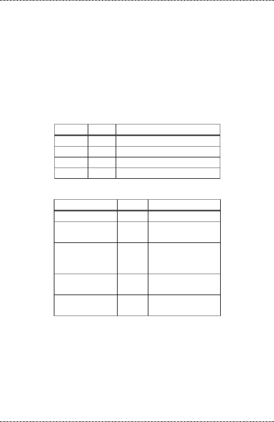
PIN Pad 791 Programmer’s Manual (PCI POS-A) UDN PM0103-U Rev. 06
Section 11 – ICC / SAM / Magnetic stripe card manipulating messages 2015-04-20
Page277
Uniform Industrial Corp. Proprietary and Confidential Total 342 pages
Message Q1 Display SWIPE CARD message
Format: <STX>Q1<ETX>[LRC]
Message length: Fixed 5 bytes.
Usage: The PIN pad will display the prompt “SWIPE CARD” on its LCD until a card is swiped
through the reader slot or Z1 message (reset state) received or CAN key pressed.
After magnetic stripe card swiped, PIN pad will collect and decode the card data, strip
start sentinel, end sentinel, and LRC character. Then send the data to the HOST and
display “PIN PAD PROCESSING” message.
NOTE: For first time use of PP791, issue Q4 message to enable MSR tracks before
issuing Q1.
Message element:
Field Length Value and description
<STX> 1 <02>
Q1 2 Message ID
<ETX> 1 <03>
[LRC] 1 Checksum
Message flow:
HOST Direction PIN pad
Message Q1
“SWIPE CARD” displayed
on LCD
<ACK> (Good LRC)
<NAK> (Bad LRC)
<EOT> (after 3 NAKs)
(User swipe magnetic card)
Message 81
<ACK> (Good LRC)
<NAK> (Bad LRC)

PIN Pad 791 Programmer’s Manual (PCI POS-A) UDN PM0103-U Rev. 06
Section 11 – ICC / SAM / Magnetic stripe card manipulating messages 2015-04-20
Page278
Uniform Industrial Corp. Proprietary and Confidential Total 342 pages
Message Q2Transaction Completed
Format: <STX>Q2<ETX>[LRC]
Message length: Fixed 5 bytes.
Usage: Indicate that a transaction is now completed. The PIN pad will display a “Thank You”
message for three seconds and then goes to IDLE state.
Note: This message can also be used on PIN transaction (70, Z60, Z62)
Message element:
Field Length Value and description
<STX>
1 <02>
Q2 2 Message ID
<ETX>
1 <03>
[LRC] 1 Checksum
Message flow:
HOST Direction PIN pad
Message Q2
<ACK> (Good LRC)
<NAK> (Bad LRC)
<EOT> (after 3 NAKs)
Display “Thank You”
for 3 seconds, followed
by idle prompt.

PIN Pad 791 Programmer’s Manual (PCI POS-A) UDN PM0103-U Rev. 06
Section 11 – ICC / SAM / Magnetic stripe card manipulating messages 2015-04-20
Page279
Uniform Industrial Corp. Proprietary and Confidential Total 342 pages
Message Q3Ignore Card Swipe
Format: <STX>Q3<ETX>[LRC]
Message length: Fixed 5 bytes.
Usage: The HOST should send a message Q3 after receiving card data and decide not to
accept another card temporarily. Upon receiving this message, the PIN pad will display
“PIN PAD PROCESSING” prompts and ignore any card swiping.
Message element:
Field Length
Value and description
<STX> 1 <02>
Q3 2 Message ID
<ETX> 1 <03>
[LRC] 1 Checksum
Message flow:
HOST Direction PIN pad
Message Q3
<ACK> (Good LRC)
<NAK> (Bad LRC)
<EOT> (after 3 NAKs)
“PIN PAD PROCESSING”
displayed on LCD
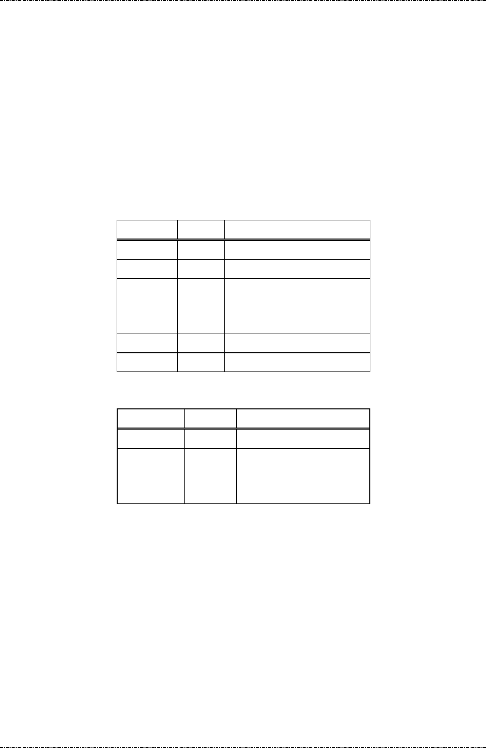
PIN Pad 791 Programmer’s Manual (PCI POS-A) UDN PM0103-U Rev. 06
Section 11 – ICC / SAM / Magnetic stripe card manipulating messages 2015-04-20
Page280
Uniform Industrial Corp. Proprietary and Confidential Total 342 pages
Message Q4 Enable/Disable Magnetic Card Reader
Format: <STX>Q4[flag]<ETX>[LRC]
Message length: Fixed 6 bytes.
Usage: All the tracks are disabled by default (After each re-power on PIN pad). The HOST can
use this message to have PIN pad enable or disable the magnetic card reader. Only
track 2 is enabled if [flag] field contains ‘0’. All tracks will be enabled if [flag] field
contains a ‘2’.
NOTE: Please refer to message 81 for returned magnetic card data format.
Message element:
Field Length
Value and description
<STX> 1 <02>
Q4 2 Message ID
[flag] 1 ‘0’: enable Track2 only
‘1’: disable
‘2’: enable all tracks of MSR
<ETX> 1 <03>
[LRC] 1 Checksum
Message flow:
HOST Direction
PIN pad
Message Q4
<ACK> (Good LRC)
<NAK> (Bad LRC)
<EOT> (after 3 NAKs)
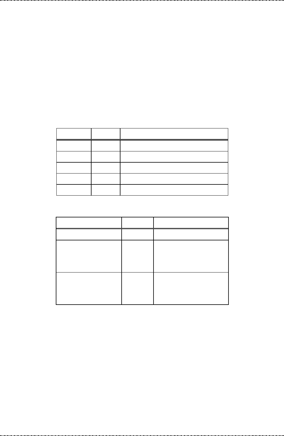
PIN Pad 791 Programmer’s Manual (PCI POS-A) UDN PM0103-U Rev. 06
Section 11 – ICC / SAM / Magnetic stripe card manipulating messages 2015-04-20
Page281
Uniform Industrial Corp. Proprietary and Confidential Total 342 pages
Message Q5Set MSR Retry Count
Format: <STX>Q5[RetryCount]<ETX>[LRC]
Message length: Fixed 6 bytes.
Usage: This command will set a retry count for the MSR swiping initiated by message Q1 and
Z90.
If PIN pad cannot decode any data from latest swipe, retry count larger than “0”, and
timeout is not reached, PIN pad will show “BAD READ” on LCD and waiting for next
swipe. Until timeout or retry counter reached maximum. This setting will be kept in
battery powered memory and effective all the time.
Message element:
Field Length Value and description
<STX> 1 <02>
Q5 2 Message ID
RetryCnt 1 ‘0’ to ‘9’, MSR retry count.
<ETX> 1 <03>
[LRC] 1 Checksum
Message flow:
HOST Direction PIN Pad
Message Q5
<ACK> (Good LRC)
<NAK> (Bad LRC)
<EOT> (after 3 NAKs)
Save the setting or display
error message when
RetryCnt out of range.
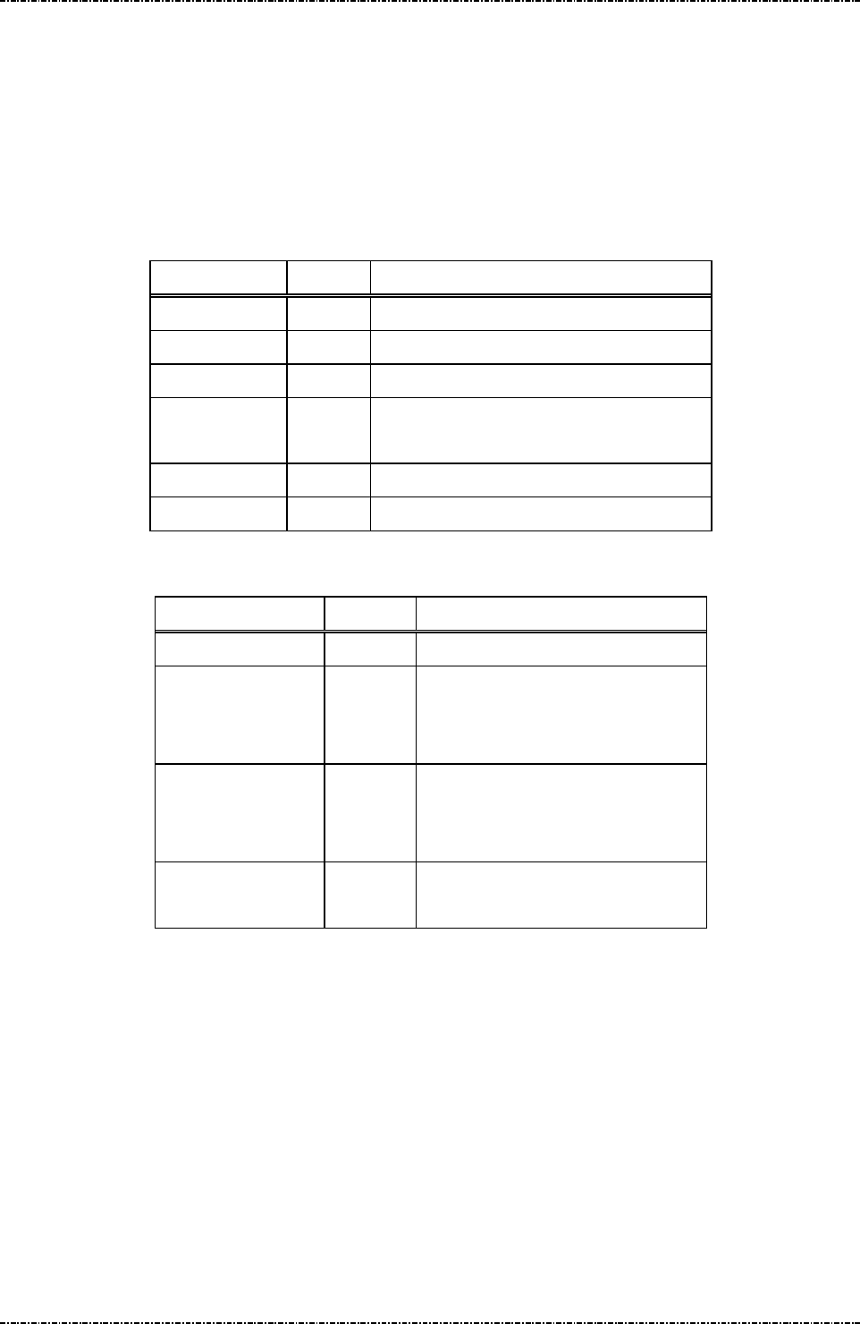
PIN Pad 791 Programmer’s Manual (PCI POS-A) UDN PM0103-U Rev. 06
Section 11 – ICC / SAM / Magnetic stripe card manipulating messages 2015-04-20
Page282
Uniform Industrial Corp. Proprietary and Confidential Total 342 pages
Message Q6 MSR Operation Control
Format: <STX>Q6.[flag]<ETX>[LRC] (request frame)
Message length: 7 bytes.
Usage: This command can be used to set MSR output format.
Message element:
Request fame (HOST to PP791)
Field Length
Value and description
<STX> 1 <02>
Q6 2 Message ID
. 1 <2E>, delimiter
[flag] 1 ‘0’: Clear-Text Card Data
‘2’: Clear-Text Card Data with Sentinels.
<ETX> 1 <03>
[LRC] 1 Checksum
Message flow:
HOST Direction
PIN pad
Message Q6
<ACK> (Good LRC)
<NAK> (Bad LRC)
<EOT> (after 3 NAKs)
Message Q6 (echo of request frame
when success) or <EOT> (when
format error.)
<ACK> / <NAK> /
<EOT>
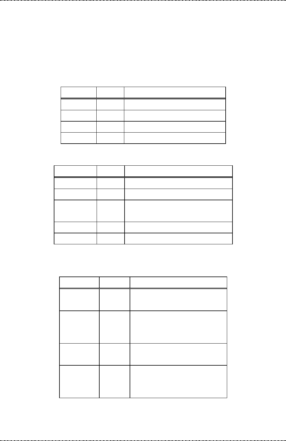
PIN Pad 791 Programmer’s Manual (PCI POS-A) UDN PM0103-U Rev. 06
Section 11 – ICC / SAM / Magnetic stripe card manipulating messages 2015-04-20
Page283
Uniform Industrial Corp. Proprietary and Confidential Total 342 pages
Message Q7MSR Mode Query
Format: <STX>Q7<ETX>[LRC] (request frame)
<STX>Q7[status]<ETX>[LRC] (response frame)
Message length: Fixed 5 bytes for request, 6 bytes for response.
Usage: This command will query MSR processing option.
Message element:
Request fame (HOST to PP791)
Field Length
Value and description
<STX> 1 <02>
Q7 2 Message ID
<ETX> 1 <03>
[LRC] 1 Checksum
Response fame (PP791 to HOST)
Field Length
Value and description
<STX> 1 <02>
Q7 2 Message ID
[status] 1 ‘0’: Clear-Text Card Data
‘2’: Clear-Text Card Data with Sentinels.
<ETX> 1 <03>
[LRC] 1 Checksum
Message flow:
HOST Direction
PIN pad
Message Q7
(request)
<ACK> (Good LRC)
<NAK> (Bad LRC)
<EOT> (after 3 NAKs)
Message Q7
(response)
<ACK> /
<NAK> /
<EOT>
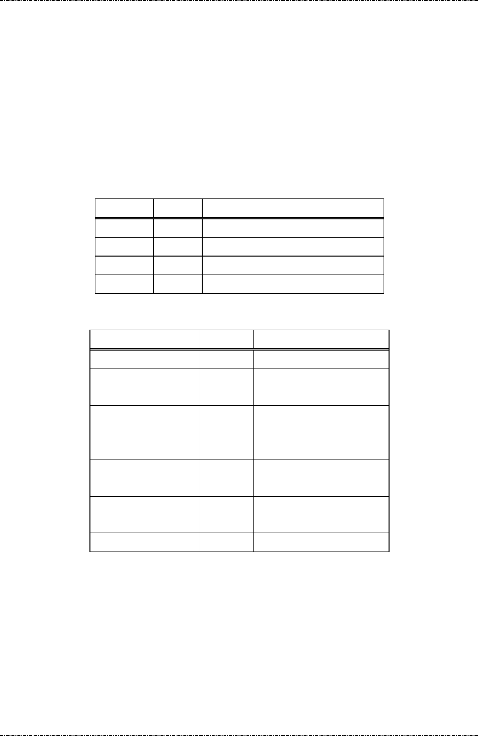
PIN Pad 791 Programmer’s Manual (PCI POS-A) UDN PM0103-U Rev. 06
Section 11 – ICC / SAM / Magnetic stripe card manipulating messages 2015-04-20
Page284
Uniform Industrial Corp. Proprietary and Confidential Total 342 pages
Message Q8Display TAP CARD message
Format: <STX>Q8<ETX>[LRC]
Message length: Fixed 5 bytes.
Usage: The PIN pad will display the prompt “TAP CARD” on its LCD until a contactless card is
taped or Z1 message (reset state) received or CAN key pressed.
After contactless card taped, PIN pad will collect card data then send the data to the
HOST.
NOTE: Before issue message Q8 to retrieve contactless card data after PIN pad
re-power on, issue QA message to enable contactless module’s tracks.
Message element:
Field Length Value and description
<STX> 1 <02>
Q8 2 Message ID
<ETX> 1 <03>
[LRC] 1 Checksum
Message flow:
HOST Direction PIN pad
Message Q8
“TAP CARD” displayed on
LCD
<ACK> (Good LRC)
<NAK> (Bad LRC)
<EOT> (after 3 NAKs)
(User taps contactless card)
Message 83
<ACK> (Good LRC)
<NAK> (Bad LRC)
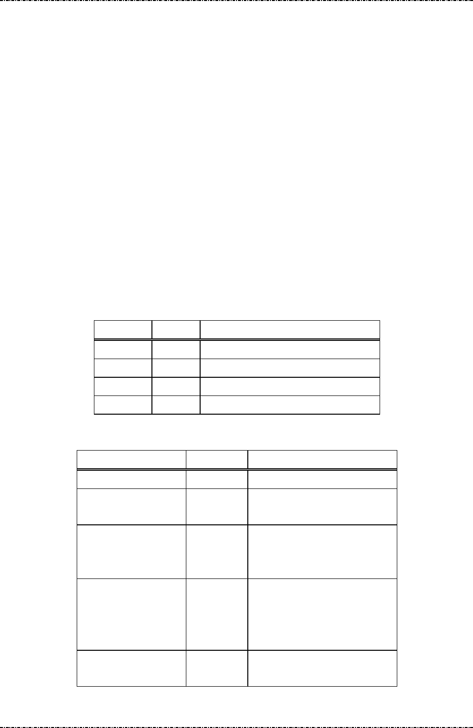
PIN Pad 791 Programmer’s Manual (PCI POS-A) UDN PM0103-U Rev. 06
Section 11 – ICC / SAM / Magnetic stripe card manipulating messages 2015-04-20
Page285
Uniform Industrial Corp. Proprietary and Confidential Total 342 pages
Message Q9Display SWIPE / TAP CARD message
Format: <STX>Q9<ETX>[LRC]
Message length: Fixed 5 bytes.
Usage: The PIN pad will display the prompt “SWIPE / TAP CARD” on its LCD until a card is
swiped or taped through the reader slot or Z1 message (reset state) received or CAN
key pressed.
After magnetic stripe card swiped, PIN pad will collect and decode the card data, strip
start sentinel, end sentinel, and LRC character. Then send the data to the HOST and
display “PIN PAD PROCESSING” message.
After contactless card taped, PIN pad will collect card data and send the data to the
HOST and display “PIN PAD PROCESSING” message.
NOTE: Before issue message Q9 to retrieve contactless / magnetic stripe card data
after PIN pad re-power on, issue Q4 and QA messages to enable contactless module’s
tracks and magnetic stripe reader tracks.
NOTE: The returned message will be with “81” or “83” according the source of card
data.
Message element:
Field Length Value and description
<STX> 1 <02>
Q9 2 Message ID
<ETX> 1 <03>
[LRC] 1 Checksum
Message flow:
HOST Direction PIN pad
Message Q9
“SWIPE/TAP CARD” displayed
on LCD
<ACK> (Good LRC)
<NAK> (Bad LRC)
<EOT> (after 3 NAKs)
(User swipe magnetic card)
Message 81
(User taps contactless card)
Message 83
<ACK> (Good LRC)
<NAK> (Bad LRC)

PIN Pad 791 Programmer’s Manual (PCI POS-A) UDN PM0103-U Rev. 06
Section 11 – ICC / SAM / Magnetic stripe card manipulating messages 2015-04-20
Page286
Uniform Industrial Corp. Proprietary and Confidential Total 342 pages
Message QA Enable/Disable Contactless Card Reader
Format: <STX>QA[flag]<ETX>[LRC]
Message length: Fixed 6 bytes.
Usage: All the tracks are disabled by default (After each re-power on PIN pad). The HOST can
use this message to have PIN pad enable or disable the contact-less card reader. Only
track 2 is enabled if [flag] field contains ‘0’. Both tracks will be enabled if [flag] field
contains a ‘2’.
NOTE: Please refer to message 83 for returned magnetic card data format.
Note. QA message will set prefix <81>, <82> and <83> as prefix of track data 1, 2 and 3.
Message element:
Field Length
Value and description
<STX> 1 <02>
QA 2 Message ID
[flag] 1 ‘0’: enable Track2 only
‘1’: disable
‘2’: enable all tracks of MSR
<ETX> 1 <03>
[LRC] 1 Checksum
Message flow:
HOST Direction PIN pad
Message QA
<ACK> (Good LRC)
<NAK> (Bad LRC)
<EOT> (after 3 NAKs)
(<EOT>Contactless card reader is initialized failed)
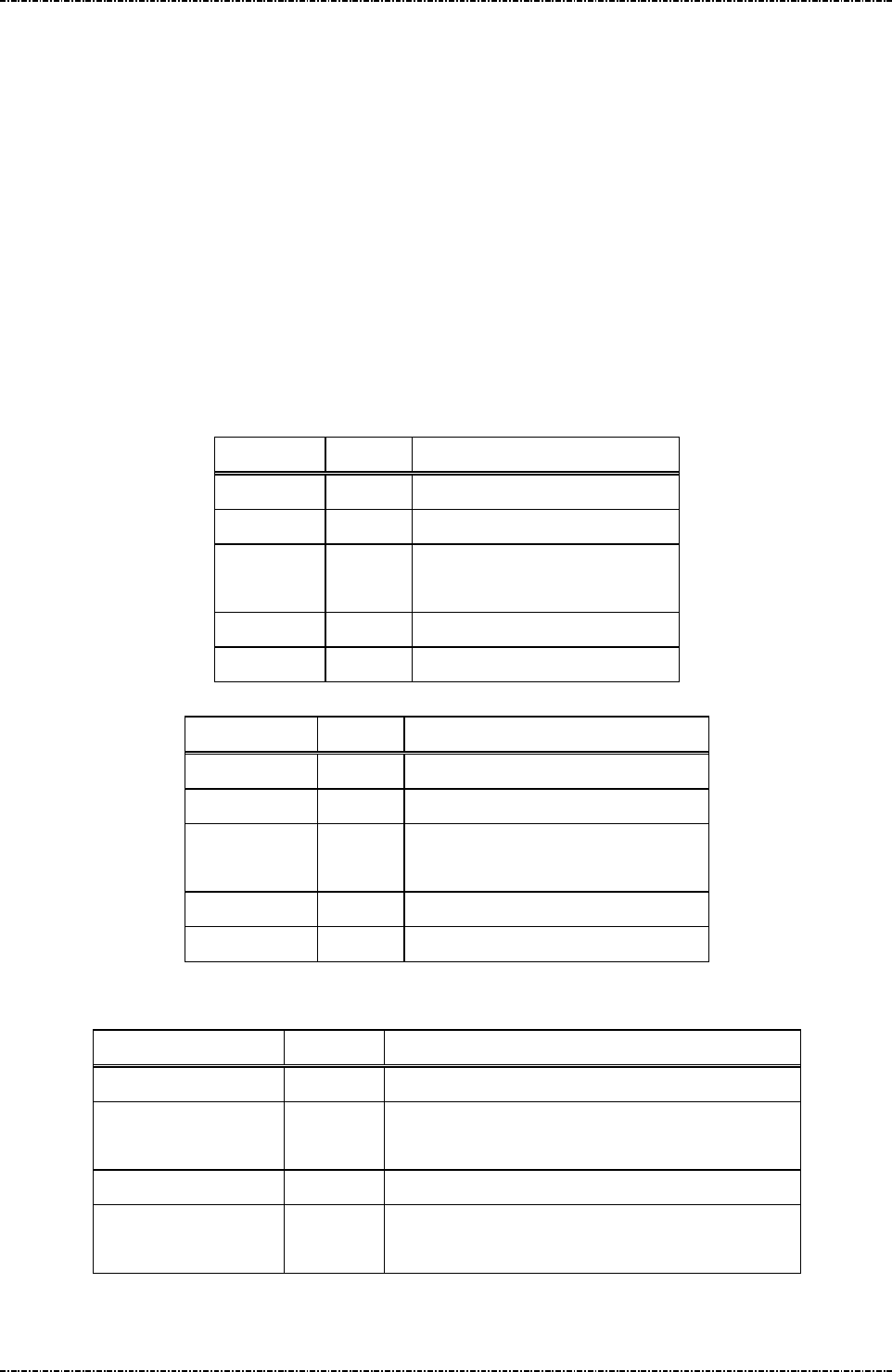
PIN Pad 791 Programmer’s Manual (PCI POS-A) UDN PM0103-U Rev. 06
Section 11 – ICC / SAM / Magnetic stripe card manipulating messages 2015-04-20
Page287
Uniform Industrial Corp. Proprietary and Confidential Total 342 pages
Message QB MSR Device (Not) Always Detection
Format: <STX>QB[flag]<ETX>[LRC]
Message length: Fixed 6 bytes.
Usage: If the always detection is turned on, PIN pad will return the magnetic card data each
swipe under idle mode (Terminal does not have to issue message Q1 for each card
data). If this functionality is turned off, terminal should issue message Q1 to get the
magnetic card data.
Note. If the card track is all disabled (refer to message Q4), terminal will always get null magnetic card
data.
Message element: Request fame (HOST to PP791)
Field Length
Value and description
<STX> 1 <02>
QB 2 Message ID
[flag] 1 ‘0’: Not always detect
‘1’: Always detect.
<ETX> 1 <03>
[LRC] 1 Checksum
Response fame (PP791 to HOST)
Field Length
Value and description
<STX> 1 <02>
QB 2 Message ID
[status] 1 ‘0’ = Setup successfully
‘1’ = Invalid flag
<ETX> 1 <03>
[LRC] 1 Checksum
Message flow:
HOST Direction PIN pad
Message QB
<ACK> (Good LRC) / <NAK> (Bad LRC)
<EOT> (after 3 NAKs)
Message QB(response)
<ACK> / <NAK> /
<EOT>
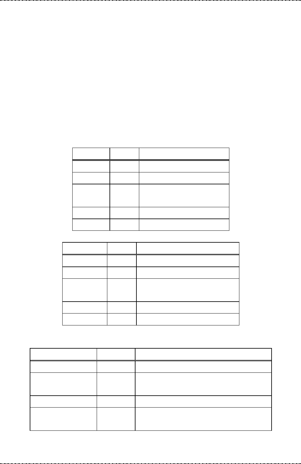
PIN Pad 791 Programmer’s Manual (PCI POS-A) UDN PM0103-U Rev. 06
Section 11 – ICC / SAM / Magnetic stripe card manipulating messages 2015-04-20
Page288
Uniform Industrial Corp. Proprietary and Confidential Total 342 pages
Message QC Contactless module (Not) Always Detection
Format: <STX>QC[flag]<ETX>[LRC]
Message length: Fixed 6 bytes.
Usage: If the always detection is turned on, PIN pad will return the contactless card data each
swipe under idle mode (Terminal does not have to issue message Q8/Q9 for each card
data). If this functionality is turned off, terminal should issue message Q8/Q9 to get the
contactless card data.
Note. If the card track is all disabled (refer to message QA), terminal will always get null magnetic card
data.
Message element: Request fame (HOST to PP791)
Field Length
Value and description
<STX> 1 <02>
QC 2 Message ID
[flag] 1 ‘0’: Not always detect
‘1’: Always detect.
<ETX> 1 <03>
[LRC] 1 Checksum
Response fame (PP791 to HOST)
Field Length
Value and description
<STX> 1 <02>
QC 2 Message ID
[status] 1 ‘0’ = Setup successfully
‘1’ = Invalid flag
<ETX> 1 <03>
[LRC] 1 Checksum
Message flow:
HOST Direction PIN pad
Message QC
<ACK> (Good LRC) / <NAK> (Bad LRC)
<EOT> (after 3 NAKs)
Message QB(response)
<ACK> / <NAK> /
<EOT>

PIN Pad 791 Programmer’s Manual (PCI POS-A) UDN PM0103-U Rev. 06
Section 11 – ICC / SAM / Magnetic stripe card manipulating messages 2015-04-20
Page289
Uniform Industrial Corp. Proprietary and Confidential Total 342 pages
Message QD Contactless Card Data with/without Start/End sentinels
Format: <STX>QD[flag]<ETX>[LRC]
Message length: Fixed 6 bytes.
Usage: The default value for PIN pad is to ignore the start/end sentinels and then return the
contactless card data. User can apply this message to make PIN pad return the
contactless card data with start/end sentinels.
Message element:
Request fame (HOST to PP791)
Field Length
Value and description
<STX> 1 <02>
QD 2 Message ID
. 1 <2E>
[flag] 1 ‘0’: Without Start/End sentinels
‘1’: With Start/End sentinels
<ETX> 1 <03>
[LRC] 1 Checksum
Response fame (PP791 to HOST)
Field Length
Value and description
<STX>
1 <02>
QD 2 Message ID
[status]
1 ‘0’: Without Start/End sentinels
‘1’: With Start/End sentinels
<ETX>
1 <03>
[LRC] 1 Checksum
Message flow:
HOST Direction PIN pad
Message QD
<ACK> (Good LRC)
<NAK> (Bad LRC)
<EOT> (after 3 NAKs)
Message QD (response)
<ACK> / <NAK> / <EOT>

PIN Pad 791 Programmer’s Manual (PCI POS-A) UDN PM0103-U Rev. 06
Section 11 – ICC / SAM / Magnetic stripe card manipulating messages 2015-04-20
Page290
Uniform Industrial Corp. Proprietary and Confidential Total 342 pages
Message 81 MSR Card Data
Format: <STX>81.[trk1 data]<FS>[trk2 data]<FS>[trk3 data]<FS>
[BIN record]<ETX>[LRC]
<STX>81@[trk1 data]<FS>[trk2 data]<FS>[trk3 data]<ETX>[LRC]
<STX>81&[Check PAN result 1]<FS>[Check PAN result 2]<ETX>[LRC]
Message length: Variable, depending on card image in buffer.
Usage: PIN pad uses this message to send back the information read from last card swipe.
Data are transmitted using ASCII string as defined by ISO 7811 format specification.
Under different type, PIN pad returns the card data in different format. If message Q4
is issued and PIN pad is set as track 2 only, the returned message 81 will contain only
track 2 data without filed separator.
If BIN table processing is enabled and a BIN record search is successful (Please refer
to message Exx for detailed information), the BIN will be attached in the end of
magnetic strip card data.
Message element:
Field Length Value and description
<STX> 1 <02>
81 2 Message ID
. 1 <2E>
[trk1] N Variable length, data of track 1.
<FS> 1 <1C>, field separator.
[trk2] N Variable length, data of track 2.
<FS> 1 <1C>, field separator.
[trk3] N Variable length, data of track 3.
<FS> 1 <1C>, filed separator, if BIN processing is
enabled and a match record is found.
[BIN
record]
16 Hex string. If BIN processing is enabled
and a match record is found.
<ETX> 1 <03>
[LRC] 1 Checksum

PIN Pad 791 Programmer’s Manual (PCI POS-A) UDN PM0103-U Rev. 06
Section 11 – ICC / SAM / Magnetic stripe card manipulating messages 2015-04-20
Page291
Uniform Industrial Corp. Proprietary and Confidential Total 342 pages
Message flow:
Under Operation Type 0, 1, 2 and 3
HOST Direction PIN pad
Message Q1 or Q9
“SWIPE CARD” displayed on LCD
<ACK> (Good LRC) / <NAK> (Bad LRC)
<EOT> (after 3 NAKs)
(User swipe magnetic card)
Message 81 (81.)
<ACK> (Good LRC)
<NAK> (Bad LRC)

PIN Pad 791 Programmer’s Manual (PCI POS-A) UDN PM0103-U Rev. 06
Section 11 – ICC / SAM / Magnetic stripe card manipulating messages 2015-04-20
Page292
Uniform Industrial Corp. Proprietary and Confidential Total 342 pages
Message 83 Contact-less Card Data
Format: <STX>83.[trk1 data]<FS>[trk2 data]<FS>[trk3 data]<ETX>[LRC]
Message length: Variable, depending on card image in buffer.
Usage: PIN pad uses this message to send back the information read from last contact-less
card tap. If message QA is issued and PIN pad is set as track 2 only, the returned
message 83 will contain only track 2 data without filed split.
Message element:
Field Length Value and description
<STX> 1 <02>
83 2 Message ID
. 1 <2E>
[trk1] N Variable length, data of track 1.
<FS> 1 <1C>, field separator.
[trk2] N Variable length, data of track 2.
<FS> 1 <1C>, field separator.
[trk3] N Variable length, data of track 3.
<ETX> 1 <03>
[LRC] 1 Checksum
Message flow: Please refer to message Q8 or Q9.

PIN Pad 791 Programmer’s Manual (PCI POS-A) UDN PM0103-U Rev. 06
Section 12 –Display functionality messages 2015-04-20
Page293
Uniform Industrial Corp. Proprietary and Confidential Total 342 pages
Section 12 Display functionality messages
PP791 provides a display with resolution 320x240 for graphic and 8*8, 8*16, 16*16 and 16*24 character
sets for text mode and supports many display functionalities for user.
Font size selection:
PP791 support 8*8 (0x20~0x7F), 8*16, 16*16 and 16*24 (0x20~0xFF) character sets for selection.
Foreground/Background color selection:
User can alternate the foreground and background color.
Screen save setting:
Set the parameters for screen save functionality.
Enable / disable screen save:
Enable or disable the screen save functionality.
Screen save preview:
The screen save will be launched once.
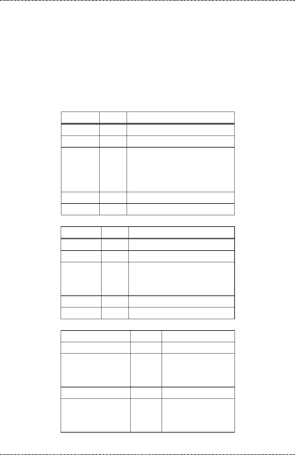
PIN Pad 791 Programmer’s Manual (PCI POS-A) UDN PM0103-U Rev. 06
Section 12 –Display functionality messages 2015-04-20
Page294
Uniform Industrial Corp. Proprietary and Confidential Total 342 pages
Message B1 Font Size Selection
Format: <STX>B1[Font Size]<ETX>[LRC] (request)
<STX>B2[Response]<ETX>[LRC] (response)
Message length: Fixed 6.
Usage: PIN pad supports 4 font sizes, 8x8, 8x16, 16x16 and 16x24. Use this message can
change the displayed font size. If the font size is set to 8x8, only the low page
characters can be displayed (<0x80), the high page characters will be replaced by
space character.
Request frame (HOST to PP791)
Field Length
Value and description
<STX> 1 <02>
B1 2 Message ID
[Font Size]
1 '0': 8x8 font size
'1': 8x16 font size
'2': 16x16 font size
'3': 16x24 font size
<ETX> 1 <03>
[LRC] 1 Checksum
Response frame (PP791 to HOST)
Field Length
Value and description
<STX> 1 <02>
B2 2 Message ID
[Response] 1 '0': Setup successfully.
'1': Format error
'2': Not support
<ETX> 1 <03>
[LRC] 1 Checksum
Message flow:
HOST Direction
PP791
Message B1 (Request)
<ACK> (Good LRC)
<NAK> (Bad LRC)
<EOT> (after 3 NAKs)
Message B2 (response)
<ACK> (Good echo)
<NAK> (Bad LRC)
<EOT> (after 3 NAKs)
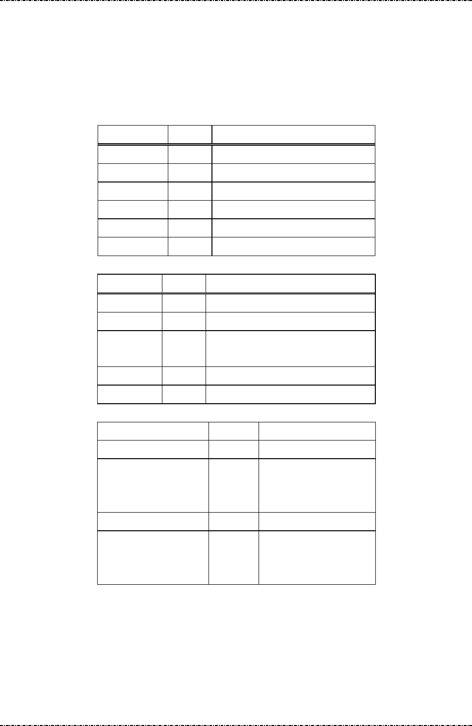
PIN Pad 791 Programmer’s Manual (PCI POS-A) UDN PM0103-U Rev. 06
Section 12 –Display functionality messages 2015-04-20
Page295
Uniform Industrial Corp. Proprietary and Confidential Total 342 pages
Message B3 Font Color (Foreground / Backgroud) Selection
Format: <STX>B3[Foreground][Background]<ETX>[LRC] (request)
<STX>B4[Response]<ETX>[LRC] (response)
Message length: Fixed 17 bytes.
Usage: Use this message to set new color of font and background. The format is RR/GG/BB.
Request frame (HOST to PP791)
Field Length
Value and description
<STX> 1 <02>
B3 2 Message ID
[Foreground]
6 Hex String. Format: RRGGBB
[Background]
6 Hex String. Format: RRGGBB
<ETX> 1 <03>
[LRC] 1 Checksum
Response frame (PP791 to HOST)
Field Length
Value and description
<STX> 1 <02>
B4 2 Message ID
[Response] 1 '0': Setup successfully.
'1': Format error
<ETX> 1 <03>
[LRC] 1 Checksum
Message flow:
HOST Direction
PP791
Message B3 (Request)
<ACK> (Good LRC)
<NAK> (Bad LRC)
<EOT> (after 3 NAKs)
Message B4 (response)
<ACK> (Good echo)
<NAK> (Bad LRC)
<EOT> (after 3 NAKs)
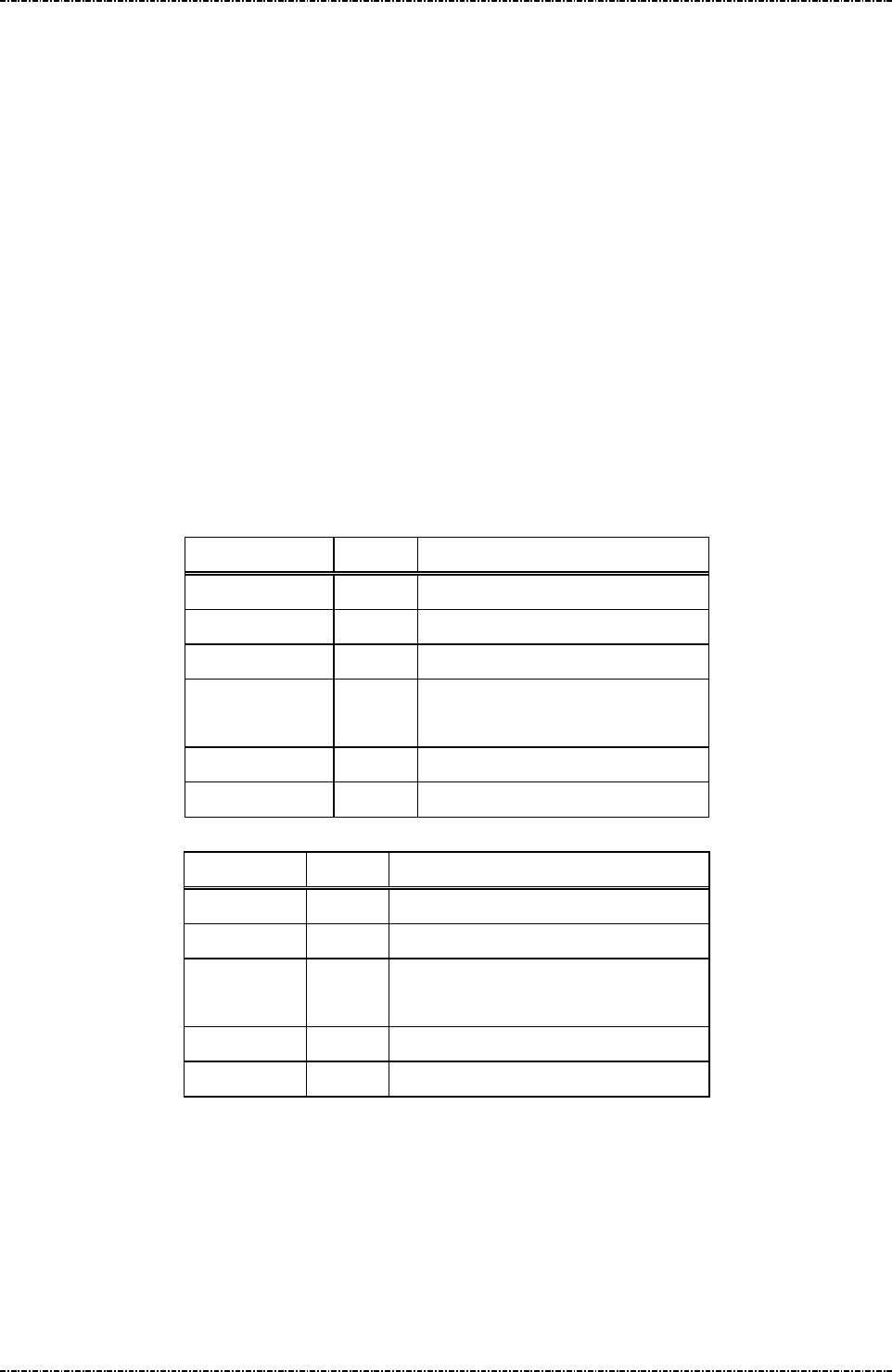
PIN Pad 791 Programmer’s Manual (PCI POS-A) UDN PM0103-U Rev. 06
Section 12 –Display functionality messages 2015-04-20
Page296
Uniform Industrial Corp. Proprietary and Confidential Total 342 pages
Message BB Screen Saver Setting
Format: <STX>BB[Waiting Time][Screen Saver Type]<ETX>[LRC] (request)
<STX>BC[Response]<ETX>[LRC] (response)
Message length: Fixed 9 bytes.
Usage: PP791 has screen saver functionality. Use this message to select one of screen
savers and set the waiting time, and use message BD to enable the screen saver.
While PP791 idles (without receiving messages, keystrokes, or screen touch) over the
time specified in [Waiting Time], the screen saver will be activated. The minimum
waiting time should be greater then or equal to 5 seconds.
Screen saver - Jpeg Show: display all jpeg pictures in rotation (at least one JPEG
image should be loaded into PP791).
Screen saves will be launched each time in rotation.
Request frame (HOST to PP791)
Field Length
Value and description
<STX> 1 <02>
BB 2 Message ID
[Waiting Time]
3 005~999
[Screen Saver
Type]
1 '1': Jpeg show
<ETX> 1 <03>
[LRC] 1 Checksum
Response frame (PP791 to HOST)
Field Length
Value and description
<STX> 1 <02>
BC 2 Message ID
[Response] 1 '0': Valid parameter.
'1': Invalid parameter.
<ETX> 1 <03>
[LRC] 1 Checksum

PIN Pad 791 Programmer’s Manual (PCI POS-A) UDN PM0103-U Rev. 06
Section 12 –Display functionality messages 2015-04-20
Page297
Uniform Industrial Corp. Proprietary and Confidential Total 342 pages
Message flow:
HOST Direction
PP791
Message BB (Request)
<ACK> (Good LRC)
<NAK> (Bad LRC)
<EOT> (after 3 NAKs)
Message BC (response)
<ACK> (Good echo)
<NAK> (Bad LRC)
<EOT> (after 3 NAKs)
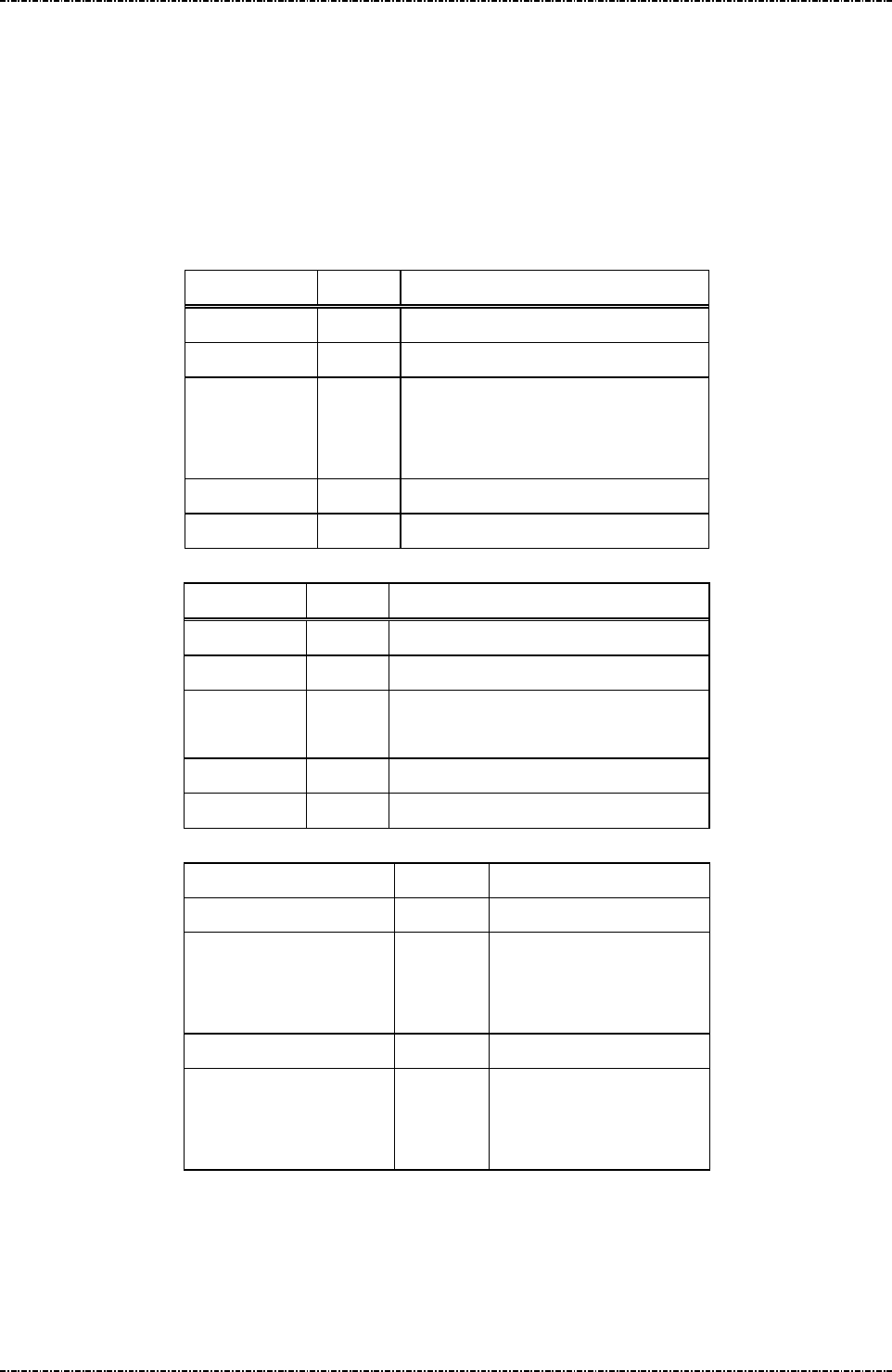
PIN Pad 791 Programmer’s Manual (PCI POS-A) UDN PM0103-U Rev. 06
Section 12 –Display functionality messages 2015-04-20
Page298
Uniform Industrial Corp. Proprietary and Confidential Total 342 pages
Message BD Enable / Disable Screen Saver
Format: <STX>BD[Op]<ETX>[LRC] (request)
<STX>BE[Response]<ETX>[LRC] (response)
Message length: Fixed 6 bytes.
Usage: Use this message to enable / disable screen saver.
Request frame (HOST to PP791)
Field Length
Value and description
<STX> 1 <02>
BD 2 Message ID
[Op] 1 '0': Disable screen saver
functionality.
'1': Enable screen saver functionality.
<ETX> 1 <03>
[LRC] 1 Checksum
Response frame (PP791 to HOST)
Field Length
Value and description
<STX> 1 <02>
BE 2 Message ID
[Response] 1 '0': Valid parameter.
'1': Invalid parameter.
<ETX> 1 <03>
[LRC] 1 Checksum
Message flow:
HOST Direction
PP791
Message BD (Request)
<ACK> (Good LRC)
<NAK> (Bad LRC)
<EOT> (after 3 NAKs)
Message BE (response)
<ACK> (Good echo)
<NAK> (Bad LRC)
<EOT> (after 3 NAKs)

PIN Pad 791 Programmer’s Manual (PCI POS-A) UDN PM0103-U Rev. 06
Section 12 –Display functionality messages 2015-04-20
Page299
Uniform Industrial Corp. Proprietary and Confidential Total 342 pages
Message BFScreen Saver Preview / Stop Preview
Format: <STX>BF[Op]<ETX>[LRC] (request)
Message length: Fixed 6 bytes.
Usage: Use this message to launch screen saver directly or turn it off. User can also issue any
other message to turn off screen saver.
Request frame (HOST to PP791)
Field Length
Value and description
<STX> 1 <02>
BF 2 Message ID
[Op] 1 '0': Stop screen saver preview
'1': Screen Saver Preview
<ETX> 1 <03>
[LRC] 1 Checksum
Message flow:
HOST Direction
PP791
Message BF (Request)
<ACK> (Good LRC)
<NAK> (Bad LRC)
<EOT> (after 3 NAKs)

PIN Pad 791 Programmer’s Manual (PCI POS-A) UDN PM0103-U Rev. 06
Section 13 – JPEG File Operation messages 2015-04-20
Page300
Uniform Industrial Corp. Proprietary and Confidential Total 342 pages
Section 13 JPEG File Operation messages
PP791 supports several JPEG file operation messages, customer could use JPEG Tool provided by UIC
to query PIN pad to get a JPEG file table, and customer could delete the existed JPEG files from PIN pad
and could select JPEG files for play. In addition, customer could download a JPEG file into PIN pad or
upload a JPEG file from PIN pad. Below are JPEG file operation messages those PP791 supports:
J0 JPEG File Table Initialization
J1 Query JPEG File Table
J2 Select JPEG File
J3 Delete JPEG File
J4 Download JPEG File
J5 Upload JPEG File
J6 Play JPEG File
J7 Set JPEG File As Idle Prompt
J8 Enable/Disable Idle Logo Functionality
J9 Show JPEG File
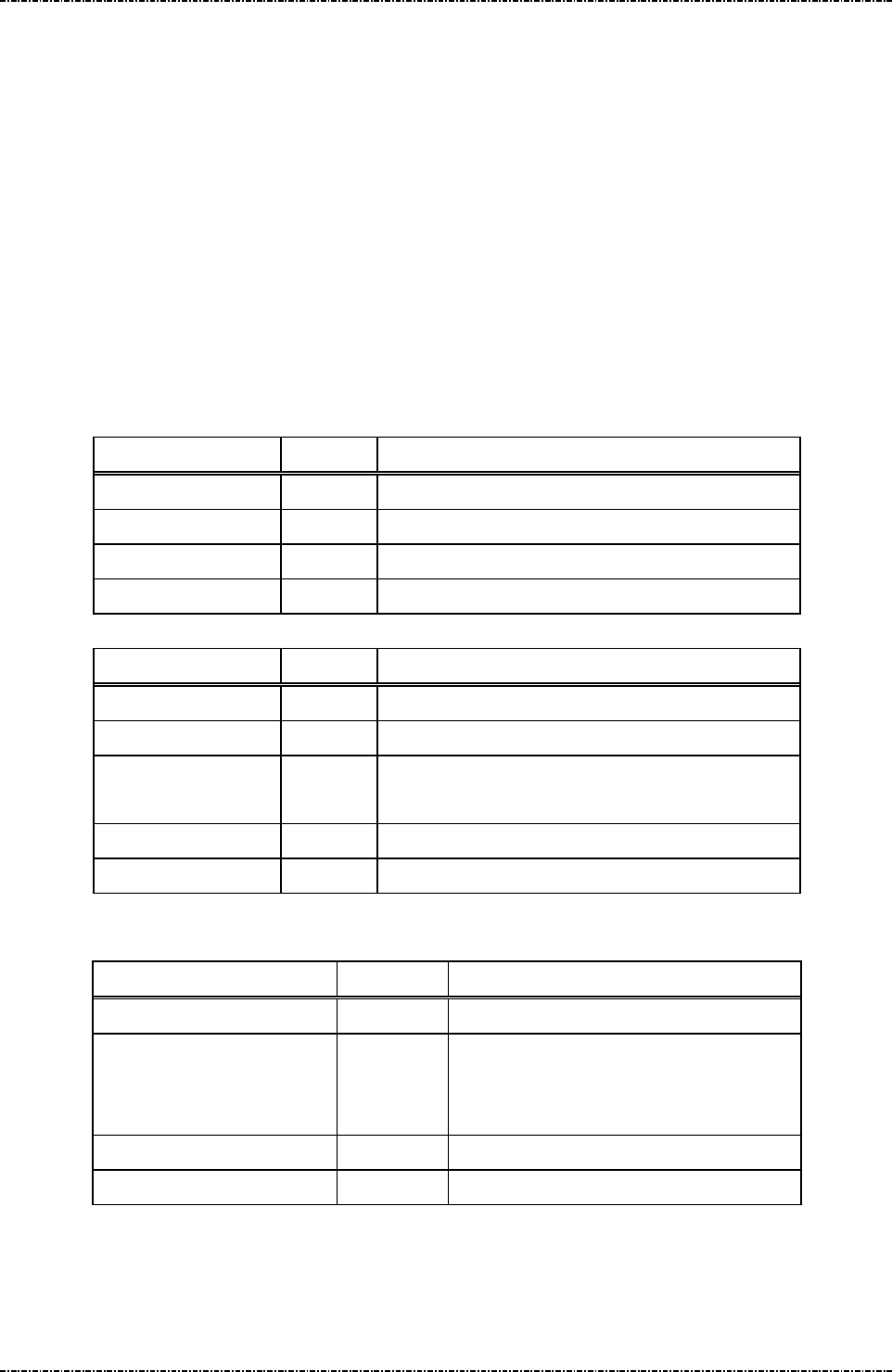
PIN Pad 791 Programmer’s Manual (PCI POS-A) UDN PM0103-U Rev. 06
Section 13 – JPEG File Operation messages 2015-04-20
Page301
Uniform Industrial Corp. Proprietary and Confidential Total 342 pages
Message J0 JPEG File Table Initialization
Format: <STX>J0<ETX>[LRC]
Request frame (HOST to PIN Pad)
<STX>J0[Status]<ETX>[LRC]
Response frame (PIN Pad to HOST)
Message length: Fixed 5 bytes for request frame and 6 bytes for response frame.
Usage: This message is used to initialize the JPEG file table from terminal.
Message element:
Request frame (HOST to PIN Pad)
Field Length Value and description
<STX> 1 <02>
J0 2 Message ID
<ETX> 1 <03>
[LRC] 1 Checksum
Response frame (PIN Pad to HOST)
Field Length Value and description
<STX> 1 <02>
J0 2 Message ID
[Status] 1 '0': Success.
'1': Failure.
<ETX> 1 <03>
[LRC] 1 Checksum
Message flow:
HOST Direction PIN Pad
Message J0
<ACK> (Good LRC)
<NAK> (Bad LRC)
<EOT> (after 3 NAKs)
Message J0
<ACK> / <NAK> / <EOT>
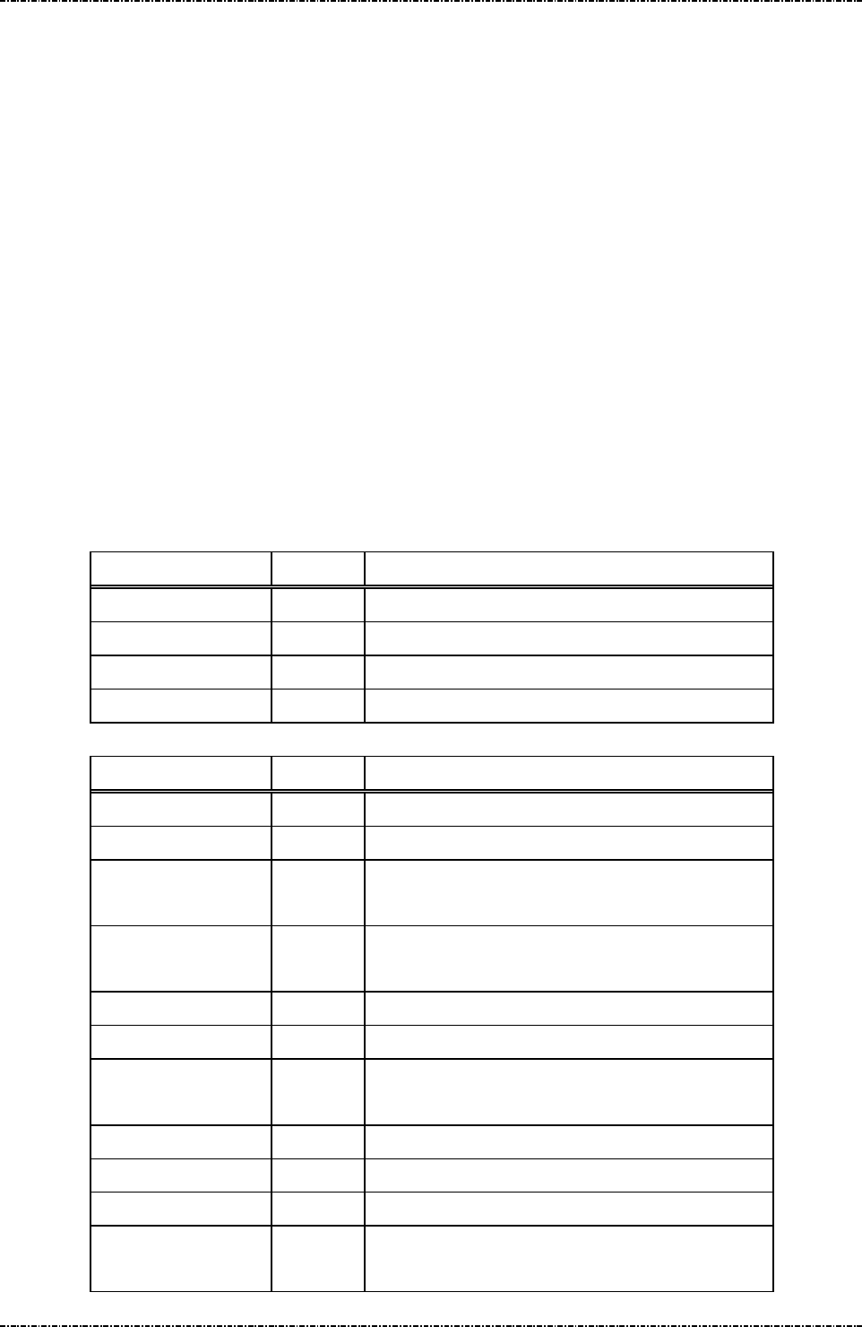
PIN Pad 791 Programmer’s Manual (PCI POS-A) UDN PM0103-U Rev. 06
Section 13 – JPEG File Operation messages 2015-04-20
Page302
Uniform Industrial Corp. Proprietary and Confidential Total 342 pages
Message J1 Query JPEG File Table
Format: <STX>J1<ETX>[LRC]
Request frame (HOST to PIN Pad)
<STX>J1[PktType][Status_1][FileName_1]<FS>
[Status_2][FileName_2]<FS>...
[Status_N-1][FileName_N-1]<FS>
[Status_N][FileName_N]<ETX>[LRC]
(where the value of 'N' is total amount of the JPEG files)
Response frame (PIN Pad to HOST)
Message length: Fixed 5 bytes for request frame and variable 5 to 540 bytes for response frame.
Usage: This message is used to query JPEG file table from terminal.
Message element:
Request frame (HOST to PIN Pad)
Field Length Value and description
<STX> 1 <02>
J1 2 Message ID
<ETX> 1 <03>
[LRC] 1 Checksum
Response frame (PIN Pad to HOST)
Field Length Value and description
<STX> 1 <02>
J1 2 Message ID
[PktType] 1 '0' = first or middle of multiple packets.
'1' = last or only packet.
[Status_1] 1 '0': Unselect. (optional)
'1': Select.
[FileName_1] 1-15 File name 1 (optional)
<FS> 1 <1C>, field separator (optional)
[Status_2] 1 '0': Unselect. (optional)
'1': Select.
[FileName_2] 1-15 File name 2 (optional)
<FS> 1 <1C>, field separator (optional)
………………… …….. …………………………………..
[Status_N-1] 1 '0': Unselect. (optional)
'1': Select.

PIN Pad 791 Programmer’s Manual (PCI POS-A) UDN PM0103-U Rev. 06
Section 13 – JPEG File Operation messages 2015-04-20
Page303
Uniform Industrial Corp. Proprietary and Confidential Total 342 pages
[FileName_N-1] 1-15 File name N-1 (optional)
<FS> 1 <1C>, field separator (optional)
[Status_N] 1 '0': Unselect. (optional)
'1': Select.
[FileName_N] 1-15 File name N (optional)
<ETX> 1 <03>
[LRC] 1 Checksum
Message flow:
HOST Direction PIN Pad
Message J1
<ACK> (Good LRC)
<NAK> (Bad LRC)
<EOT> (after 3 NAKs)
Message J1 ([PktType] = '0')
<ACK> / <NAK> / <EOT>
Message J1
<ACK> / <NAK> / <EOT>
Message J1 ([PktType] = '1')
<ACK> / <NAK> / <EOT>

PIN Pad 791 Programmer’s Manual (PCI POS-A) UDN PM0103-U Rev. 06
Section 13 – JPEG File Operation messages 2015-04-20
Page304
Uniform Industrial Corp. Proprietary and Confidential Total 342 pages
Message J2 Select JPEG File
Format: <STX>J2[control][FileName_1]<FS>[FileName_2]<FS>...
[FileName_N-1]<FS>[FileName_N]<ETX>[LRC]
(where the value of 'N' is total amount of the JPEG files)
Request frame (HOST to PIN Pad)
<STX>J2[Status_1]<FS>[Status_2]<FS>...
[Status_N-1]<FS>[Status_N]<ETX>[LRC]
(where the value of 'N' is total amount of the JPEG files)
Response frame (PIN Pad to HOST)
Message length: Variable 7 to 540 bytes for request frame, and variable 5 to 44 bytes for response
frame.
Usage: This message is used to select or unselect JPEG files from terminal’s display list.
Message element:
Request frame (HOST to PIN Pad)
Field Length Value and description
<STX> 1 <02>
J2 2 Message ID
[control] 1 '0': Unselect.
'1': Select.
[FileName_1] 1-15 File name 1
<FS> 1 <1C>, field separator (optional)
[FileName_2] 1-15 File name 2 (optional)
<FS> 1 <1C>, field separator (optional)
………………… …….. …………………………………..
[FileName_N-1] 1-15 File name N-1 (optional)
<FS> 1 <1C>, field separator (optional)
[FileName_N] 1-15 File name N (optional)
<ETX> 1 <03>
[LRC] 1 Checksum

PIN Pad 791 Programmer’s Manual (PCI POS-A) UDN PM0103-U Rev. 06
Section 13 – JPEG File Operation messages 2015-04-20
Page305
Uniform Industrial Corp. Proprietary and Confidential Total 342 pages
Response frame (PIN Pad to HOST)
Field Length Value and description
<STX> 1 <02>
J2 2 Message ID
[Status_1] 1 '0': Success, '1': Failure, '2': Format error.
<FS> 1 <1C>, field separator (optional)
[Status_2] 1 '0': Success, '1': Failure. (optional)
<FS> 1 <1C>, field separator (optional)
………………… …….. …………………………………..
[Status_N-1] 1 '0': Success, '1': Failure. (optional)
<FS> 1 <1C>, field separator (optional)
[Status_N] 1 '0': Success, '1': Failure. (optional)
<ETX> 1 <03>
[LRC] 1 Checksum
Message flow:
HOST Direction PIN Pad
Message J2
<ACK> (Good LRC)
<NAK> (Bad LRC)
<EOT> (after 3 NAKs)
Message J2
<ACK> / <NAK> / <EOT>

PIN Pad 791 Programmer’s Manual (PCI POS-A) UDN PM0103-U Rev. 06
Section 13 – JPEG File Operation messages 2015-04-20
Page306
Uniform Industrial Corp. Proprietary and Confidential Total 342 pages
Message J3 Delete JPEG File
Format: <STX>J3[FileName_1]<FS>[FileName_2]<FS>...
[FileName_N-1]<FS>[FileName_N]<ETX>[LRC]
(where the value of 'N' is total amount of the JPEG files)
Request frame (HOST to PIN Pad)
<STX>J3[Status_1]<FS>[Status_2]<FS>...
[Status_N-1]<FS>[Status_N]<ETX>[LRC]
(where the value of 'N' is total amount of the JPEG files)
Response frame (PIN Pad to HOST)
Message length: Variable 6 to 540 bytes for request frame, and variable 5 to 44 bytes for response
frame.
Usage: This message is used to delete JPEG files from terminal’s display list.
Message element:
Request frame (HOST to PIN Pad)
Field Length Value and description
<STX> 1 <02>
J3 2 Message ID
[FileName_1] 1-15 File name 1
<FS> 1 <1C>, field separator (optional)
[FileName_2] 1-15 File name 2 (optional)
<FS> 1 <1C>, field separator (optional)
………………… …….. …………………………………..
[FileName_N-1] 1-15 File name N-1 (optional)
<FS> 1 <1C>, field separator (optional)
[FileName_N] 1-15 File name N (optional)
<ETX> 1 <03>
[LRC] 1 Checksum

PIN Pad 791 Programmer’s Manual (PCI POS-A) UDN PM0103-U Rev. 06
Section 13 – JPEG File Operation messages 2015-04-20
Page307
Uniform Industrial Corp. Proprietary and Confidential Total 342 pages
Response frame (PIN Pad to HOST)
Field Length Value and description
<STX> 1 <02>
J3 2 Message ID
[Status_1] 1 '0': Success, '1': Failure, '2': Format error.
<FS> 1 <1C>, field separator (optional)
[Status_2] 1 '0': Success, '1': Failure. (optional)
<FS> 1 <1C>, field separator (optional)
………………… …….. …………………………………..
[Status_N-1] 1 '0': Success, '1': Failure. (optional)
<FS> 1 <1C>, field separator (optional)
[Status_N] 1 '0': Success, '1': Failure. (optional)
<ETX> 1 <03>
[LRC] 1 Checksum
Message flow:
HOST Direction PIN Pad
Message J3
<ACK> (Good LRC)
<NAK> (Bad LRC)
<EOT> (after 3 NAKs)
Message J3
<ACK> / <NAK> / <EOT>

PIN Pad 791 Programmer’s Manual (PCI POS-A) UDN PM0103-U Rev. 06
Section 13 – JPEG File Operation messages 2015-04-20
Page308
Uniform Industrial Corp. Proprietary and Confidential Total 342 pages
Message J4 Download JPEG File
Format: <STX>J4[PktType][SeqNo][Force]<FS>
[FileName]<FS>[Size][Data]<ETX>[LRC]
Request frame (HOST to PIN Pad)
<STX>J4[Status]<ETX>[LRC]
Response frame (PIN Pad to HOST)
Message length: Variable 22 to 538 bytes for request frame, and fixed 6 bytes for response frame.
Usage: This message is used to download a JPEG file from terminal.
Message element:
Request frame (HOST to PIN Pad)
Field Length Value and description
<STX> 1 <02>
J4 2 Message ID
[PktType] 1 '0' = first or middle of multiple packets.
'1' = last or only packet.
[SeqNo] 3 '000' to '999', for onetime only packet, set to '000'.
[Foce] 1 '0' = ask before overwrite, '1' = force overwrite
<FS> 1 <1C>, field separator
[FileName] 0-15 JPEG file name (optional)
<FS> 1 <1C>, field separator
[Size] 3 '000' to '523', size of [ImgData] in bytes
[ImgData] 0-523 Base 64 format data (optional)
<ETX> 1 <03>
[LRC] 1 Checksum
Response frame (PIN Pad to HOST)
Field Length Value and description
<STX> 1 <02>
J4 2 Message ID
[Status] 1 '0': Ready for next J4 packet.
'1': [PktType] has invalid value.
'2': [SeqNo] has invalid value.
'3': [Force] has invalid value.
'4': [FileName] has invalid value.
'5': [Size] has invalid value.
'6': [ImgData] has invalid value.

PIN Pad 791 Programmer’s Manual (PCI POS-A) UDN PM0103-U Rev. 06
Section 13 – JPEG File Operation messages 2015-04-20
Page309
Uniform Industrial Corp. Proprietary and Confidential Total 342 pages
'7': Number of <FS> is wrong.
'A': File size is zero or too large.
'B': Null file name.
'C': File name is too long or user abort.
'D': No more space.
'E': File is too large to stored to exist file's location.
'F': Download Success.
<ETX> 1 <03>
[LRC] 1 Checksum
Message flow:
HOST Direction PIN Pad
Message J4
([PktType] = '0' and [SeqNo] = '000')
<ACK> (Good LRC)
<NAK> (Bad LRC)
<EOT> (after 3 NAKs)
Message J4 ([Status] = '0')
<ACK> / <NAK> / <EOT>
Message J4
([PktType] = '0' and [SeqNo] = '001'-'998')
<ACK> / <NAK> / <EOT>
Message J4 ([Status] = '0')
………………………………….. …….. …………………
<ACK> / <NAK> / <EOT>
Message J4 ([PktType] = '1')
<ACK> / <NAK> / <EOT>
Message J4 ([Status] = 'F')
<ACK> / <NAK> / <EOT>
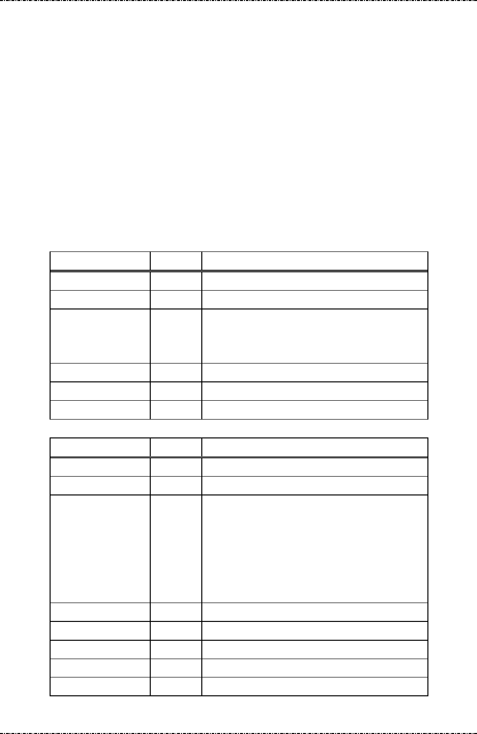
PIN Pad 791 Programmer’s Manual (PCI POS-A) UDN PM0103-U Rev. 06
Section 13 – JPEG File Operation messages 2015-04-20
Page310
Uniform Industrial Corp. Proprietary and Confidential Total 342 pages
Message J5 Upload JPEG File
Format: <STX>J5[control]<FS>[FileName]<ETX>[LRC]
Request frame (HOST to PIN Pad)
<STX>J5[PktType][SeqNo][Size][Data]<ETX>[LRC]
Response frame (PIN Pad to HOST)
Message length: Variable 6 to 21 bytes for request frame, and variable 12 to 536 bytes for response
frame.
Usage: This message is used to upload a JPEG file from terminal.
Message element:
Request frame (HOST to PIN Pad)
Field Length Value and description
<STX> 1 <02>
J5 2 Message ID
[control] 1 '0': First command for upload, [FileName] is
required.
'1': Ready for next J5 packet, [FileName] is ignored.
[FileName] 1-15 File name (Option)
<ETX> 1 <03>
[LRC] 1 Checksum
Response frame (PIN Pad to HOST)
Field Length Value and description
<STX> 1 <02>
J5 2 Message ID
[PktType] 1 '0' = First or middle of multiple packets.
'1' = Last or only packet.
'2': Null file name.
'3': File name is not found.
'4': Buffer is not enough.
'5': Format error.
[SeqNo] 3 '000' to '999', for onetime only packet, set to '000'.
[Size] 3 '000' to '524', size of [Data] in bytes
[Data] 0-524 Base 64 format data
<ETX> 1 <03>
[LRC] 1 Checksum

PIN Pad 791 Programmer’s Manual (PCI POS-A) UDN PM0103-U Rev. 06
Section 13 – JPEG File Operation messages 2015-04-20
Page311
Uniform Industrial Corp. Proprietary and Confidential Total 342 pages
Message flow:
HOST Direction PIN Pad
Message J5
([control] = '0')
<ACK> (Good LRC)
<NAK> (Bad LRC)
<EOT> (after 3 NAKs)
Message J5
([PktType] = '0' and [SeqNo] = '000')
<ACK> / <NAK> / <EOT>
Message J5
([control] = '1')
<ACK> / <NAK> / <EOT>
Message J5
([PktType] = '0' and [SeqNo] = '001'-'998')
<ACK> / <NAK> / <EOT>
………………… …….. …………………………………..
Message J5
([control] = '1')
<ACK> / <NAK> / <EOT>
Message J5
([PktType] = '1')
<ACK> / <NAK> / <EOT>
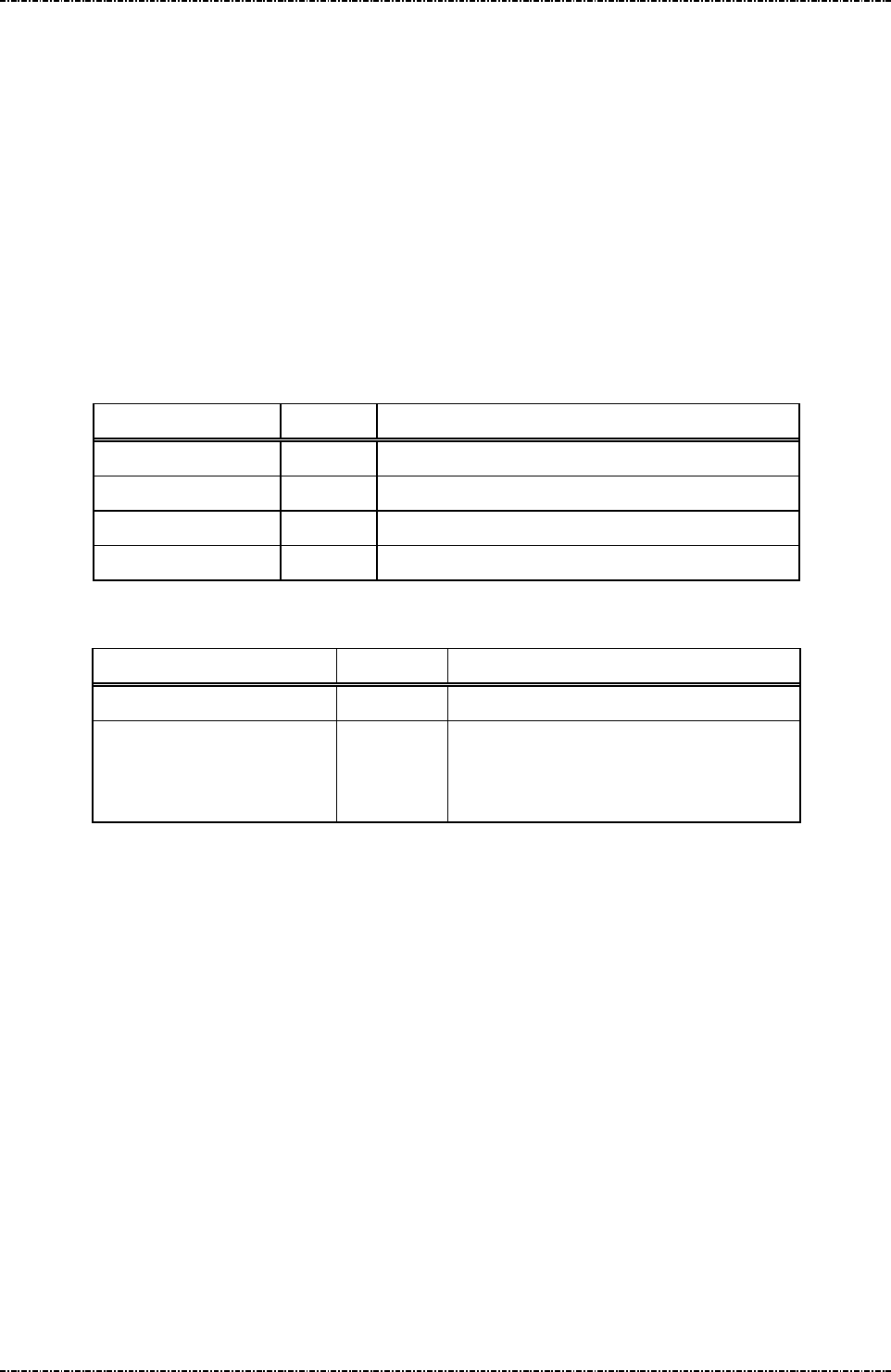
PIN Pad 791 Programmer’s Manual (PCI POS-A) UDN PM0103-U Rev. 06
Section 13 – JPEG File Operation messages 2015-04-20
Page312
Uniform Industrial Corp. Proprietary and Confidential Total 342 pages
Message J6 Play JPEG File
Format: <STX>J6<ETX>[LRC]
Request frame (HOST to PIN Pad)
Message length: Fixed 5 bytes.
Usage: This message is used to play the JPEG files those have been selected from terminal.
Those selected Jpeg files will be showed up sequentially until any operation (swiping
card, pressing any key, tapping screen or receiving command) that changes the display.
Message element:
Request frame
Field Length Value and description
<STX> 1 <02>
J6 2 Message ID
<ETX> 1 <03>
[LRC] 1 Checksum
Message flow:
HOST Direction PIN Pad
Message J6
<ACK> (Good LRC)
<NAK> (Bad LRC)
<EOT> (after 3 NAKs)
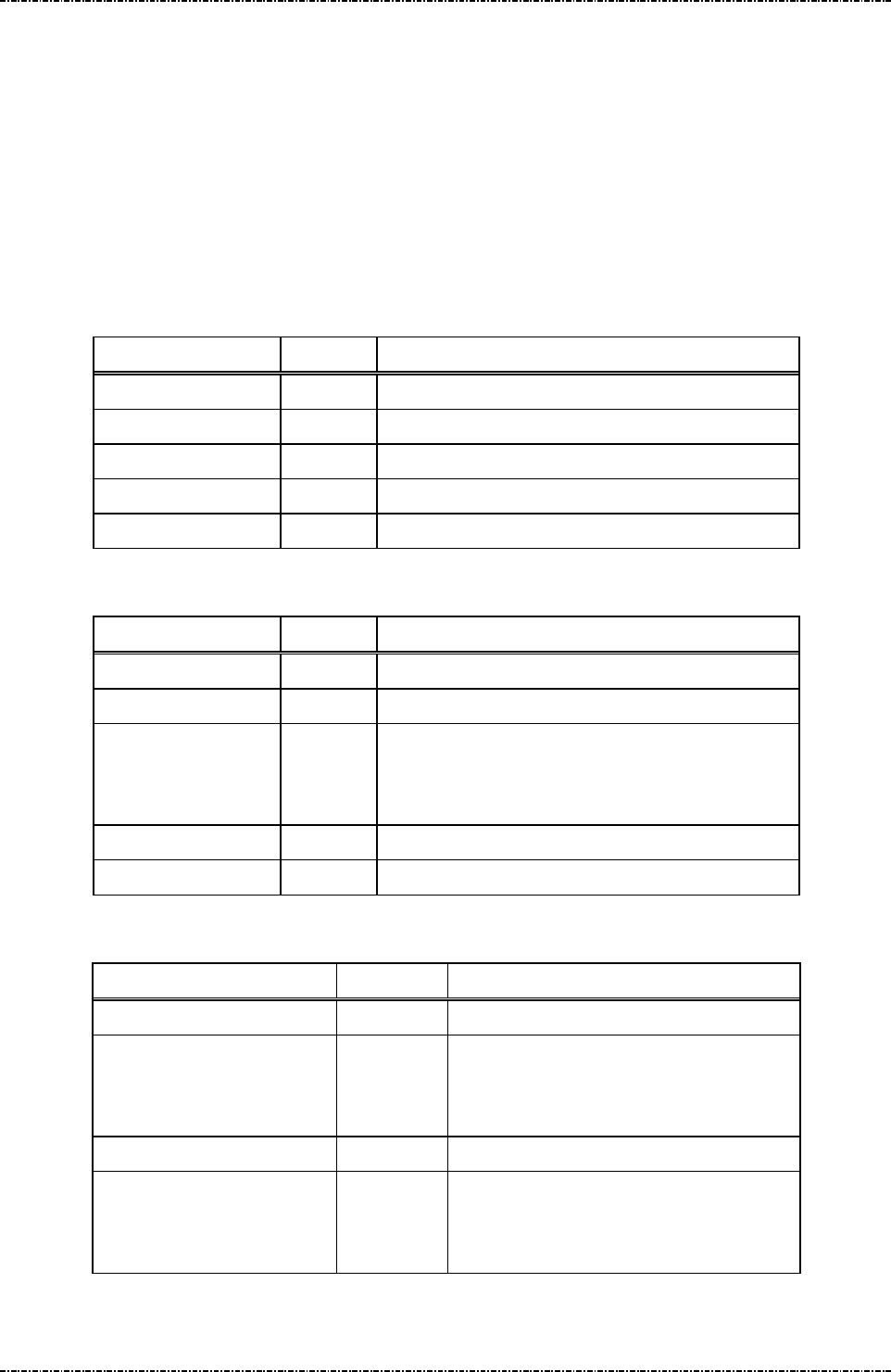
PIN Pad 791 Programmer’s Manual (PCI POS-A) UDN PM0103-U Rev. 06
Section 13 – JPEG File Operation messages 2015-04-20
Page313
Uniform Industrial Corp. Proprietary and Confidential Total 342 pages
Message J7 Set JPEG File As Idle Prompt
Format: <STX>J7[Jpeg Name]<ETX>[LRC] (request frame)
<STX>J7[Result]<ETX>[LRC] (response frame)
Message length: Variable 6 ~ 20 byte.
Usage: This message is used to set a JPEG file as idle logo.
Message element:
Request frame (HOST to PIN pad)
Field Length Value and description
<STX> 1 <02>
J7 2 Message ID
[Jpeg Name] 1~15 ASCII string, Jpeg file name.
<ETX> 1 <03>
[LRC] 1 Checksum
Response frame (PIN pad to HOST)
Field Length Value and description
<STX> 1 <02>
J7 2 Message ID
[Result] 1 '0' = Setup successfully.
'1' = Invalid length of file name.
'2' = Fail to setup.
<ETX> 1 <03>
[LRC] 1 Checksum
Message flow:
HOST Direction PIN Pad
Message J7
<ACK> (Good LRC)
<NAK> (Bad LRC)
<EOT> (after 3 NAKs)
Message J7 (response)
<ACK> (Good echo)
<NAK> (Bad LRC)
<EOT> (after 3 NAKs)
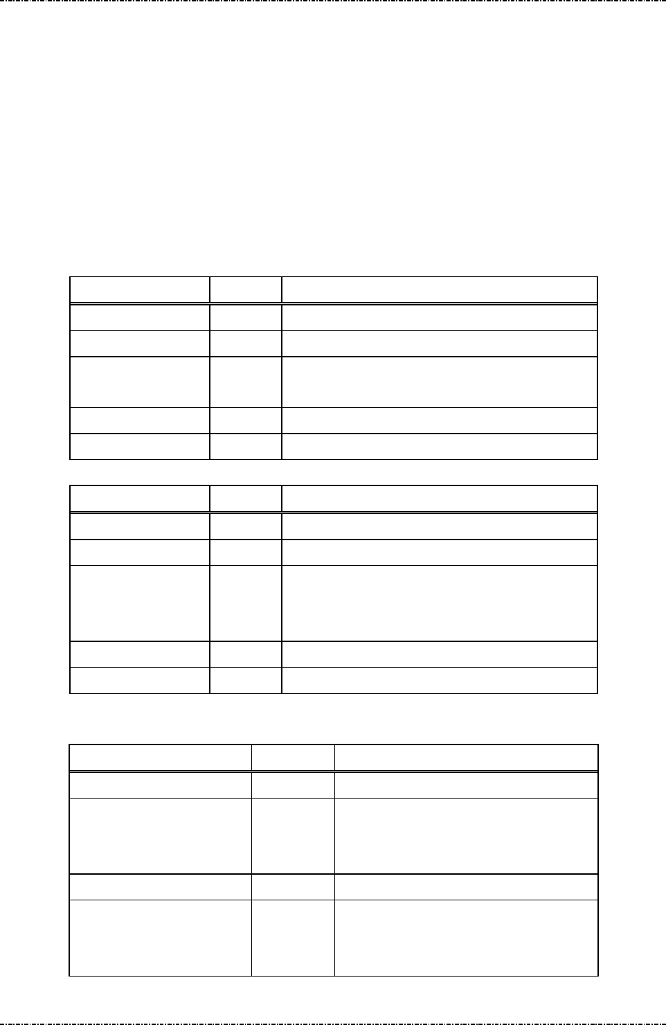
PIN Pad 791 Programmer’s Manual (PCI POS-A) UDN PM0103-U Rev. 06
Section 13 – JPEG File Operation messages 2015-04-20
Page314
Uniform Industrial Corp. Proprietary and Confidential Total 342 pages
Message J8 Enable/Disable Idle Logo Functionality
Format: <STX>J8[Op]<ETX>[LRC] (request frame)
<STX>J8[Result]<ETX>[LRC] (response frame)
Message length: Fixed 6 byte.
Usage: This message is used to enable/disable idle logo functionality. When it is enabled, idle
logo and date/time will not be displayed. In order to successfully enable idle logo
functionality, there should be a JPEG file that is assigned as idle logo.
Message element:
Request frame (HOST to PIN pad)
Field Length Value and description
<STX> 1 <02>
J8 2 Message ID
[Op] 1 0 : Disable
1 : Enable
<ETX> 1 <03>
[LRC] 1 Checksum
Response frame (PIN pad to HOST)
Field Length Value and description
<STX> 1 <02>
J8 2 Message ID
[Result] 1 '0' = Setup successfully.
'1' = Invalid Op parameter.
‘2’ = Fail to setup (No Jpeg file is assigned)
<ETX> 1 <03>
[LRC] 1 Checksum
Message flow:
HOST Direction PIN Pad
Message J8
<ACK> (Good LRC)
<NAK> (Bad LRC)
<EOT> (after 3 NAKs)
Message J8 (response)
<ACK> (Good echo)
<NAK> (Bad LRC)
<EOT> (after 3 NAKs)
PIN Pad 791 Programmer’s Manual (PCI POS-A) UDN PM0103-U Rev. 06
Section 13 – JPEG File Operation messages 2015-04-20
Page315
Uniform Industrial Corp. Proprietary and Confidential Total 342 pages
Message J9 Show JPEG File
Format: <STX>J9[Jpeg Name]<ETX>[LRC] (request frame)
<STX>J9[Result]<ETX>[LRC] (response frame)
Message length: Variable 6 ~ 20 byte.
Usage: This message is used to make PIN pad show the assigned Jpeg file. The assigned Jpeg
file will be showed up once until any operation (pressing Cancel key or receiving
command) that changes the display.
Message element:
Request frame (HOST to PIN pad)
Field Length Value and description
<STX> 1 <02>
J9 2 Message ID
[Jpeg Name] 1~15 ASCII string, Jpeg file name.
<ETX> 1 <03>
[LRC] 1 Checksum
Response frame (PIN pad to HOST)
Field Length Value and description
<STX> 1 <02>
J9 2 Message ID
[Result] 1 '0' = Success.
'1' = Invalid length of file name.
'2' = No assigned Jpeg file.
<ETX> 1 <03>
[LRC] 1 Checksum

PIN Pad 791 Programmer’s Manual (PCI POS-A) UDN PM0103-U Rev. 06
Section 13 – JPEG File Operation messages 2015-04-20
Page316
Uniform Industrial Corp. Proprietary and Confidential Total 342 pages
Message flow:
HOST Direction PIN Pad
Message J9
<ACK> (Good LRC)
<NAK> (Bad LRC)
<EOT> (after 3 NAKs)
Message J9 (response)
<ACK> (Good echo)
<NAK> (Bad LRC)
<EOT> (after 3 NAKs)
The screen will not be changed until
pressing Cancel or receiving any
command.
PIN Pad 791 Programmer’s Manual (PCI POS-A) UDN PM0103-U Rev. 06
Section 13 – JPEG File Operation messages 2015-04-20
Page317
Uniform Industrial Corp. Proprietary and Confidential Total 342 pages
Message JA Set Boot Logo
Format: <STX>JA[PktType][SeqNo]<FS>[Size][Data]<ETX>[LRC]
Request frame (HOST to PIN Pad)
<STX>JA[Status]<ETX>[LRC]
Response frame (PIN Pad to HOST)
Message length: Variable 22 to 538 bytes for request frame, and fixed 6 bytes for response frame.
Usage: This message is used to download a bitmap file for boot logo from terminal .
Message element:
Request frame (HOST to PIN Pad)
Response frame (PIN Pad to HOST)
Field Length Value and description
<STX> 1 <02>
JA 2 Message ID
[Status] 1 '0': Ready for next JA packet.
'1': [PktType] has invalid value.
'2': [SeqNo] has invalid value.
'3': Number of <FS> is wrong.
'4': [Size] has invalid value.
'5': [ImgData] has invalid value.
'6': No more space.
'7': Bitmap file format error.
'F': Download Success.
<ETX> 1 <03>
[LRC] 1 Checksum
Field Length Value and description
<STX> 1 <02>
JA 2 Message ID
[PktType] 1 '0' = first or middle of multiple packets.
'1' = last or only packet.
[SeqNo] 3 '000' to '999', for onetime only packet, set to '000'.
<FS> 1 <1C>, field separator
[Size] 3 '000' to '525', size of [ImgData] in bytes
[ImgData] 0-525 Base 64 format data (optional)
<ETX> 1 <03>
[LRC] 1 Checksum

PIN Pad 791 Programmer’s Manual (PCI POS-A) UDN PM0103-U Rev. 06
Section 13 – JPEG File Operation messages 2015-04-20
Page318
Uniform Industrial Corp. Proprietary and Confidential Total 342 pages
Message flow:
HOST Direction PIN Pad
Message JA
([PktType] = '0' and [SeqNo] = '000')
<ACK> (Good LRC)
<NAK> (Bad LRC)
<EOT> (after 3 NAKs)
Message JA ([Status] = '0')
<ACK> / <NAK> / <EOT>
Message JA
([PktType] = '0' and [SeqNo] = '001'-'998')
<ACK> / <NAK> / <EOT>
Message JA ([Status] = '0')
………………………………….. …….. …………………
<ACK> / <NAK> / <EOT>
Message JA ([PktType] = '1')
<ACK> / <NAK> / <EOT>
Message JA ([Status] = 'F')
<ACK> / <NAK> / <EOT>

PIN Pad 791 Programmer’s Manual (PCI POS-A) UDN PM0103-U Rev. 06
Appendix A – Key management 2015-04-20
Page319
Uniform Industrial Corp. Proprietary and Confidential Total 342 pages
Appendix A Key management
This PIN pad is designed to encrypt Personal Identification Numbers (PIN) as they are entered from the
keypad, store the encrypted data in its memory and then transmit it to the HOST as requested.
Because the data-encryption standard (DES) and RSA algorithm are in the public domain, the security of
the functions of the PP791 depend on the security of the key that is used in processing the algorithm.
Therefore, after you load cryptographic keys into the PP791, the keys cannot be read. They are placed
AES encrypted by a randomly generated AES key, resident in a battery-powered register. Once security
is breached, the AES key will be erased, and all encrypted DES master keys become unusable.
You can design a secure method for handling your keys when you are isolated from the PIN keypad,
using the provisions for loading the keys. Randomly generate your keys, and store and distribute your
keys in a secure, controlled manner that you can audit.
An independent Tamper Resistant Security Module (TRSM) is required for secure key injection process.
UIC provides a software key injection utility (UICKIT for Windows) as demo for safely and manageable
key injection procedure. Please refer to UICKIT programming manual for detail.
PP791 supports following management schemes:
1. Master/session key (MK/SK):
PP791 can store 32 (16 keys for future use) master keys, key ID 0 to 9 are for MK/SK PIN entry
(They can be PIN master key or PIN key), key ID B to E is for generate or verify MAC, depend on
its usage and mode settings. (They can be MAC master key or MAC key), F for master key
transportation (It can be only key loading key) and G (It can be MSR master key or MSR data key)
for MSR data transportation. These master keys cannot be used in other ways (e.g. designer
cannot use PIN entry keys for MAC generation.) Session keys (working keys) are transmitted from
the HOST, encrypted by the master key for every transaction. Customer’s PIN is encrypted using
the decrypted working key or by selected master key (If the selected one is with key usage “P0”).
Thus the master keys must exist before any transaction can take place. PP791 can use 8 bytes
DES key format or 16 / 24 bytes Triple DES key format, the working key can also be 16 bytes
TDES key.
When doing transactions using MK/SK scheme, firmware of PP791 applies a DES calculation
count limiter (only 100 transactions are allowed in 5 minutes period.) to comply with PCI PED
security requirement (average one transaction per 30 seconds.) This constraint is set to deter
attacker using huge saturation DES transaction to detect master key in PP791.
2. ANSI TR31 Specified Key Bundle
Key Attribute:
When loading master keys into PP791 in encrypted format, the key data is wrapped by a key
bundle specified in ANSI TR-31 2010 specification.
1. Key usage: indicate what usage of a key.
“K0”, indicates that this key is used for key transportation;

PIN Pad 791 Programmer’s Manual (PCI POS-A) UDN PM0103-U Rev. 06
Appendix A – Key management 2015-04-20
Page320
Uniform Industrial Corp. Proprietary and Confidential Total 342 pages
“P0”, indicates that this key is used for PIN entry directly;
“D0”, indicates that this key is used for data transportation;
“M1” indicates that this key is used for MAC calculation directly by ISO 9797-1 method 1.
“M3” indicates that this key is used for MAC calculation directly by ISO 9797-1 method 3.
“B1”, indicates that this key is used for DUKPT initial key (ANSI TR-31 2010).
2. Algorithm: indicate what algorithm will be used with the key.
“D” : DES algorithm
“T”: TDES algorithm (double or triple length key)
“A”: AES algorithm (RFU)
3. Mode: indicate what cryptograph operation will be applied with the key
“D”: Decryption
“E”: Encryption
“G”: MAC generation
“V”: MAC verification
“X”: Key derivation (DUKPT)
4. Version (RFU): It should be 00.
5. Export (RFU): It should be “N”.
If the key usage is “K0”, the length of key must be 16 bytes or 24 bytes (algorithm must be “T”).
Key Architecture and limitation
Group Key ID
Length
Usage Algorithm
Mode
Encrypt under
PIN 0~9 8~24 P0 D or T E KLK
16~24
K0 T D KLK
Data A RFU RFU RFU RFU RFU
MAC B~E
8 M1 D G KLK
16 M3 T G / V
KLK
16~24
K0 T D KLK
KLK F 16~24
K0 T D KLK
MSR Data
G 8~24 D0 D or T E KLK
16~24
K0 T D KLK
RFU H~V
RFU RFU RFU RFU RFU
Key attribute and limitation for IPEK
IPEK Length
Usage Algorithm
Mode
Encrypt under
IPEK0
or
IPEK1
8 or 16
B1 D or T X KLK
1. All the keys injected in cipher-text must be encrypted by key derived from KLK and calculate a

PIN Pad 791 Programmer’s Manual (PCI POS-A) UDN PM0103-U Rev. 06
Appendix A – Key management 2015-04-20
Page321
Uniform Industrial Corp. Proprietary and Confidential Total 342 pages
MAC value by key derived from KLK
2. For key with usage “K0”, the length must be 16 bytes or 24 bytes.
3. For MAC key with usage “M1”, the length of key must be 8 bytes (DES-MAC).
4. For MAC key with usage “M3”, the length of key must be 16 bytes (TDES-MAC).
5. Duplicate key injection is not allowed. (except IPEK0 and IPEK1)
6. The length of injected key in cipher-text should be equal to or less then the length of KLK.
Key Injection
To inject clear-text key (Key ID: 0~9, A~G) into PP791, the default attributes will be as following,
Key usage = “K0”, Algorithm = “T”, Mode = “D”, Version = “00” and export = “N”
To inject cipher-text key into PP791, user has to assign these attributes.
For Key 0 ~ 9,
Key usage should be “K0” or “P0”, algorithm should be “T” or “D”, mode should be “D” (If for “K0”
usage) or “E” (If for “D0” usage).
For Key B ~ E,
Key usage should be “K0”, “M1” or “M3”, algorithm should be “T” (If for “K0” or “M3” usage) or “D”
(If for “M1” usage), mode should be “D” (If for “K0” usage) or “G” (If for “M1” or “M3” usage).
For Key G,
Key usage should be “K0” or “D0”, algorithm should be “T” (If for “K0”) or “D”.
For Key F,
Key usage should be “K0”, algorithm should be “T”.
For IPEK 0~1
Key usage could be any 2 bytes data, algorithm should be “D” or “T”, mode should be “E”.
Inject key in cipher-text (TR31 format)
For Key 0~9, A~G
<SI>02[Key ID][KBH][Encrypted KEY][MAC]<SO>, where [KBH] + [Encrypted KEY] + [MAC] is
TR31 block.
For IPEK0
<STX>90[KBH][Optional KBH][DUKPT0][MAC]<ETX>, where [KBH and Optional KBH] +
[IPEK0] + [MAC] is TR31 block.
For IPEK1
<STX>94[KBH][Optional KBH][DUKPT1][MAC]<ETX>, where [KBH and Optional KBH] +
[IPEK1] + [MAC] is TR31 block.
KBH (Key Block Header – ASCII format):
A[4byte – length of TR31 block][2byte - Usage][1byte - Algorithm] [1byte - Mode][2byte -
Version][1byte - Export][2byte - option][2byte - rfu]

PIN Pad 791 Programmer’s Manual (PCI POS-A) UDN PM0103-U Rev. 06
Appendix A – Key management 2015-04-20
Page322
Uniform Industrial Corp. Proprietary and Confidential Total 342 pages
Optional KBH (For DUKPT use only):
[2byte: Optional Block ID, fixed as “KS”][2byte: Optional Block Length, fixed as “18”][20byte:
Optional Block Data, put key serial number (refer to ANSI X9.24 SMID) in this field]
Encrypted KEY Block:
1. Derive Key1 by XOR KLK with 0x45
2. Generate new key block, [2byte number indicate the key in bits][key][random padding]
3. Encrypt the new key block by Key1 with first 8byte of KBH as IV in CBC mode and get
encrypted key block.
MAC:
1. Derive Key2 by XOR KLK with 0x4D
2. Concatenate KBH with Optional KBH (if any) and encrypted key block and get new key block
2.
3. Encrypt the new key block 2 by Key2 without IV in CBC mode and get the last 8 bytes.
4. Get the first 4 bytes of result as MAC value
Example 1:
KLK: 0123456789ABCDEFFEDCBA9876543210
New MK (Key ID = 1, key usage = “K0”): 89E88CF7931444F334BD7547FC3F380C
Generate KBH:
KBH = A | 0072 | K0 | T | D | 00 | N | 0000
Generate Encrypted KEY Block:
1. Derive K1 for encryption: 44660022CCEE88AABB99FFDD33117755
K2 for MAC value: 4C6E082AC4E680A2B391F7D53B197F5D
2. Key length = 16 bytes (128 bits = 0x80), 6 byte random padding = 720DF563BB07,
New key block = 008089E88CF7931444F334BD7547FC3F380C720DF563BB07.
3. IV = first 8 byte of KBH (“A0072K0T”) = 41303037324B3054, apply TDES-CBC on new
key block by K1 with IV and get encrypted key block = D078A2657E5B57972CD3
D308E05E1FE519B316309AA6354A
MAC:
1. Concatenate KBH and encrypted key block = 41303037324B30544430304E303
03030D078A2657E5B57972CD3 D308E05E1FE519B316309AA6354A
2. Apply TDES-CBC on new key block 2 by K2 without IV and get last 8 byte result =
668071B5B73CC024
3. MAC value = 668071B5
4. The final TR31 block = A0072K0TD00N0000 - D078A2657E5B57972CD3D308E05E
1FE519B316309AA6354A - 668071B5
Send message 02 to load this new key in cipher-text:

PIN Pad 791 Programmer’s Manual (PCI POS-A) UDN PM0103-U Rev. 06
Appendix A – Key management 2015-04-20
Page323
Uniform Industrial Corp. Proprietary and Confidential Total 342 pages
<SI>021A0072K0TD00N0000D078A2657E5B57972CD3D308E05E1FE519B316309AA6354A66
8071B5<SO>[LRC]
3. Derived Unique Key Per Transaction (DUKPT):
PP791 Implements ANSI X9.24-2002 and ANSI TR31 key management scheme for DUKPT.
Authorized personnel can load 8bytes/16bytes Initial keys (also known as IPEK) and Key serial
number (also known as ‘Security Management Information Data-SMID’ in ANSI X9.24). Every time
when PP791 finished a PIN entry transaction, a new key will be calculated. Every single
transaction will use different key in order to prevent attacker to detect specific keys in any
transactions.
The symmetric keys (MKSK/DUKPT) structure is shown as following:
Master Key 0
(PIN entry master keys / PIN keys)
Master Key 1
(PIN entry master keys / PIN keys)
…
Master Key 9
(PIN entry master keys / PIN keys)
...
Master Key B~E
(MAC master keys)
(MAC master keys / MAC keys)
Master Key F
(Key Loading Key)
Master Key G
(MSR master key / MSR data key)
Master Key H
(RFU)
Master Key I
(RFU)
…
Master Key V
4. RSA public key:
PP791 supports RSA encryption when processing EMV level 2 offline transactions with smart
cards.
DUKPT Set 0
DUKPT Set 1

PIN Pad 791 Programmer’s Manual (PCI POS-A) UDN PM0103-U Rev. 06
Appendix A – Key management 2015-04-20
Page324
Uniform Industrial Corp. Proprietary and Confidential Total 342 pages
5. Second DUKPT Key Set of PP791:
PP791 provides 2nd key set of DUKPT operation for customer’s scalability. Message 90 is used to
initialize first key set, with message 94 to initialize second key set. User must issue message 96 to
select preferred key set before doing DUKPT transactions. These two key set are independent
with each other, and both accepts double length key for TDES capability. Ether key set reaches
1million transaction limit will lock down PP791.
In real operation, authorized user can load a 8byte DES initial key to key set 1 and a 16byte TDES
initial key to key set 2 before PIN pad is deployed. At first use can transact with key set 1. When
backbone system ready, user can use message 96 to select key set 2 to switch to TDES
transaction immediately.
6. Triple DES (TDES) capability:
TDES means that DES algorithm is applied three times on the data to be encrypted before it is
sent over the line. PP791 can detect key length when loading keys (message 02 for
Master/Session key and message 90/94 for DUKPT) and doing transactions (Master/Session key
message 70, Z60, Z62). If a 32 or 48 characters (16 or 24 byte) key is used, PP791 will treat all
transactions using this key as TDES enabled, else PP791 use DES operation.
TDES algorithm needs a 16-byte key, which separated as L-key (leftmost 8 bytes) and R-key
(rightmost 8 bytes). PP791 defaults EDE order for TDES encrypting operation as follows:
Clear Text
DES
encryption
via L-key
DES
decryption
via R-key
DES
encryption
via L-key
Ciphered
Text
EDE order of TDES operation – 16 byte key. (Data decrypting process is the reverse of encrypting process.)
Clear Text
DES
encryption
via L-key
DES
decryption
via
Middle-key
DES
encryption
via R-key
Ciphered
Text
EDE order of TDES operation – 24 byte key. (Data decrypting process is the reverse of encrypting process.)
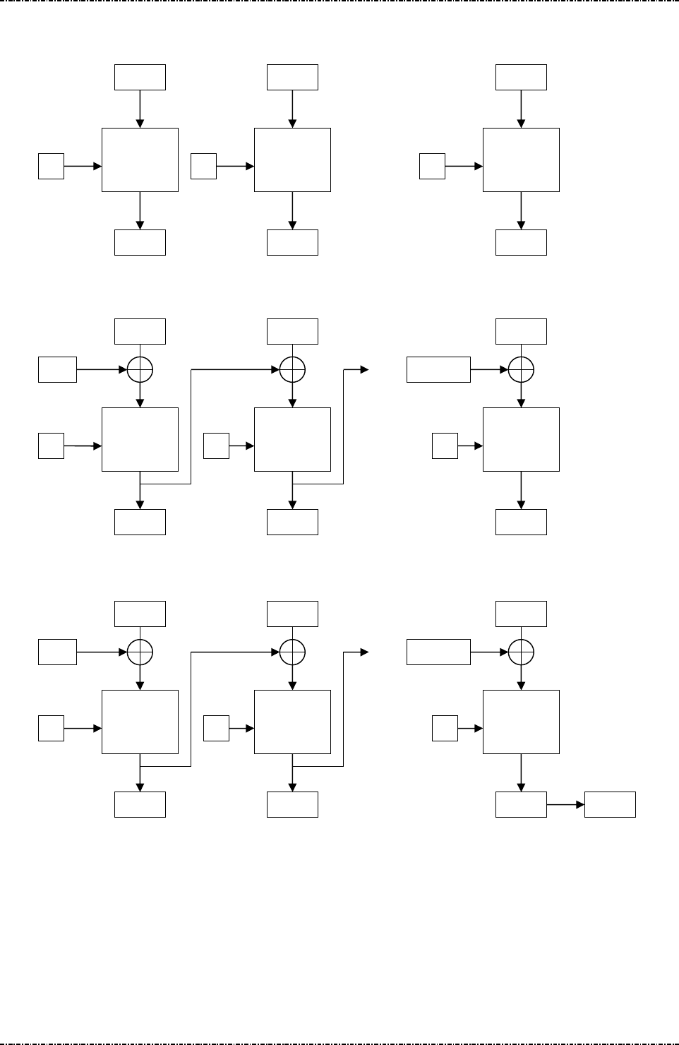
PIN Pad 791 Programmer’s Manual (PCI POS-A) UDN PM0103-U Rev. 06
Appendix A – Key management 2015-04-20
Page325
Uniform Industrial Corp. Proprietary and Confidential Total 342 pages
7. TDES – ECB Encryption:
8. TDES – CBC Encryption:
9. DES-MAC (ISO 9797-1 method 1)
D1 D2
TDES-E
TDES-E
K
K
…
DN
TDES-E
K
C1 C2 CN
D1 D2
TDES-E
TDES-E
K
K
…
DN
TDES-E
K
C1 C2 CN
IV
… CN-1
D1 D2
DES-E
DES-E
K
K
…
DN
DES-E
K
C1 C2 CN
IV
… CN-1
MAC
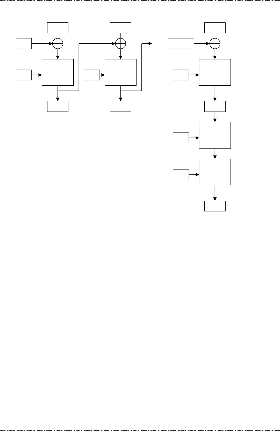
PIN Pad 791 Programmer’s Manual (PCI POS-A) UDN PM0103-U Rev. 06
Appendix A – Key management 2015-04-20
Page326
Uniform Industrial Corp. Proprietary and Confidential Total 342 pages
10. TDES – MAC (ISO 9797-1 method 3)
D1 D2
DES-E
DES-E
KL
KL
…
DN
DES-E
KL
C1 C2 CN
IV
… CN-1
DES-D
KR
DES-E
KL
MAC

PIN Pad 791 Programmer’s Manual (PCI POS-A) UDN PM0103-U Rev. 06
Appendix B – PIN Block Format 2015-04-20
Page327
Uniform Industrial Corp. Proprietary and Confidential Total 342 pages
Appendix B PIN Block Format
ANSI x9.8 format (MK/SK, DUKPT, and Offline clear text PIN entry)
PP791 outputs ANSI X9.8 PIN blocks. Its format as follows:
PIN Block Format
Bit
0-3
4-7
8-11
12-15
16-19
20-23
24-27
28-31
32-35
36-39
40-43
44-47
48-51
52-55
56-59
60-63
Value
C N P P P P P/F
P/F
P/F
P/F
P/F
P/F
P/F
P/F
F F
Bit field explanation:
C - Control field (Format number). Value = 0000 (Does not support Format 1 or Format 3)
N - PIN length entered field. Value = 0100 to 1100 (4-12) (0x4 – 0xC)
P - PIN digit. Value = 0000 to 1001 (0-9)
F - Fill digit. Value = 1111 (F)
P/F - Pin digit or fill digit, as determined by PIN Length N. PIN Length is 4 to 12
Primary Account Number Block (PANB) Format
Bit
0-3
4-7
8-11
12-15
16-19
20-23
24-27
28-31
32-35
36-39
40-43
44-47
48-51
52-55
56-59
60-63
Value
0 0 0 0 A1
A2
A3
A4
A5
A6
A7
A8
A9
A10
A11
A12
Bit field explanation:
A - The twelve rightmost digits of the primary account number (PAN), excluding the check digit. A1 is the
most significant digit and A12 is the digit immediately preceding the PAN’s check digit. If the primary account
number excluding the check digit is less than twelve digits, the digits are right justified and padded on the left
with zeroes. Permissible values are 0000 to 1001.
0 - Pad digit = 0000. The first four digits of the account number block are always padded with this value.
Formatted Clear-Text PIN Block
The PIN and account number blocks are Exclusive ORed before being assembled in the DES (Data
Encryption Standard) input register. When the account number is not available, only the PIN block is
assembled in the DES input register. PP791 will output DES/TDES encrypted PIN block with message 71
and delete clear-text PIN block immediately after transaction completed.
Example:
Account Number: 1234567890-6 (6 is check number and will be ignored)
PIN: 8780
The PIN block = 04 87 80 FF FF FF FF FF
The PANB = 00 00 12 34 56 78 90 00
Formatted PIN block = 04 87 92 CB A9 87 6F FF (Data to be encrypted)

PIN Pad 791 Programmer’s Manual (PCI POS-A) UDN PM0103-U Rev. 06
Appendix B – PIN Block Format 2015-04-20
Page328
Uniform Industrial Corp. Proprietary and Confidential Total 342 pages
EMV Level 2 format (Offline enciphered PIN entry)
When using offline enciphered PIN entry (message T36), PP791 generates EMV level 2 specified PIN
block as follows:
Header
Type 2 PIN block ICC Unpredictable Number Random Padding
0x7F
ANSI X9.8 clear
text PIN block with
C=2
8 bytes random number
sent out by smart card
Random number generated by
PP791
to pad the whole block
to the length of RSA key
modulus
For example, in one transaction, smart card sends “FA64B77CFC7065DD” as challenge and a 1024bits
(128bytes) public key, if a user inputs “1234” as PIN, the EMV Lv2 PIN block will be:
H PINB ICC RANDOM PADDING
7F 241234FFFFFFFFFF
FA64B77CFC7065DD
................(128-17 = 111bytes)
After this block generated, it will be RSA encrypted by public key and send out.
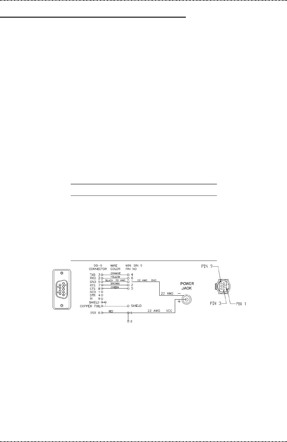
PIN Pad 791 Programmer’s Manual (PCI POS-A) UDN PM0103-U Rev. 06
Appendix C – Features and specification 2015-04-20
Page329
Uniform Industrial Corp. Proprietary and Confidential Total 342 pages
Appendix C Features and specification
Micro controller: i.MX258 micro processor (running at 400MHz).
Memory: 64MB DDR2 RAM, 4GB Flash
Display: 320*240 pixels LCD display.
Key Pad: 16 keys keypad, the digit keys are randomly scanned.
PIN encryption: 1. Follows ANSI X9.8 for PIN block and National Bureau of Standard DES / Triple
DES algorithm in Electronic Code Book mode.
2. EMV level 2 specified PIN block with RSA encryption (maximum 1984bits mod)
Key management : 1. Master/ Session key (MK/SK).
2. Unique Key Per Transaction conforms to ANSI X9.24-1992 and 2002.
(MK/SK and DUKPT is mutual exclusive, different message format needed.)
3. RSA public key injection with DES/TDES authentication.
Message Frame: Compatible to VISA specifications.
Interface: [USB] mini-DIN 9-pin Connector (to Standard A-Type plug.)
[RS232] mini-DIN 9-pin Connector (to DB9 RS232 connector.)
Preset to: 9600 BPS, 8 bits per character, none parity, one stop bit.
Pin assignment DB9 mini-DIN
TXD, from PIN pad 3 4
RXD, to PIN pad 2 6
GND 5 1
RTS 7 2
CTS 8 5
+5VDC(needs Ext. DC adapter) N/A 9 and 8
Power: Regulated +5VDC input, 400mA (typical); 500mA (max.).
Battery Life: 4 years for Security Data backup.
Diagnostic: Self-diagnostic includes MCU, Program checksum and Key checksum test.
Dimension: 169mm (L) x 85mm (W) x 43mm (H)
MSR Option: ISO7811, 3 tracks.
Smart card reader: ISO7816-1, 2, 3 and EMV 4.3 Level 1 & Level 2 certified.
Reads T=0, T=1 cards. Have one primary and three SAM card interface.

PIN Pad 791 Programmer’s Manual (PCI POS-A) UDN PM0103-U Rev. 06
Appendix D – Tag Definition on EMV data 2015-04-20
Page330
Uniform Industrial Corp. Proprietary and Confidential Total 342 pages
Appendix D Tag Definition on EMV data
There are some data needed in EMV transaction but not given tag definition by EMV. Here PP791
defines tags on the following data that will used in EMV transaction.
Terminal Configuration Data:
Name Description Format Tag Length
Terminal UI
Capability
0:Make PIN pad selects the highest
priority application and ask user’s
confirmation.
1:Make PIN pad ask the confirmation
from user for EMV application with
highest priority in candidate list.
2:Make PIN pad provides a list of
candidate applications.
b 50000002 1
MSR
Processing
Batch Tag
List
PIN pad will store transaction data
according to the tag list while the
transaction is performed as MSR
processing. Ex, for tag list (829F365F3
09F399F029F03), PIN pad will store
transaction data of tag number 0x82,
0x9F36, 0x5F30, 0x9F39, 0x9F02 and
0x9F03.
b 50000003 var
Online PIN
Block Tag
Define
User can define new tag number for
online PIN block.
b 50000004 1~4
Online PIN
Key Tag
Define
User can define new tag number for
online PIN key.
b 50000005 1~4
EMV Application Configuration Data:
Name Description Format Tag Length
Application Selection Indicator 0: Full AID matching.
1: Partial AID matching
n 40000001 1
Threshold Value for Biased
Random Selection
Format is same as
“Amount Authorized
(Numeric)” defined by
EMV. It must be zero
n 40000004 6

PIN Pad 791 Programmer’s Manual (PCI POS-A) UDN PM0103-U Rev. 06
Appendix D – Tag Definition on EMV data 2015-04-20
Page331
Uniform Industrial Corp. Proprietary and Confidential Total 342 pages
or a positive number
less than the floor limit
(Refer to EMV.).
Target Percentage to be used
for Biased Random Selection
0x00 ~ 0x63 b 40000005 1
Maximum Target Percentage to
be used for Biased Random
Selection
0x00 ~ 0x63 b 40000006 1
Terminal Action Code - Default Refer to EMV 4.3
BOOK 3, section 10.7
b 40000007 5
Terminal Action Code - Denial Refer to EMV 4.3
BOOK 3, section 10.7
b 40000008 5
Terminal Action Code - Online Refer to EMV 4.3
BOOK 3, section 10.7
b 40000009 5
Data tags required in Online
message (ARQC)
See below b 4000000A var.
Data tags required in reversal
message
See below b 4000000D var.
Data tags for batch data capture See below b 40000010 var.
ARC Approve See below b 4000001A var.
ARC Decline See below b 4000001B var.
ARC Referral See below b 4000001C var.
Note. The contents in data object with tag value 0x4000000A ~ 0x40000010 are a list of tags with
asterisks as separators. Ex. The contents 95*9F02*82* in data object with tag value
(0x4000000A) means that there are three data objects, Terminal Verification Results (0x95),
Amount Authorized (0x9F02) and Application Interchange Profile (0x82) will be necessary for
online transaction.
Note. The data objects with tag value 0x4000000A ~ 0x40000010 are used for customer-defined
application on PIN pad. If customer installed these information into PIN pad previously,
customer-defined application could apply APIs provided by PIN pad to implement an EMV
transaction and without modification on application if the data required for online message is
changed.
Note. ARC Approve / Decline / Referral is used for customer to define their definition of ARC code.
Customer can concatenate a list of ARC value for definition of Approve, Decline or Referral.
Ex. If ARC Approve is 0x303031313536, PIN pad will treat ARC with value 0x3030, 0x3131
and 0x3536 as that Host approves this transaction online.
Transaction Result Data:
Name Description Format Tag Length

PIN Pad 791 Programmer’s Manual (PCI POS-A) UDN PM0103-U Rev. 06
Appendix D – Tag Definition on EMV data 2015-04-20
Page332
Uniform Industrial Corp. Proprietary and Confidential Total 342 pages
Issuer Script
Result
The result of terminal script processing. b 9F5B var
Enciphered
PIN block
Transaction PIN enciphered at the PIN
pad for online verification.
b 9F72 8
These data object are defined in EMV 4.3 BOOK3, Annex A without tag values. The tag values are
defined by PIN pad.

PIN Pad 791 Programmer’s Manual (PCI POS-A) UDN PM0103-U Rev. 06
Appendix E – Minimun Set of EMV Configuration Data 2015-04-20
Page333
Uniform Industrial Corp. Proprietary and Confidential Total 342 pages
Appendix E Minimum Set of EMV Configuration Data
For a complete transaction, user has to load minimum set of terminal configuration data and EMV
application data into PIN pad.
Minimum set of Terminal configuration Data.
Mandatory:
Merchant Category (9F15), Merchant ID (9F16), Terminal Country Code (9F1A), Terminal ID (9F1C),
IFD Serial NO. (9F1E), Terminal Capabilities (9F33), Terminal Type (9F35), Additional Terminal
Capabilities (9F40), User Application Confirmation (50000002), MSR Batch data tag list (50000003),
Online PIN block tag define (50000004), Online PIN key tag define (50000005)
Optional:
Merchant Name and Location (9F4E), Terminal Risk Management Data (9F1D)
Note. User Application Confirmation is used to enable / disable PIN pad to build a AID list for
cardholder to select EMV application.
Minimum set of EMV application configuration Data.
Application Selection Indicator (40000001), Threshold Value for Biased Random Selection (40000004),
Target Percentage for Random Selection (40000005), Maximum Target Percentage
for Biased Random Selection (40000006), ARQC Tag list (4000000A), Reversal Tag
list (4000000D), Batch Tag list (40000010), Default TDOL (97), Acquirer Identifier
(9F01), Application Identifier (9F06), Application Version Number (9F09), Default
Dynamic Data Authentication Data Object List (9F49), Terminal Floor Limit (9F1B),
Optional:
Terminal Action Code (Default) (40000007), Terminal Action Code (Denial) (40000008), Terminal Action
Code (Online) (40000009)

PIN Pad 791 Programmer’s Manual (PCI POS-A) UDN PM0103-U Rev. 06
Appendix F – PCD Tag Definition on EMV data 2015-04-20
Page334
Uniform Industrial Corp. Proprietary and Confidential Total 342 pages
Appendix F PCD Tag Definition on EMV data
There are some data needed when do the EMV transaction but do not given tag definition by EMV
Contactless specifications v2.4. PIN pad defines its unique tags on the following data.
Table C-1 describes the self-define tag for PCD EMV Level2
Table C-2 describes the self-define tag for qVSDC and payWave.
Table C-3 describes the self-define tag for PayPass.
Table C-4 describes the self-define tag for expresspay.
EMV Application Configuration Data:
Table C-1: The self-define tag for PCD EMV Level2
Name Description Format Tag Length
Application Selection
Identifier
0: Full AID matching.
1: Partial AID matching
n 40000001 1
Kernel ID 020000: PayPass
030000: qVSDC and payWave
040000: expresspay
b 40000020 3
Status Check 0 : Disable Status Check.
1 : Enable Status Check.
Please refer to EMV Contactless Specifications
v2.4 BOOK B, section 3.1
b 40000022 1
Zero Amount Allowed 0: not allowed(option 2)
1: allowed(option 1)
2: disable
Please refer to EMV Contactless Specifications
v2.4 BOOK B, section 3.1
b 40000023 1
Contactless Floor Limit Please refer to EMV Contactless Specifications
v2.4 BOOK B, section 3.1
n 40000024 6
Contactless
Transaction Limit
Please refer to EMV Contactless Specifications
v2.4 BOOK B, section 3.1
n 40000025 6
CVM Required Limit Please refer to EMV Contactless Specifications
v2.4 BOOK B, section 3.1
n 40000026 6
Table C-2: The self-define tag for qVSDC and payWave
Name Description Format Tag Length
CVN 17 switch 0 : Disable CVN 17 b 40000030 1

PIN Pad 791 Programmer’s Manual (PCI POS-A) UDN PM0103-U Rev. 06
Appendix F – PCD Tag Definition on EMV data 2015-04-20
Page335
Uniform Industrial Corp. Proprietary and Confidential Total 342 pages
1 : Enable CVN 17
PIN pad Configuration
Parameters
This tag used to set up qVSDC and payWave
configuration.
Byte 1
bit 8-3: RFU
bit 2: Exception file check
enabled(1b)/disabled(0b)
bit 1: RFU
Byte 2: RFU
b 40000033 2
Track 1&2 configure Bit 3: 0: Disable Track 2, 1: Enable Track 2
Bit 2: 0: Disable Track 1, 1: Enable Track 1
Bit 1: 0: Output Tag 57, 1: format track 2
b 40000035 1
Table C-3: The self-define tag for PayPass
Name Description Format Tag Length
None None None None None
Table C-4: The self-define tag for expresspay
Name Description Format Tag Length
Terminal Action Code -
Default
Please refer to EP3.0 section 12, [EMV4.2 iii]
section 10.7 and [EMV4.2 iv] section 6.3.6.
b DF808003 5
Terminal Action Code -
Denial
Please refer to EP3.0 section 12, [EMV4.2 iii]
section 10.7 and [EMV4.2 iv] section 6.3.6.
b DF808004 5
Terminal Action Code -
Online
Please refer to EP3.0 section 12, [EMV4.2 iii]
section 10.7 and [EMV4.2 iv] section 6.3.6.
b DF808005 5
PIN pad Configuration
Parameters
This tag used to set up AE configuration.
Byte 1
bit 8: Status Check enabled(1b)/disabled(0b).
bit7: Amount Authorized of Zero Check
enabled(1b)/disabled(0b)
bit 6: Amount Authorized of Zero Option option
1(1b)/Option 2(0b), this bit is applicable
when the PIN pad is online capable.
bit 5: PIN pad Contactless Transaction Limit
Check enabled(1b)/disabled(0b)
bit 4: PIN pad CVM Required Limit Check
enabled(1b)/disabled(0b)
bit 3: PIN pad Contactless Floor Limit Check
enabled(1b)/disabled(0b)
b DF808006 2

PIN Pad 791 Programmer’s Manual (PCI POS-A) UDN PM0103-U Rev. 06
Appendix F – PCD Tag Definition on EMV data 2015-04-20
Page336
Uniform Industrial Corp. Proprietary and Confidential Total 342 pages
bit 2: Exception file check
enabled(1b)/disabled(0b)
bit 1: Revocation list check
enabled(1b)/disabled(0b)
Byte 2: RFU
Magstripe
Unpredictable Number
Range
PIN pad use the random number of month (RNM)
for the unpredictable number with ‘0000YYMM’
format. The formula is
RNM: = UNEMV mod (UNR + 1)
n DF808008 2
Track 1&2 configure Bit 3: 0: Disable Track 2, 1: Enable Track 2
Bit 2: 0: Disable Track 1, 1: Enable Track 1
Bit 1: 0: Output Tag 57, 1: format track 2
b DF808071 1

PIN Pad 791 Programmer’s Manual (PCI POS-A) UDN PM0103-U Rev. 06
Appendix G – Minimum Set of EMV Configuration Data 2015-04-20
Page337
Uniform Industrial Corp. Proprietary and Confidential Total 342 pages
Appendix G PCD Minimum Set of EMV Configuration Data
To do an EMV transaction, user has to setup minimum set of terminal configuration data and EMV
application data into PIN pad.
Minimum set of Terminal configuration Data.
Mandatory:
Terminal Country Code (9F1A).
Optional:
Merchant Category (9F15), Merchant ID (9F16), Merchant Name and Location (9F4E),
Terminal ID (9F1C), IFD Serial NO. (9F1E), Terminal type (9F35).
Minimum set of EMV application configuration Data.
PCD EMV Level2:
Application Identifier(9F06),
Transaction Type(9C)
Application Selection Identifier(40000001),
Kernel ID(40000020),
Contactless Floor Limit(40000024),
Contactless Transaction Limit (40000025),
CVM Required Limit (40000026)
For qVSDC and payWave:
Terminal Transaction Qualifiers(9F66),
POS Entry Mode(9F39),
Terminal Floor Limit (9F1B),
Terminal Verification Result(95),
qVSDC and payWave CVN 17 switch(40000030),
PIN pad Configuration Parameters(40000033),
Track 1&2 configure(40000035).
Terminal Entry Capability(DF8170),
For PayPass:
None.
For expresspay:
expresspay Terminal Capabilities(9F6D),
Terminal Transaction Capabilities(9F6E),

PIN Pad 791 Programmer’s Manual (PCI POS-A) UDN PM0103-U Rev. 06
Appendix G – Minimum Set of EMV Configuration Data 2015-04-20
Page338
Uniform Industrial Corp. Proprietary and Confidential Total 342 pages
Application Version Number(9F09),
Terminal Floor Limit(9F1B),
Terminal Capabilities (9F33),
Terminal Type(9F35)
Terminal Action Code – Default(DF808003),
Terminal Action Code – Denial(DF808004),
Terminal Action Code – Online(DF808005),
PIN pad Configuration Parameters(DF808006),
expresspay Magstripe Unpredictable Number Range(DF808008),
Set Track 1&2 configure(DF808071).

PIN Pad 791 Programmer’s Manual (PCI POS-A) UDN PM0103-U Rev. 06
Appendix H – Fixed Prompts for Z2/Z3 Authenticated Mode 2015-04-20
Page339
Uniform Industrial Corp. Proprietary and Confidential Total 342 pages
Appendix H Fixed Prompts for Z2/Z3 authenticated mode
Prompt ID Display
001 ENTER VALUE
002 ENTER PHONE
003 ENTER CUST ID
004 ENTER AMOUNT
005 PLEASE ENTER
006 ENTER CARD ID
007 ENTER POINTS
008 ENTER ACCOUNT
009 ENTER LOYALTY
010 ENTER ZIP CODE
011 ENTER VEHICLE
012 ENTER EMPLOYEE
013 ENTER ID NUMBER
014 ENTER DRIVER ID
015 ENTER CASH BACK
016 DRIVER LICENSE
017 PLEASE RE-ENTER
018 REENTER DRIVER ID
019 ENTER DRIVER LICENSE
020 ENTER BIRTH DATE
021 REENTER ZIP CODE
022 ENTER MEMBERSHIP
100 ACCOUNT NUMBER
101 AIRCRAFT TAIL NO
102 BADGE NUMBER
103 CARD NUMBER
104 CARD SEC CODE
105 CASH BACK AMOUNT
106 CID CODE
107 CVC CODE
108 CVN CODE
109 CVV CODE
110 CUSTOMER CODE
111 CUSTOMER DATA
Prompt ID Display
112 CUSTOMER ID
113 CUSTOMER NUMBER
114 CUSTOMER REF
115 CUSTOMER REF NO.
116 DATE OF BIRTH
117 DEPARTMENT NO.
118 DRIVER ID
119 DRIVER LICENSE
120 DRIVER NUMBER
121 EMPLOYEE ID
122 EMPLOYEE NUMBER
123 ENTER
124 ENTER ACCOUNT #
125 ENTER AIR TAIL #
126 ENTER BADGE #
127 ENTER BIRTH DATE
128 ENTER CARD #
129 ENTER CASH BACK
130 ENTER CUST #
131 ENTER CUST CODE
132 ENTER CUST DATA
133 ENTER CUST ID
134 ENTER CUST REF
135 ENTER CUST REF #
136 ENTER CID CODE
137 ENTER CVC CODE
138 ENTER CVN CODE
139 ENTER CVV CODE
140 ENTER DEPT #
141 ENTER DOB
142 ENTER DRIVER #
143 ENTER DRIVER ID
144 ENTER DRIVER LIC
145 ENTER EMP ID

PIN Pad 791 Programmer’s Manual (PCI POS-A) UDN PM0103-U Rev. 06
Appendix H – Fixed Prompts for Z2/Z3 Authenticated Mode 2015-04-20
Page340
Uniform Industrial Corp. Proprietary and Confidential Total 342 pages
Prompt ID Display
146 ENTER EMPLOYEE #
147 ENTER EXP DATE
148 ENTER FLEET #
149 ENTER FLEET DATA
150 ENTER HOME PHONE
151 ENTER ID #
152 ENTER JOB #
153 ENTER ODOMETER
154 ENTER PHONE #
155 ENTER PO #
156 ENTER REF #
157 ENTER ROUTE #
158 ENTER SEC CODE
159 ENTER SERIAL #
160 ENTER SOC SEC #
161 ENTER SSN
162 ENTER STREET #
163 ENTER TRAILER #
164 ENTER USER ID
165 ENTER V-CODE
166 ENTER VEH CARD #
167 ENTER VEHICLE #
168 ENTER VEHICLE ID
169 ENTER WORK PHONE
170 ENTER ZIP CODE
171 EXPIRATION DATE
172 FLEET DATA
173 FLEET NUMBER
174 HOME PHONE NO.
175 ID NUMBER
176 JOB NUMBER
177 MMDDYY
178 MMDDYYYY
179 MMYY
180 ODOMETER READING
181 OR PHONE #
182 OR PHONE NUMBER
Prompt ID Display
183 PHONE NUMBER
184 PLEASE
185 PLEASE ENTER
186 PLEASE RE-ENTER
187 PO NUMBER
188 RE-ENTER
189 REFERENCE NUMBER
190 RESTRICTION CODE
191 ROUTE NUMBER
192 SECURITY CODE
193 SERIAL NUMBER
194 SOCIAL SEC NO.
195 STREET NUMBER
196 SWIPE CARD
197 SWIPE CARD OR
198 TRAILER NUMBER
199 USER ID
200 V-CODE
201 VEHICLE CARD NO.
202 VEHICLE ID
203 VEHICLE NUMBER
204 WORK PHONE NO.
205 ZIP CODE

PIN Pad 791 Programmer’s Manual (PCI POS-A) UDN PM0103-U Rev. 06
Appendix I – Fixed Prompts for Z2/Z3 PIN entry mode 2015-04-20
Page341
Uniform Industrial Corp. Proprietary and Confidential Total 342 pages
Appendix I Fixed Prompts for Z2/Z3 PIN entry mode
Prompt ID Display
001 ENTER PIN
002 ENTER YOUR PIN
003 PLEASE ENTER PIN
004 THEN PUSH ENTER
005 THANK YOU